
Abstract
Traction drive is a useful power transmission method for reducing noise of high-rotational-speed motors of electric vehicles. To realize a highly efficient traction drive system, normal force between rollers must be optimized. This study uses a piezoelectric actuator to adjust the normal force. A piezoelectric actuator, which deforms according to the applied voltage, can output large force. Nevertheless, piezoelectric actuator cannot be integrated with a force sensor that has low stiffness. Therefore, we have developed a normal force control method that observes the slip between rollers rather than the normal force. A two-roller test bench has been developed to confirm its efficiency. Experimentally obtained results demonstrate that the proposed system can achieve considerably high efficiency.
Introduction
Urgent necessity for environmental measures demands the increased use of electric vehicles (EVs), which have low CO2 emissions, discharging few air pollutants during operation.1,2 This movement encourages more rapid motor revolutions to enhance the power of an EV motor without enlarging the motor size. A high-speed motor with a conventional gear system generates much noise because of teeth contact. Although studies of gear noise reduction are in progress,3,4 the mechanical configuration of a gear system in which a contact period and a non-contact period are repeated intermittently does not permit perfect noise reduction.
Accordingly, the traction drive, a speed reducer with no teeth, has been attracting attention. A traction drive is a power transmission system using the shear force of oil (Figure 1). Because it requires a pair of rollers to be pushed strongly with respect to one another, its efficiency is lower than that of a gear reducer because of the great mechanical loss in bearings. Particularly excessive normal pressing force increases the mechanical loss and degrades efficiency, although insufficient pressing force causes a huge slip that interrupts power transmission.

Traction drive principle.
Moreover, the appropriate amount of pressing force varies with the operational state, such as output torque and oil temperature. It is therefore necessary to adjust the normal pressing force according to service conditions to improve efficiency at each operational state. Especially, the wide range of fluctuation of torque and oil temperature in an EV demands the optimization of normal force.
The methods of adjusting normal force include mechanical types using a loading cam that generates normal force according to torque, 5 a spring and a ball screw, 6 and the wedge effect. 7 These systems have low efficiency because of the excessive normal force at low oil temperatures because their design is optimized for high oil temperature conditions. 8
Actuator-type adjusting methods include a system using hydraulic pressure, 9 but their efficiency is still low in principle because of losses caused by oil viscosity. Moreover, actuators using electric motors, such as a motor cylinder, must be used in the state of low efficiency where an electric motor rotates at extremely few revolutions per minute, so that loss by heat generation of a coil is unavoidable.
The authors propose a pull-out system that adjusts the normal force in a highly efficient and extremely reliable manner using piezoelectric devices with excellent electromechanical conversion efficiency (Figure 2).

Schematic diagram of pull-out system.
This method applies pre-pressure between rollers and decreases and adjusts the normal force with a piezoelectric element. However, because of the force–displacement relation of a piezoelectric device, the infinitesimal displacement of a piezoelectric device is used only to deform a force sensor of low stiffness, so that the adjustment performance of normal force is degraded. In addition, because insufficient normal force in a traction drive is fatal, it is necessary to avoid the unstable state of a huge slip that ends up with power transmission failure. Consequently, this article addresses the feasibility study of stable and highly efficient control of a pull-out system, in which normal pressing force is not measured but controlled using other controlled variables.
Normal force control using slip ratio as controlled variable
Physical quantities to define operational state of traction drive
The operational state of a traction drive is expressed by the following six variables: input revolution, output revolution, input torque, output torque, normal force, and oil temperature. This study assumes that input revolution, output torque, and oil temperature are given as requirements or constraints. Then, normal force determines an output revolution and (necessary) input torque.
Slip ratio and loss in traction drive
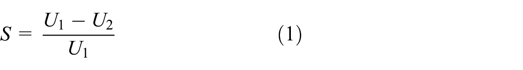
Slip ratio variable S is defined as shown in equation (1). It serves as an index of the slip state of a traction drive, where
Muraki
10
investigated the relation between the normal force and slip ratio of a traction drive, by computing traction coefficient

Therein


The Hertzian contact equations are used for computation of the contact pressure, which teach that the mean pressure on a contact surface

Next, the relation between efficiency and slip ratio is discussed. First, the loss of a traction drive is roughly classifiable into three categories: (1) “mechanical loss” by friction of bearing and deformation of components, (2) “slip loss” by shearing of oil caused by slip between rollers, and (3) “fluid loss” by stirring and trapping of oil.
Among these, mechanical loss is represented by the bearing loss. Because the bearing loss results from the friction loss of a bearing, it is mostly linearly related to revolutions and normal force. Slip loss takes place when an oil film is sheared at a contact part. Because it is expressed by the product of traction force and slip velocity, slip loss is linearly related to the slip ratio. Fluid loss, represented by the stirring loss, is fundamentally the loss by shearing of oil at anywhere other than a contact part. Oil is approximated as a Newtonian fluid. Shear force, a product of viscosity and sliding velocity, is regarded as almost constant in the case of a slight difference in rotational speed, fixed oil temperature, and slight variation in viscosity.
As described above, the slip ratio and loss are presumed to behave as in Figure 3, which suggests that the loss has a minimum to the slip ratio, that is, efficiency has a maximum to the slip ratio. Highly efficient normal force control of a traction drive is expected to be attained by setting a slip ratio when taking this maximal value as a target value.
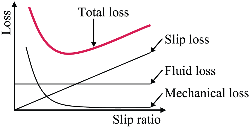
Loss–slip ratio graph of traction drive.
Consequently, it is considered feasible to adjust the normal force of a traction drive using the slip ratio as a controlled variable. Laboratory equipment is designed and manufactured. This study elucidated that normal force control using the slip ratio as a controlled variable is effective for efficiency improvement.
Development of two-roller testing machine
A two-roller testing machine, the simplest testing apparatus used as a traction drive tester, was designed and manufactured as portrayed in Figure 4.
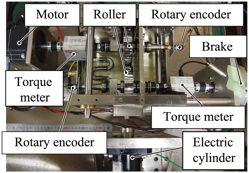
Photograph of two-roller machine.
This testing machine can measure an operational state with input revolution, output torque, and make oil temperature fixed. The input roller is rotated by a brushless motor (BXS6400C-A-2; Oriental Motor Co. Ltd). Power is transmitted to the output roller pushed against the input roller by the traction drive phenomenon. The transmitted power is consumed by hysteresis brakes (HB-250M-2; Magtrol Inc.). Because the parallelism of the rollers is sustained in the two-roller testing machine, no loss arises by slip other than along the power transmission direction.
A normal force adjustment method can be selected from the following two modes: a pull-out system using piezoelectric actuators (ASB340C801FP0LF; NEC Tokin Corp.) (mode P) and a press-on system using an electric cylinder (PC30-MR; THK Co. Ltd) (mode C). Normal pressing force cannot be measured in mode P because of restrictions of the maximum displacement of a piezoelectric actuator, although it is measurable in mode C by a load cell (LMB-A-2kN; Kyowa Electronic Instruments Co. Ltd). Four piezoelectric devices with maximum displacement of 34 µm and a maximum generative force of 800 N are installed in parallel. All four piezoelectric devices are controlled by one amplifier. It means that the same voltage is applied to those four devices. The rated generative force of the electric cylinder is 1.6 kN.
A torque meter (UTM-II; Unipulse Co.) of a rated measurement range of 2 N m is used for torque measurement. Revolution is measured using a rotary encoder (MES20-5400P; Microtech Laboratory Inc.), which divides one turn into 5400 pulses. Forced lubrication by pumping is adopted because it is difficult to prevent from oil temperature fluctuation and contamination in splash lubrication. The oil flow rate is 80 mL/min. A filter is installed in the flow path to eliminate foreign objects that are 3 µm or larger, to prevent foreign objects from being caught at a contact part. Oil temperature is set constant using a temperature controller (MTCRM; Misumi Corp.). TDF32 by Idemitsu Kosan Co. Ltd was adopted as a traction oil of which the physical properties at 40°C are the following: 0.943 g/cm3 density, 32.4 mm2/s kinematic viscosity, a pressure–viscosity coefficient that indicates the degree of pressure dependence of viscosity is 29 GPa−1, and heat conductivity of 0.120 W/(m K).
Next, the roller design is described. Because roller surfaces are exposed to high pressure of GPa order, both input and output rollers are made of JIS SUJ2 bearing steel. They have a 100-mm diameter and 20-mm length. The output roller has a curvature of R200 on the contact surface. Experimentation on point contact conditions can enhance the pressure at the point of contact and allows an experiment at a high driving torque. The roller surfaces are subjected to induction hardening and buffing. These processes allow the rollers to endure the highly stressed condition and make it possible to pursue the energy optimality. They have mean square roughness Rq of about 0.05–0.18. These preparations support experiments with no effect of surface roughness on a traction coefficient.
LabVIEW by National Instruments Corp. (USA) is used for the measurement control system. The measurement frequency is 200 Hz: much greater than a rotating period. Figure 5 schematically depicts the measurement and control system of the two-roller testing machine.

Measurement and control system of two-roller machine.
Experiment 1: examination experiment of relation between efficiency and slip ratio
The purpose of this experiment is to elucidate the relation of normal pressing force, slip ratio, and efficiency. Pressing force adjustment in this experiment was conducted in mode C using an electric cylinder that can measure normal force. Input revolution, output torque, and oil temperature were set as the conditions in Table 1.
Configurations of experiment 1.

Then normal force was decreased gradually at an interval of 5 s from an excessive pressing state. The input–output revolution, input–output torque, normal force, and oil temperature were measured. Measurement was terminated when a huge slip occurred by a decrease in the normal pressing force and measurement at a stationary state became impossible. Evaluation was conducted for the average of 3–5 s after normal force being changed in this experiment, to evaluate the relation at a stationary state. Figure 6 presents charts of (1) time series data, (2) normal force to torque loss at no-load, (3) a normal force–slip ratio, and (4) an efficiency–slip ratio.

(a) Acquired time series data, (b) normal force to torque loss graph, (c) efficiency–slip ratio graph, and (d) normal force–slip ratio graph.
Experimental values and theoretical calculation values were compared in this experiment with respect to the relation between the efficiency and slip ratio. The computation procedure of theoretical calculation values is described. First, linear approximation of torque loss at no load was conducted using the least-squares method. Table 2 presents a slope and intercept for each condition.
Parameters for linear approximation of torque loss.

Torque loss can be estimated by the sum of mechanical loss and fluid loss at no-load because the slip loss is negligibly small. Because the mechanical loss is linearly related to the normal force and revolution, the part linearly increasing to the normal force in Figure 6(b) is regarded as the mechanical loss. In contrast, torque loss independent of the normal force is regarded as fluid loss. It is presumed as almost constant at fixed revolution and isoviscous at constant temperature because it is generated by the shear of oil at locations other than the contact part. Because the slip ratio is presumed to be 0.02 or less in this experiment, the difference in each loss by the change of output revolution is regarded as negligible. Consequently, the mechanical loss and fluid loss can be computed given the relation between the normal force and slip ratio, even for cases of the same input revolution and oil temperature but different torque from these results.
The computation procedure of each loss at this time is the following. We designate the input angular velocity as
Mechanical loss


Each experimentally obtained result is discussed herein. The chart of normal force–slip ratio in Figure 6(c) shows that normal force decreases monotonously to the slip ratio. The absolute value of the slope decreases as the slip ratio increases because the slip ratio increases as the normal force declines, the temperature of the oil film between rollers rises in connection, and viscosity drops. As described above, the slip ratio changes drastically in response to an infinitesimal change of normal force under the effect of temperature rise of the oil film at a great slip ratio range. It is therefore difficult to control.
The chart of the efficiency–slip ratio in Figure 6(d) shows close agreement between calculated values and experimental values, so that data acquired in this experiment are regarded as reasonable even theoretically. Efficiency takes a maximum to slip ratio in the experimental range on condition of an output torque as great as 800 mN m, although no peak was observed at torques as small as 120 and 380 mN m within the experimental range. A maximum might exist at a slip ratio greater than the experimental range.
Figure 7 presents details of the calculated loss at 800 mN m, which suggests that the decrement of mechanical loss and the increment of slip loss because of increase in slip ratio are in equilibrium to take a minimum at a slip ratio of about 0.005 in the case of 800 mN m. It is considered that no minimum appeared within the experimental range of a slip ratio of 0.00–0.02 at a small output torque range (120 mN m) in Figure 6(d) because the increment of the slip loss to the slip ratio was too small.
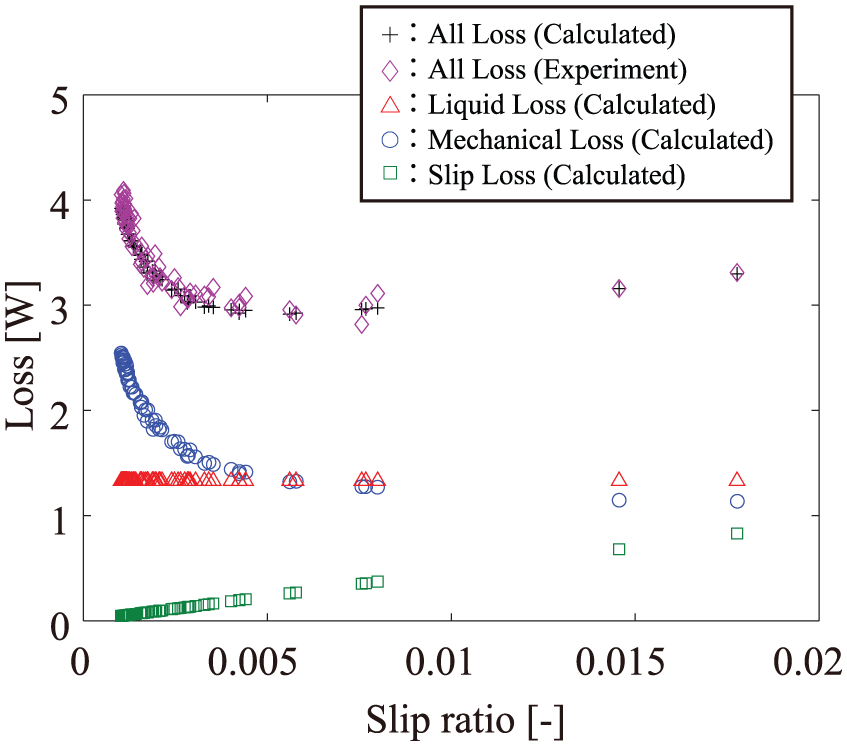
Calculated and experimental loss values (600 r/min, 800 mN m, 40°C).
Results show that efficiency takes a maximum to the slip ratio. It is effective as a controlled variable in a high output torque range.
Experiment 2: evaluation experiment of efficiency improvement by normal force control
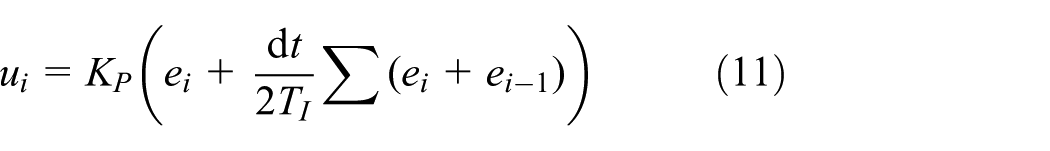
The objective of this experiment is to verify high-efficiency control by setting a target value using the slip ratio as a controlled variable in the pull-out system (mode P) using piezoelectric devices. Output torque is varied stepwise from 80 to 380 then 120 mN m at an interval of 8 s at an input revolution of 846 r/min and an oil temperature of 40°C. Efficiency is compared in the following two cases in that event to demonstrate the efficiency improvement by control with the slip ratio fixed: (1) proportional–integral (PI) control to maintain a constant slip ratio at the pull-out system using piezoelectric devices and (2) pressing at constant pressure (fixed applied voltage of the piezoelectric device). In case (1), the equation of PI control is shown in equation (11), where
The control frequency (the reciprocal of dt) was 25 Hz. As described previously, the measurement period was 200 Hz. In the control process, the average of multiple samples was used. This eliminates the effect of unintended external disturbance.
Figure 8(a) presents time series data of the slip ratio and efficiency at pressing at constant pressure; Figure 8(b) shows those with a target slip ratio of 0.006 and a P gain of 750. The slip ratio converged to the target value at a constant slip ratio control. Thereby normal force control with the slip ratio as a controlled variable was realized. The target value of the slip ratio 0.006 was made into a representative value in this experiment.

Time series data of slip ratio and efficiency of two control conditions: (a) pressure (voltage) is constant and (b) slip ratio is controlled.
An impression command voltage of the piezoelectric device of 9 V at pressing at constant pressure produced a huge slip and torque transmission failure once every three times. Accordingly, data for an impression command voltage of 7.5 V were used as the representative value of pressing at constant pressure. It is noteworthy that a larger impression command voltage signifies a smaller normal force in the pull-out system.
Figure 9 shows efficiency at a stable control state of torque at each condition. This figure suggests that control using the slip ratio as a controlled variable is highly efficient, especially at a low torque of 80 mN m, because pressing at constant pressure yields an excessive pressing state at low torque, although it does not take place in the control using slip ratio as a controlled variable. Consequently, the control using slip ratio as a controlled variable prevents excessive pressing and supports highly efficient control.
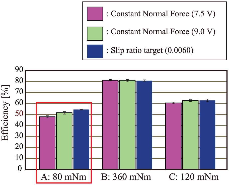
Efficiency of control conditions.
Conclusion
Traction drive propulsion is attracting attention as a candidate to solve noise problems accompanying higher-rate revolutions of EV motors. However, traction drives have the shortcoming of low efficiency compared with conventional gear reducers. To realize high efficiency in a traction drive, the authors have proposed a novel normal force adjustment method with great electromechanical conversion efficiency: a pull-out system using piezoelectric devices.
This method applies pre-pressure between rollers and decreases and adjusts normal pressing force with piezoelectric elements in a fail-safe manner. However, in this method, the adjustment performance of normal force is degraded when it is measured using a force sensor with large displacement. Therefore, a procedure was devised for controlling normal force with high efficiency using a slip ratio as a controlled variable without measuring the normal force.
The relation of efficiency, slip ratio, and normal force in a traction drive is revealed in this study through experiments using a two-roller testing machine. The obtained findings are summarized as the following two points:
Efficiency is convex to the slip ratio, which takes a maximum at a point where the slip loss increment and mechanical loss decrement are in equilibrium.
Normal force decreases monotonously to the slip ratio. The absolute value of the slope decreases as the slip ratio increases.
Moreover, this study has demonstrated experimentally that normal force can be controlled using the slip ratio as a controlled variable without direct measurement of the normal force at the pull-out system. Results also show that efficiency improves especially at low torque compared with pressing at constant pressure. Our future task is to develop a method of setting the target value of the slip ratio according to service and vehicle conditions.
Footnotes
Handling Editor: Xiao-Jun Yang
Declaration of conflicting interests
The author(s) declared no potential conflicts of interest with respect to the research, authorship, and/or publication of this article.
Funding
The author(s) received no financial support for the research, authorship, and/or publication of this article.