
Abstract
The problem of overlarge current protection of permanent magnet synchronous motor based on a single-loop control structure is discussed in this article. Under this structure, the previous limiting method of amplitude of q-axis current used in field-oriented control is unsuitable, which limits q-axis current by restricting the output of reference current. Conventional controllers (e.g. proportional–integral–derivative controller) usually cannot have a nice balance between satisfaction of current constraint and requirement of fast dynamic performance. Overlarge current may cause the damage of hardware. Aiming at this issue, a composite controller is proposed. Different from previous methods of state constraints, the effects of disturbance is taken into account of controller design. First, a finite-time current-constrained feedback control technique based on homogeneous approach is applied in the feedback design. Compared with conventional finite-time control, a punishment mechanism of over-current is added into the gain of controller. Second, a generalized proportional integral observer is adopted to estimate the uncertainties and disturbances. The estimated value is used in the feed-forward compensation design. Compared with the conventional proportional–integral–derivative controller and proportional–derivative + extended state observer controller, the proposed method not only limits q-axis current to a safe range but also shows a nice dynamic performance and a strong anti-disturbance ability. Both simulations and experiments are carried out, and the results demonstrate the effectiveness of the proposed control scheme.
Keywords
Introduction
Attributing to the advantages of simple structure, small size, light weight, high power, efficiency, torque-to-inertia, and so on, permanent magnet synchronous motor (PMSM) is widely applied in aeronautics and astronautics, numerical control machines, robots, electric automobiles, and other industrial fields.1–5
So far, a cascade structure is widely used in PMSM control systems under the well-known field-oriented control (FOC) framework. For the inner and outer-loop, proportional plus integral (PI) controllers are widely employed. In the early time, the design of the control period of the speed loop is greater than the current loop (usually 5–10 times) in PMSM control systems. However, in more recent years, this kind of difference is becoming smaller and even disappearing. For example, in Baumüller servo product (b maXX 4000), position control, speed control, and current control are integrated together, and all have a cycle time of 125 µs. 6 Hence, in such cases, a single-loop structure can be seen as an alternative scheme which merges speed loop and current loop into one loop. However, in practical application, the single-loop structure still faces with the critical problem of how to design overlarge current protection in practical application. It is different from the cascade control, which could limit q-axis current by restricting the reference current output. As the speed loop and the current loop are merged into one loop, the q-axis current becomes a state of PMSM control system instead of the output of current loop in the cascade control. While the conventional proportional–integral–derivative (PID) controller of PMSM under the single-loop structure usually balances current constraint requirement and dynamic performance, an overlarge transient current may cause the damage of hardware circuit and the loss of property. A common idea to solve this problem is to select relatively conservative control parameters, but the dynamic performance of control system is sacrificed to some extent.
Thus, under the single-loop structure, the design of controller of PMSM in the presence of state constraints is a challenging problem from both theoretical and practical aspects. In the study of Bolognani et al., 7 model predictive control (MPC) is presented to deal with both current constraint and voltage constraint problems; the philosophy of MPC is to transform the control design problem into an optimization problem. The state constraints are introduced into a cost function by suitably choosing the weights of the constrained states. But MPC has certain weaknesses. First, it has the difficulty in handling modeling uncertainties and disturbances, which are inherent to any physical control system. 8 Second, it requires large computational amounts. Recently, the modified backstepping approach has attracted great attention9,10 Modified backstepping approaches provide us a systematic control design scheme for the constrained systems. It has been applied to electrostatic microactuators 11 and electro-hydraulic system. 12 But in state-constrained cases, its main drawback is that the state constraints are transferred on the virtual controllers in the recursive control design procedures. It leads to a more conservative design.13,14
In addition, the aforementioned methods of state constraints often ignore the influence of disturbances in the process of the controller design, which may degrade the performance of control system in real application. Conventional control methods based on feedback design, such as PID control, usually cannot react promptly to reject these disturbances, although these control methods can finally suppress them through feedback regulation in a relatively slow way. One efficient way of improving system performance in such cases is to introduce a feed-forward disturbance compensation part into the controller in addition to the conventional feedback part. However, it is usually impossible to measure all the disturbances, so the disturbance estimation technology becomes a good alternative. During the past decades, numerous disturbance estimators have been proposed, such as the extended state observer (ESO), 15 the disturbance observer (DOB), 16 the unknown input observer (UIO), 17 the perturbation observer, 18 the generalized proportional integral observer (GPIO), 19 and the equivalent input disturbance (EID) approach. 20 Compared with other observers, the advantages of GPIO can be summarized as follows: (1) it requires the less amount of plant, that is, only the input, output, and system order should be known; (2) the GPIO provides high estimation accuracy in the presence of higher order time-varying disturbances. 21 Because of its excellent characteristics, it is widely used in robots, 22 machine processes, 23 flight control systems, 24 power converters, 25 and so on.
From the viewpoint of feedback control design, some feedback control methods can also be used to enhance the disturbance rejection property of the system. A finite-time control method is one of such effective control methods for nonlinear systems. 26 Compared with corresponding asymptotically stable systems, finite-time stable systems have the following two advantages. 27 First, they have faster convergence rate around the equilibrium points. Second, they have better disturbance rejection ability. 28 Owing to these superiorities, the finite-time control technology has been studied extensively in many engineering fields in recent years, such as alternating current (AC) induction motor, 29 robotic manipulators, 30 and DC-DC buck power converters. 31
According to the above analysis, for PMSM with current constraints under the single-loop structure, the controller design problem should be considered from following aspects: (1) the satisfaction of the current constraint, (2) good dynamic and steady performances, and (3) strong ability of anti-disturbances. In this article, a composite controller is designed to ensure the satisfaction of these requirements, which combines finite-time current-constrained controller and compensation based on GPIO together. The estimate of disturbances by GPIO is employed for the feed-forward design of the control law such that the performance degradation caused by the disturbances can be suppressed. Then, we design a feedback current-constrained control law using a finite-time control technique based on homogeneous method. Different from conventional finite-time control, a punishment mechanism of overlarge current is added into the gain of controller. Our method can be considered as a composition of finite-time current-constrained feedback control plus feed-forward compensation based on GPIO. Comparative studies with two other methods including a composite control method of proportional and differential feedback plus feed-forward compensation based on ESO (P + ESO), and a PID control method, are also carried out by simulations and experiments.
The rest parts are organized as follows. Section “The mathematical model of PMSM” presents the model of PMSM. Section “Controller design” gives composite controller’s design and the stability analysis. Both the simulation and the experimental results are presented in section “Simulation and experiment.” Finally, the conclusions are drawn in section “Conclusion.”
The mathematical model of PMSM
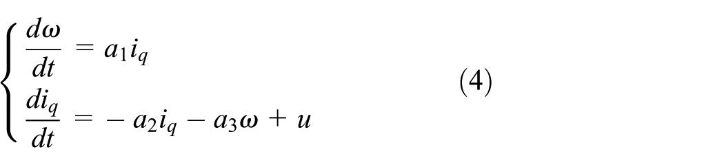
Assume that the magnetic circuit is unsaturated. Hysteresis and eddy current loss are ignored, and the distribution of the magnetic field is in sine space. Under this condition, the mathematical model of a surface-mounted PMSM in the d–q frame can be described as 32

where
Usually, for the purpose of eliminating the coupling between the angular velocity and currents, the d-axis reference

Denote
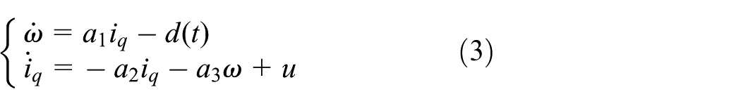
According to equation (3), the single-loop structure of PMSM can be designed as follows (Figure 1).

The principle block diagram of PMSM system based on the single-loop structure.
In real industrial applications, the q-axis current of PMSM needs to be limited into a certain range, namely,
Controller design
The control objective is to design an error feedback controller such that the speed
The finite-time current-constrained controller
At first, PMSM control system in the absence of the load torque is considered
Denote

with current constraint
A finite-time current-constrained controller for system (5) is designed as
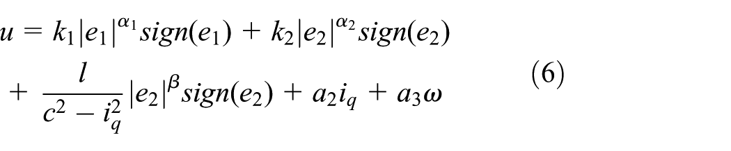
where
Stability analysis
Lemma 1
Suppose that system
Theorem 1
If the initial value
Proof
A Lyapunov function candidate is constructed as

Taking the first derivative of
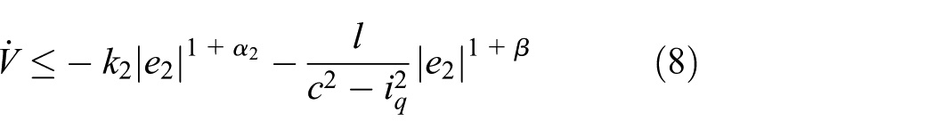
If
In fact

Denote error systems (5) and (6) as

where
On one hand, it is easy to verify that system

is homogeneous with degree
On the other hand, in order to ensure

holds uniformly for

A sufficient condition is
According to the above analysis and applying to Lemma 1, error systems (5) and (6) are locally finite-time stable. At the same time, the state constraint is satisfied. This completes the proof.
GPIO design
In practical application, the load torque has to be taken into account. For this case

with the q-axis current constraint
Combining the speed loop and current loop together, the equation of motion can be written as follows

where
In order to achieve a good anti-disturbance performance, a GPIO is utilized for the single-loop control system of PMSM. The detailed principle of GPIO can be found in the study of Sira-Ramirez and Oliver-Salazar. 35
Here, a fourth-order GPIO can be designed as follows
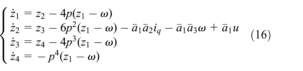
where
Composite control design
A composite control law (finite-time current-constrained controller + compensation based on GPIO) for the single-loop structure of PMSM is then designed as follows (Figure 2)


The block diagram of the single-loop structure based on the composite controller.
The block diagram of the single-loop structure based on the designed composite controller is shown in Figure 2. Here, GPIO in the feedback path provides an estimate of the unknown lumped disturbances. The estimate of disturbances is employed for the feed-forward design of the control law such that the performance degradation caused by the disturbances can be suppressed. Then, we design a feedback control law using a finite-time current-constrained control technique. Our method can be considered as a composition of finite-time current-constrained feedback plus feed-forward compensation based on GPIO.
In debugging process, tuning
Remark 1
According to Figure 3, when

The variation of differential gain when
Simulation and experiment
The specification of PMSM both in simulations and experiments are the same which is given in Table 1.
Specification of the PMSM.
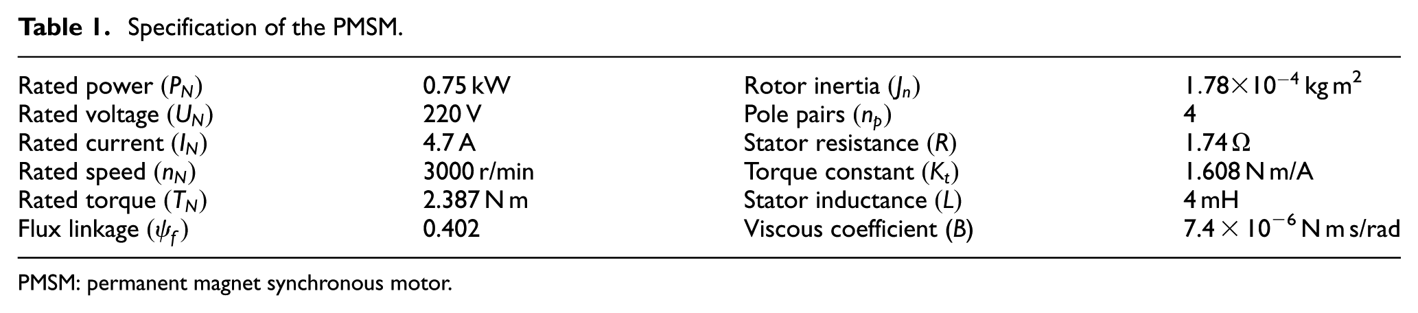
PMSM: permanent magnet synchronous motor.
Simulation results
To evaluate the performance of the proposed method, simulation on PMSM has been performed. The control parameters of the simulation in this article are shown in Table 2. To have a fair comparison, the control outputs of all algorithms have the same saturation limits. Simulation results are shown in Figures 4–7, where the dynamic and steady state curves are correspondingly shown in partial enlarged drawings.
Control parameters of simulation.

PID: proportional–integral–derivative; GPIO: generalized proportional integral observer.

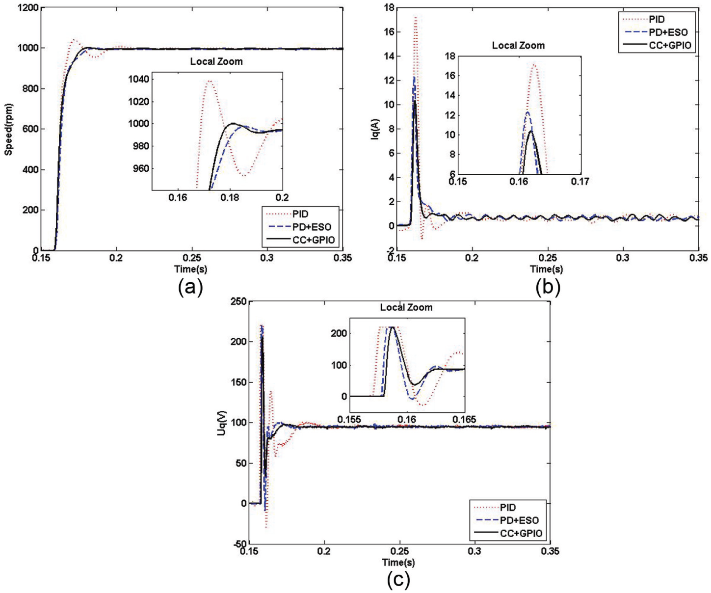
Performance comparisons at the startup stage (simulation): (a) speed response curves, (b) q-axis current response curves, and (c)

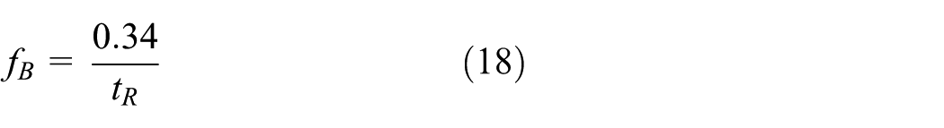
Performance comparisons with step load (simulation): (a) speed response curves, (b) q-axis current response curves, and (c)

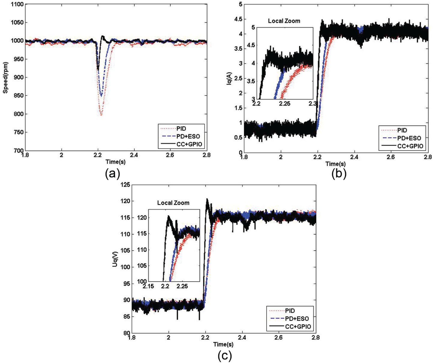
Performance comparisons with ramp load (simulation): (a) speed response curves, (b) q-axis current response curves, and (c)
Performance comparisons with sinusoidal disturbance (simulation): (a) speed response curves, (b) q-axis current response curves, and (c)
Case 1: performance comparisons at the startup stage
Figure 4(a)–(c) shows the response curves of speed,
Case 2: performance comparisons with step load
Figure 5(a)–(c) shows the response curves of speed,
Case 3: performance comparisons with ramp load
Figure 6(a)–(c) shows the response curves of speed,
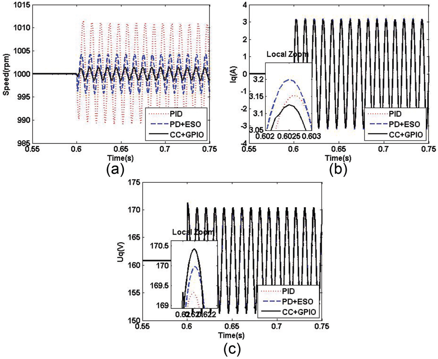
Case 4: performance comparisons with sinusoidal disturbance (frequency = 100 Hz)
Figure 7(a)–(c) shows the response curves of speed,
Experimental results
For the purpose of verifying the performance of simulation, the experimental setup system for PMSM has been built. The experimental test setup is shown in Figure 8. The whole speed control algorithms, including the PID control and the proposed composite control, are implemented by dSPACE DS1104 controller board. The DS1104 is specifically designed for the development of high-speed multivariable digital controllers and real-time simulations in various fields. It is a complete real-time control system based on a 603 PowerPC floating-point processor running at 250 MHz and offers a four-channel 16-bit (multiplexed) analog-to-digital converter (ADC) and four 12-bit ADC units. The power driving circuit is composed of single-phase of diode bridge rectifier, large capacitor filter, and insulated-gate bipolar transistor (IGBT) inverter. The current and voltage signals are detected by Hall sensors, and an incremental encoder is used to obtain the PMSM speed and position. The overall time required for execution of control algorithm is 83 µs. The sampling frequency is 10 kHz, and the pulse-width modulation (PWM) switching frequency is 8 kHz. The control parameters of the experiment in this article are shown in Table 3.
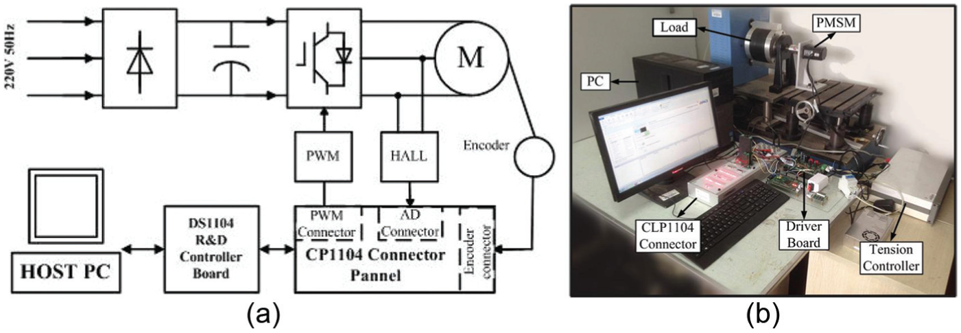
Experimental system: (a) configuration and (b) setup.
Control parameters of experiment.

PID: proportional–integral–differential; GPIO: generalized proportional integral observer.
Case 1: performance comparisons at the startup stage
Figure 9(a)–(c) shows the response curves of speed,
Performance comparisons at the startup stage (experiment): (a) speed response curves, (b) q-axis current response curves, and (c)
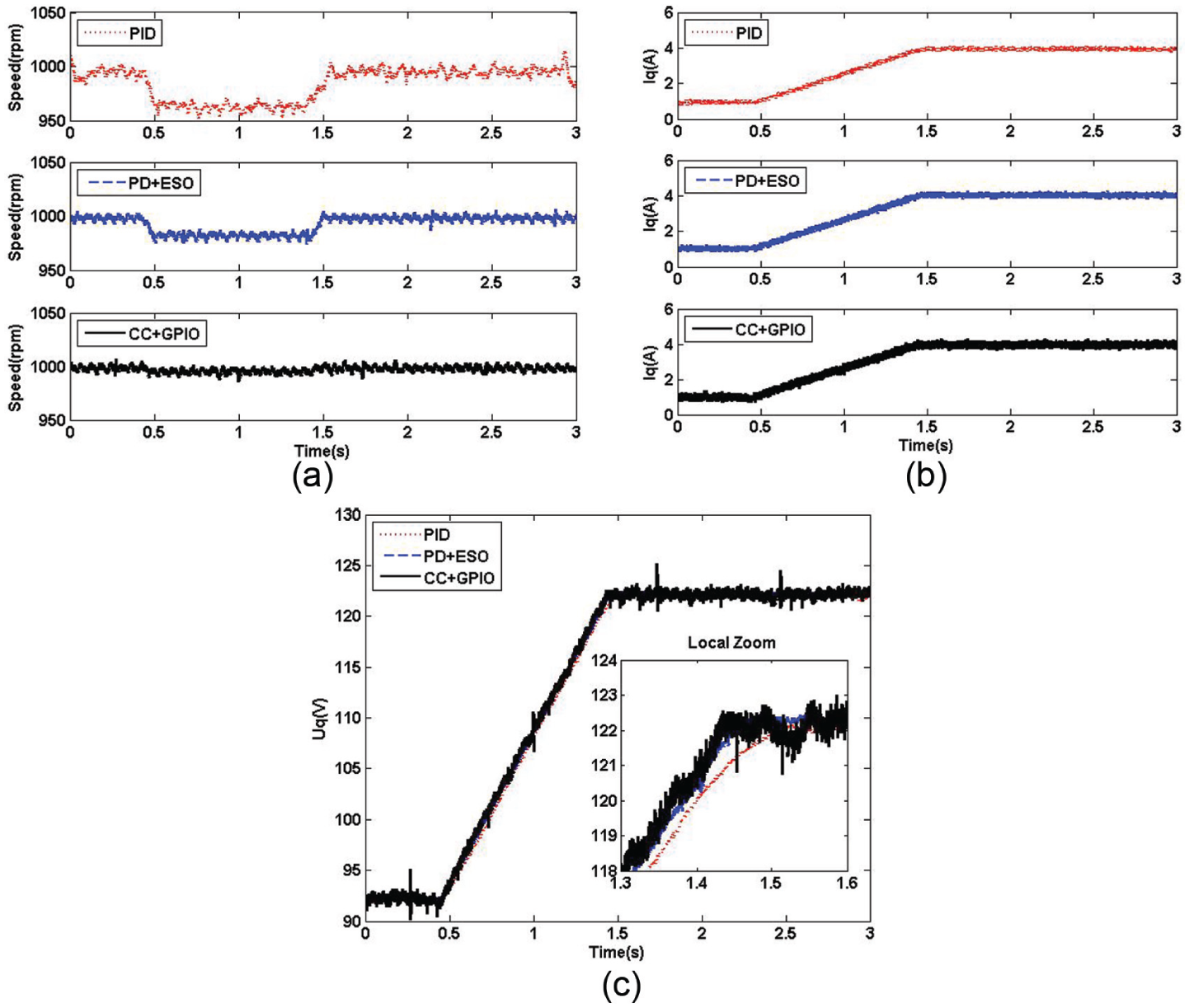
Practical bandwidth was also used as an indicator of the speed control performance. 36 The equation can be described as follows
where
And according to the requirement of current limitation (10.5 A), the composite controller still has an ability to limit
Case 2: performance comparisons with step load
Figure 10(a)–(c) shows the response curves of speed,
Performance comparisons with step load (experiment): (a) speed response curves, (b) q-axis current response curves, and (c)
Case 3: performance comparisons with ramp load
Figure 11(a)–(c) shows the response curves of speed,
Performance comparisons with ramp load (experiment): (a) speed response curves, (b) q-axis current response curves, and (c)
Case 4: performance comparisons with sinusoidal disturbance (frequency = 100 Hz)
Figure 12(a)–(c) shows the response curves of speed,

Performance comparisons with sinusoidal disturbance (experiment): (a) speed response curves, (b) q-axis current response curves, and (c)
According to both simulations and experiments, the composite controller can not only avoid overlarge current effectively but also show a strong ability to reject various disturbances.
Conclusion
In this article, the problems of overlarge current protection and anti-disturbance in the speed regulation of PMSM under a single-loop structure have been discussed. At first, a new finite-time current-constrained controller has been proposed to limit the q-axis current into a safe zone and prevent damage of hardware from overlarge current. Compared to the conventional PID controller, the finite-time current-constrained controller has better disturbance rejection properties and faster convergence performances around equilibrium points. Then, by taking the diversity of disturbances into consideration, a GPIO has been employed to estimate the lumped time-varying disturbances. The estimated value has been used in the feed-forward compensation design to improve the capability of system anti-disturbance. Simulation and experimental results have been given to show the effectiveness of the proposed control method.
Footnotes
Academic Editor: Chenguang Yang
Declaration of conflicting interests
The author(s) declared no potential conflicts of interest with respect to the research, authorship, and/or publication of this article.
Funding
The author(s) disclosed receipt of the following financial support for the research, authorship, and/or publication of this article: The research is supported by National Natural Science Foundation (NNSF) of China under grants (61473080, 61573099) and Program for Science Foundation for Distinguished Young Scholars of Jiangsu Province (BK20130018), China.