
Abstract
An experimental study on the thermal performance of slit-glazed collectors was conducted. Here, glass panes were used as slit glazing cover, and the air was blown continuously through the gaps between them by fan (slit glazing is an uncomplicated and economical process compared to glass perforation). In this study, the effect of the width of glass panes, the distance between the slits, and mass flow rates were studied on three slit-glazed collectors. A glass pane with the length of 131 cm and thickness 0.4 cm was studied for three different slit widths: 6, 5, and 4 cm. The experiments are conducted with four different gap distances between the glass panes (0.5, 1, 2, and 3 mm) and three air mass flow rates (0.014, 0.022, and 0.029 kg/s). The experimental results indicated that the maximum thermal efficiency of 75% was obtained when the gap distance was 0.5 mm, slit width was 4 cm, and the mass flow rate was 0.029 kg/s. The maximum rise in air temperature was noted as 28°C when the gap distance and slit widths were 0.5 mm and 5 cm, respectively. Hence, the best thermal performance was achieved with the smallest slit width and gap distance parameter values.
Introduction
Solar energy can be converted to thermal energy by employing solar collectors. The main features of the solar air heaters (SAHs) are being inexpensive and having a long life, owing to their inherent simplicity. The applications of solar energy to heat fluids include drying vegetables, fruits, foods, and egg incubation among other industrial uses.
1
SAHs used with photovoltaic (PV) system (known as photovoltaic–thermal
Numerous studies have been performed in order to reduce the heat transfer losses from the collector by considering different materials of the cover plate. Hence, SAHs can be classified according to the material of cover plate as glazed collectors (GCs) and unglazed collectors (UCs). In GCs, the sun rays pass through the cover plate and are absorbed by the absorber plate which is placed between the cover plate and bottom. The amount of heat convection loss from glazed solar air heater (GSAH) is less compared to the unglazed collectors due to lower surface temperature.
An analysis conducted by removing insulation from the top and bottom of a two-glazed system, where air is allowed to flow by natural convection, shows that if no insulation is used in the top channel, the efficiency of lower channel would not reduce by more than 5% compared to the case where air is stagnant in the top channel and there is no natural flow. 3 The GCs with double glass covers and fins placed on the absorber plate have the most effective performance compared to the single glass collectors without fins. 4 It has also been observed that by raising recycle proportion (R) from 0 to 2, the thermal efficiency of a double-pass wire mesh–packed SAH improves. 5 Different designs of the absorber plate, such as roughened multi V-rib with gap roughness, 6 protrusions, 7 roughened with rib-grooved, 8 W-shaped ribs, 9 discrete V-down ribs,10–12 multiple v-rib, 13 multi-gap and V-down rib combined with staggered ribs, 14 wavy finned, 15 U-shaped turbulators, 16 V-baffle vortex generators, 17 and V-corrugated plate in the double-pass configuration 18 have been studied.
Unglazed transpired collectors (UTCs) have emerged as a simple yet efficient technology. A flat transpired SAH comprises an unglazed perforated absorbing plate. The heat transfer to air flow in the substrate is drawn through a fan via several small perforations. The concept of UTC was developed in the late 1990s by Christensen et al. 19 Their experimental results indicated that the UTCs cost 70% compared to the SAHs. A numerical study on UTC 20 showed a high thermal efficiency and low temperature rise for lower mass flow rates. A theoretical study without 21 and with 22 the effect of wind velocity is also undertaken. It has been found 23 that the effect of the conductivity on unglazed plate is small. The results 24 show that UTC performs reasonably well when connected to a dryer compared to when the dryer is heated by oil. In this numerical model, the most effective collector heat exchange was obtained 80% for a perforation diameter being 0.8 mm and pitch 0.12 mm. The highest thermal efficiency achieved is 65% for the highest mass flow rate and solar radiation. 25 The results of a theoretical prescription assessing the energy-saving potential of UTC in northern China 26 were found to be satisfactory. The results of a mathematical study on the heat exchange effectiveness of a UTC demonstrated that the maximum percentage rise in temperature of the perforated plate is 62%, 28%, and 10%, respectively, for the front surface, hole, and back side of the cover plate. 27 In an experimental and numerical study on a UTC, with a uniform wind speed distribution, the coefficients of effectiveness and convective heat transfer were 50% and 20%, respectively, (overestimate and underestimate) compared to the actual wind distribution. 28 A computational fluid dynamics (CFD) model was developed to examine the heat transfer and flow characteristics of a UTC. 29 The numerical domain can be divided into three sections, as introduced by Kutscher. 30 This study modifies the Kutscher model by introducing the back surface as an adiabatic surface. The results for the front and hole regions are in good agreement (within 1%) with the Kutscher model. Moreover, the results demonstrate that employing low-conductivity materials, such as plastics, yields acceptable efficiencies. It was found 31 that the highest efficiency cannot be achieved at low wind speeds. The effect of bed height on the thermal efficiency of UTC is studied experimentally and numerically. It was found that the maximum heat transfer takes place at the front surface and minimum at the back of perforated plate. 32 The study of correlation of heat transfer and effectiveness of UTCs, being corrugated instead of a flat plate, was conducted numerically, and it was found that they do not depend on wind velocity. 33 The effect of different colors of a perforated GC was investigated experimentally by Vaziri et al., 34 and the results indicated that the maximum thermal efficiency was obtained 85% for black. The load due to heating decreases by 6.4% on using UTC instead of a conventional SAH. It is found that UTCs are both aesthetically and financially better compared to conventional SAHs. 35 It is seen that the amount of heat transferred from cross perforation to air increases 40% in comparison to conventional UTC (having round perforation shape). 36 A numerical model was proposed and verified experimentally for an unglazed transpired collector-2stage (UTC-2stage). The first stage is a UTC, and the second one is an inclined transpired collector with a transparent cover. 37 The heat transfer and flow coefficients were calculated both experimentally and numerically on the glazed transpired collector (GTC) with slit perforation instead of round perforation. The results predicted by the numerical model were validated by Kutscher, which indicated that the effective efficiency is 64% and 40%, respectively, at the minimum and maximum volume flow rates. This number increases by increasing volume flow rate up to 160 m3/h and decreases thereafter up to the highest mass flow rate. 38 The main disadvantage of this UTC is the unglazed perforation cover, which leads to greater heat convection losses. Therefore, using a glazed material as cover plate is most suitable for this. High cost and fast deterioration of plastic cover (as Plexiglas) compared to glass make the glass the best option for the cover plate. The deviation between numerical results and experimental results of GTC was obtained 3.6%. 39
To the best of our knowledge, no experimental study has been performed with the slit-glazed collector (SGC). The objective of this investigation was to examine experimentally the effect of different slit widths, gap distances between glass panes, and mass flow rates on the thermal efficiency of an SGC. In an SGC system, the air is preheated by passing through a glazed slit that, in UTC, is done by a perforated glazed slit. It appears that by incorporating this new design of SAH, the advantages of both GC and UC can be combined by incorporating glass as the glazing cover and slit-glazed as semi-transpired, respectively, in order to improve SAH’s thermal performance. In addition, the aim of this study is to construct an inexpensive and an efficient SAH while the same materials employed as in a conventional SAH.
The proposed SAHs use glass panes. Having holes on a glass of different diameters and pitches is uneconomical, so cutting the glass having different widths and arranging them vertically is done in the slit glazed.
Experimental apparatus
Three SGCs were constructed and studied experimentally at Famagusta (35.125N and 33.95E longitudes) in Cyprus. The experiments were performed during daytime under clear conditions between November and December 2015. A schematic view of SGCs is shown in Figure 1. The frames of the SAHs were constructed with plywood having a thickness of 1.5 cm and were painted in matt black.
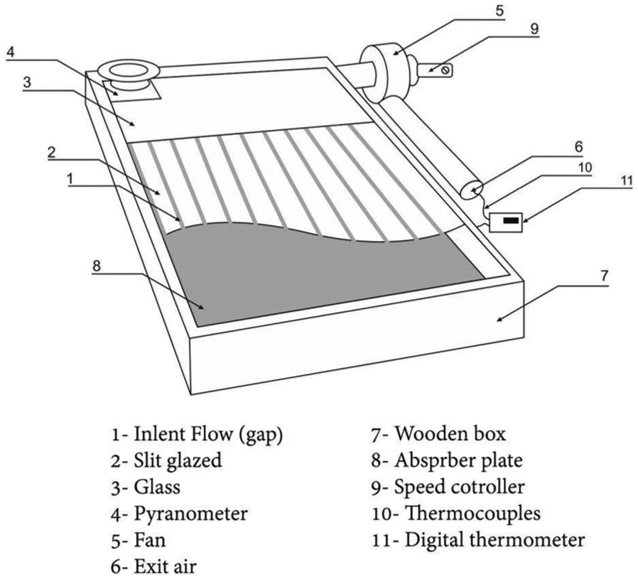
Schematic view of the slit-glazed collector system.
The length and width of each SAH were chosen to be 154 cm and 91 cm, respectively, with a bed height of 7 cm. The sides and bottom of the SGCs were insulated by a 3-cm-thick styrofoam in order to reduce heat losses. A glass pane with the thickness 4 mm, wide 91 cm, and length 23 cm was placed to cover the top part of slit glazing in order to prevent any flow reversals and ensure uniformity in flow. A low carbon steel metal sheet, painted in matt black, of 1-mm thickness was used as absorber plate for each SAH. The glazing cover of the collectors had normal window glass slits of thickness 4 mm, length 131 cm. The experiments were conducted for four different values of gap between the panes, that is, 0.5, 1.0, 2.0, and 3.0 mm; three mass flux rates, that is, 0.014, 0.022, and 0.029 kg/s; and three different slit widths, that is, 4, 5, and 6 cm. At the outlet of each SGC, a radial fan was placed to supply negative pressure in the collector and sucked the heated air into the collector between the glass panes in the slit glazing. The three SGCs so constructed are shown in Figure 2.

Pictorial view of the experimental setup of three slit-glazed solar air heaters.
For each SGC, two type-T thermocouples were employed to measure the inlet and outlet air temperature and the temperature at different points on the glazing. Two-channel digital thermometers with an accuracy of ±1°C were used to measure temperatures hourly during the day. Solar intensity was measured using an Eppley Radiometer Pyranometer (PSP) with a solar radiation meter model HHM1A digital, Omega with 0.25% basic direct current accuracy and a resolution of ±0.5% having a range from 0 to 2800 W/m2. The air velocity was measured using an Extech 407112 Vane anemometer. For the range 0.4–10 m/s, the reading accuracy and data resolution were 0.2 m/s ± 2% and 0.01 m/s, respectively. A dimmer switch was used to control the air flow rate in each collector. The collectors were oriented toward south to capture maximum irradiance and inclined at 39° due to the geographical location of Cyprus.
In this study, efficiency is defined as

where
Uncertainty evaluation
In this section, the uncertainty of the air mass flow rate and thermal efficiency are discussed. The mass flow rate is determined as

where ρ is the air density, V is the outlet air velocity, and A is the cross-sectional area of the outlet. The fractional uncertainty,

where
The fractional uncertainty in the efficiency can be found as
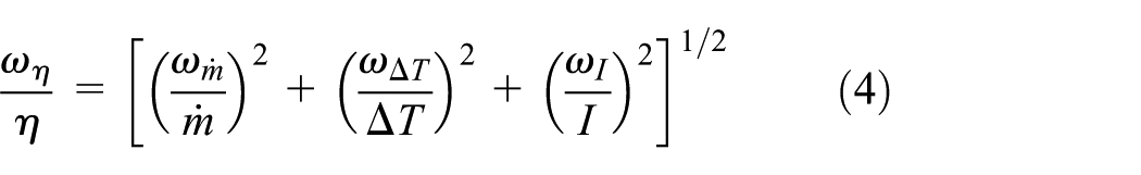
The uncertainties within the thermal efficiency and mass flow rate for the highest air mass flow rate were calculated to be 3.7% and 1.45%, respectively.
Results of experiment
The variations in solar intensity and the inlet temperature were measured on all working days. Since the results indicated a minor fluctuation in the corresponding curves for different days, a mean value for all the working days was considered. Figure 3 illustrates the variations in ambient temperature and solar radiation during day hours.
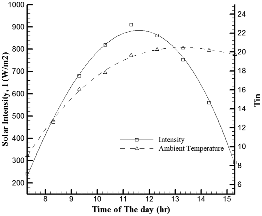
Hourly variation of solar intensity and inlet temperature.
Typically, the solar intensity increased steadily in the morning hours, peaked at midday, and reduced thereafter. The maximum solar radiation intensity was noted at 11:30 a.m. as 923.83 W/m2, and the mean value was 621.16 W/m2.
It is known, in general, that the ambient temperature rises during the day till afternoon. The maximum inlet temperature was measured as 23°C at 01:30 p.m. The rise in the temperature

Temperature rise versus time for a gap distance 0.5 mm; mass flow rates 0.014, 0.022, and 0.029 kg/s; and slit widths 6, 5, and 4 cm.
Figure 4 shows that for a gap distance of 0.5 mm, the maximum ΔT is 28°C with the smallest slit width of 4 cm and the lowest mass flow rate of 0.014 kg/s. Similarly, Figure 5 shows that for a gap distance of 1 mm, the maximum

Plot of temperature rise versus time for a gap distance 1 mm; mass flow rates 0.014, 0.022, and 0.029 kg/s; and slit widths 6, 5, and 4 cm.
By increasing the gap distance to 2 mm (Figure 6),
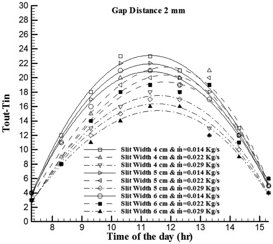
Temperature rise versus time for a gap distance 2 mm; mass flow rates 0.014, 0.022, and 0.029 kg/s; and slit widths 6, 5, and 4 cm.
In the last case as well, for a gap distance of 3 mm (Figure 7), the maximum

Temperature rise versus time at gap distance 3 mm; mass flow rates 0.029, 0.022, and 0.014 kg/s; and slit widths 6, 5, and 4 cm.
In general, Tout − Tin reduces with the increasing mass flow rate. The thermal efficiency of SGC was investigated for the different values of gap distance, slit width, and air mass flow rate. For 0.5-mm gap distance, the maximum efficiency was obtained as 75% for slit width and air mass flow rates of 4 cm and 0.029 kg/s, respectively. The highest thermal efficiency, for slit widths 5 and 6 cm, was noted as 75% and 71%, respectively (Figure 8). The average value of efficiency was 57%, 54%, and 52% for the slit widths of 4, 5, and 6 cm, respectively. As flow friction increases at lower gap distance, the inlet air contact region with slit glazed is also increased. Thus, convective and radiation losses decreased at smaller gap distance. In addition, the heat gain in the working fluid due convection from the slits is increased by increasing inlet velocity. Therefore, it is expected to have higher ΔT at smaller gap distance.

Thermal efficiency versus time for a gap distance 0.5 mm; mass flow rates 0.014, 0.022, and 0.029 kg/s; and slit widths 6, 5, and 4 cm.
For 1-mm gap distance, the highest thermal efficiency was obtained as 70%, 65%, and 65%, when slit widths were 4, 5, and 6 cm, respectively (Figure 9). It should be noted that highest thermal efficiency for each slit width occurred when the mass flow rate was maximum, that is, 0.029 kg/s. The mean values of thermal efficiency were 53%, 50%, and 48%, respectively, at the slit widths of 4, 5, and 6 cm.

Thermal efficiency versus time for a gap distance 1 mm; mass flow rates 0.014, 0.022, and 0.029 kg/s; and slit widths 6, 5, and 4 cm.
By increasing the gap distance from 1 to 2 mm, the thermal efficiency increased for each slit width. The maximum thermal efficiencies were achieved as 60%, 57%, and 53%, respectively, for slit widths 4, 5, and 6 mm at a maximum air mass flow rate (Figure 10). The results demonstrated that the average values of thermal efficiency for all mass flow rates were 44%, 42%, and 40% at the slit widths of 4, 5, and 6 cm, respectively.
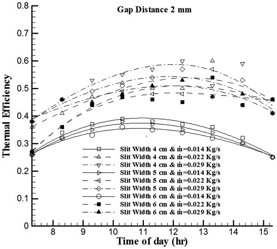
Thermal efficiency versus time at a gap distance 2 mm; mass flow rates 0.014, 0.022, and 0.029 kg/s; and slit widths 6, 5, and 4 cm.
On increasing the gap distance from 2 to 3 mm, the thermal efficiency decreased. The maximum thermal efficiency was observed at 4-cm slit width as 56%, which decreased to 51% for both the slit widths, 5 and 6 cm (Figure 11). The average values of efficiency for the slit widths of 4, 5, and 6 cm were obtained as 42%, 40%, and 38%, respectively.

Thermal efficiency versus time for a gap distance 3 mm; mass flow rates 0.014, 0.022, and 0.029 kg/s; and slit widths 6, 5, and 4 cm.
The results show that the thermal efficiency is considerably influenced by the ambient temperature, and it increases with increasing ambient temperature. The amount of heat loss from the collectors to the ambient is higher in the mornings compared to afternoons as the ambient temperature is lower in the mornings.
The variation between (Tair−Tamb)/I versus thermal efficiency are presented in Figure 12. The results demonstrated that thermal efficiency and slope of the thermal efficiency versus (Tair−Tamb)/I increased by increasing mass flow rates. Here, the results of more efficient gap distance, 0.5 mm, are presented. Similar results were found in other experimental investigations.34,41,42
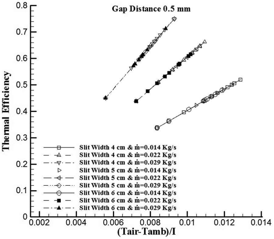
Thermal efficiency versus (Tair−Tamb)/I at gap distance 0.50 mm; mass flow rates 0.014, 0.022, and 0.029 kg/s; and slit widths 6, 5, and 4 cm.
Conclusion
The thermal performance of three SGCs was investigated experimentally for different gap distances, air mass flow rates, and slit widths. A new design for SAH is suggested in this study so as to reduce the glazing heat losses that are found in a conventional SAH. Glass panes are easy to obtain and are cost effective compared to the perforated glazed ones.
The results showed that the thermal efficiency increased with an increasing air mass flow rate. The maximum temperature rise was noted at 28°C for a gap distance of 0.5 mm, slit width of 4 cm, and the lowest air mass flow rate of 0.014 kg/s. The maximum efficiency of 75% was obtained for a slit width of 4 cm, a lowest gap distance of 0.5 mm, and maximum air mass flow rate of 0.029 kg/s. The efficiency improved substantially when slit glazing was introduced compared to a conventional SAH which is varied between 29% and 40%. 43 Summarizing, for each slit width, the best performance was achieved at the lowest gap distances and highest mass flow rates.
Footnotes
Academic Editor: Hua Meng
Declaration of conflicting interests
The author(s) declared no potential conflicts of interest with respect to the research, authorship, and/or publication of this article.
Funding
The author(s) received no financial support for the research, authorship, and/or publication of this article.