
Abstract
This article analyzes the dynamics of a ship-mounted crane and establishes the mathematical model of the load. Based on the mathematical model, the time-delayed feedback control algorithm is proposed to anti-load sway. The Lambert W function and Newton–Raphson method are used to prove the stability of control system. The contour plot of the system damping is obtained; by selecting appropriate time delay and system gain, the system damping increases and load sway rapidly decays, thereby the system is stable. The co-simulation and experimental results show that the delayed feedback controller has better performance in anti-sway and robustness.
Introduction
Ship-mounted cranes, which transfer loads using a rotary crane attached to the ship’s deck, are widely used to transfer cargos from ships to the harbor, or between two ships. The rotary cranes transfer loads by three motions: rotation, luffing, and load hoisting. In addition, there are still many issues in the performance of rotary cranes, such as load sway, positioning, and obstacle avoidance. The ship-mounted crane is more difficult to operate under the influence of the ship sway. Ship sway is generated by disturbances such as waves and winds, as well as movements of the load. During the transfer operation, the operator has to deal with the sway of the ship.
The main objectives of crane control research are to reduce or eliminate residual vibrations at the end of maneuvers, reduce maneuvering time, and enhance safe operating conditions. Researchers used many techniques to achieve these goals. 1 Input-shaping is one of the common control techniques. Parker et al. 2 present command-shaping approaches to reduce the operator-induced payload swing for a ship crane. Alhazza and colleagues,3,4 focusing on the overhead crane, design a novel wave form command shaper of adjustable maneuvering time, which can effectively reduce load vibrations in intermittent maneuvers. Shen et al. 5 provide a straight transfer transformation (STT) model to control the rotary crane. The proposed STT model can effectively eliminate the influence of centrifugal force. However, the input shaping and optimum control algorithm mentioned are open-loop control. This kind of method is sensitive to the change of system parameters. Besides, it also orders an end previously, but in actual engineer, the end is often adjusted by the operators.
With the rapid development of automatic control and artificial intelligence, various intelligent control techniques are applied to the robotic system.6–11 For the open-loop control strategy is sensitive to initial disturbances, the closed-loop control and advanced intelligent techniques are also designed to control the vibrations of crane.12,13
Sun et al. 14 propose a nonlinear stabilizing control law for a ship-mounted crane; it is the first closed-loop control method without simplifying the original complex nonlinear dynamics, which can effectively control a ship-mounted crane with ship rolling and heaving movement. Tuan et al. 15 design a nonlinear feedback controller for a shipboard container crane, in which the influence of wave and the flexibility of the cable are considered.
Park et al. 16 design an adaptive sliding-mode controller and a fuzzy observer for an overhead crane with high-speed hoisting motion. The results show that the proposed control law is valid. Tuan et al. 15 propose a back-stepping sliding-mode controller for a ship-mounted container crane. The dynamic model of the crane system considers the seawater disturbance and wire flexibility. The simulation results show that the proposed control strategy can significantly reduce the cargo vibration. Aksjonov et al. 17 use Euler–Lagrange state-space approach to derive the mathematical model of a three-dimensional crane and design an anti-swing fuzzy logic controller to the crane. The results show that the positioning in fuzzy logic controller has an error, and it is still more stable and accurate compared to traditional proportional–integral (PI) controller.
This article, first, abstracts the actual crane system and then derivates the mathematical model of the rotary crane. It gets a mathematical model of the ship-mounted crane by coordination transformation. To simplify the nonlinear system into a linear system and optimize the process of stability analysis, this article proposes a time-delay feedback anti-swing control algorithm of the ship-mounted crane. Applying Lambert’s W function and Newton–Raphson algorithm to the stability analysis of the crane, it can get the right eigenvalue of the system’s differential equation and draw the damping contour of the system. From this chart, reasonable delay time and gain make swing of load decline quickly and stabilize the system as soon as possible.
Modeling of ship-mounted crane
The model of the ship-mounted crane comprised two parts: the load sway model and the mathematical model.
Load sway model
For simplicity, the following assumptions were made:
The body of the boom crane can be regarded as a rigid body, and the backlash of the boom and crane is neglected.
The load can be seen as a particle.
Frictional torque that may exist in torque-transfer mechanisms can be neglected.
Weight and elongation of ropes, due to tensile force, are neglected.
In order to derive the load sway model, the swing angle of the load is observed. A schematic diagram of the boom crane is shown in Figure 1. (

Schematic diagram of a boom crane.
The in-plane and out-of-plane angles of the payload are, respectively, represented by

The inertial position

The position of P in the crane coordinate system

We use the Lagrange approach to derive the equations of motion. It follows from Figure 1 that the Lagrange’s equations are given by
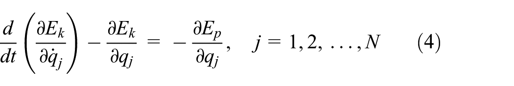
where
In this article, combined with the dynamic model of the boom crane, set lifting point mass is M, and the load mass is m, we have

Substituting equation (5) into equation (4), the swing equation of the load Q is expressed as
where
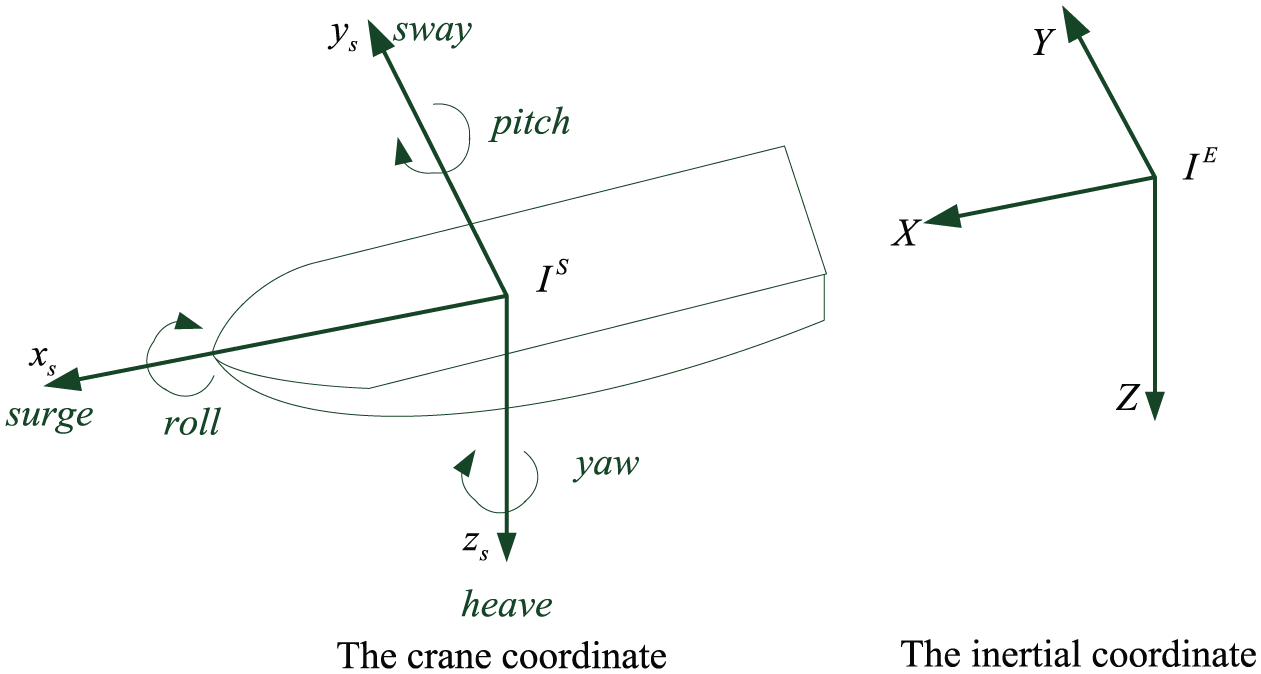
Ship-mounted crane model
To accurately describe the dynamic model of the ship-mounted crane, the inertial coordinate system
Ship-mounted crane coordinate system.
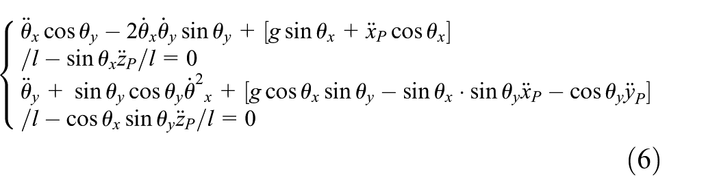
Taking into account the ship’s dynamic positioning, we can ignore the surge, sway, and yaw, while only consider the roll, pitch, and heave.12,18 So, the coordinates of suspension point P with respect to the inertial moment are given by equation (7)

where
Figure 3 shows the ship-mounted crane model diagram, where crane model is equation (3),

Ship-mounted crane model diagram.
Time-delayed feedback control system
Time-delayed feedback
Time-delayed feedback anti-sway control is a nonlinear feedback control method by introducing a time delay to the output of the system, 19 and it will produce damping in the system response; consequently, that can significantly suppress the oscillation amplitude of payload for a ship-mounted crane, and the time-delay control law takes the following form

where
Stability analysis
While the roots of the characteristic equation of the linear system are in the left half s-plane, the system is asymptotic stable. For the relationship between the stability of the nonlinear system and the linearization system, Lyapunov proved very important conclusions:
If the linear approximation of nonlinear system is strictly stable, namely, all the roots are in the left half s-plane, then the nonlinear system will stabilize at a certain neighborhood of the equilibrium point of the linear approximation.
If the linear approximation of nonlinear systems has one root in the right half s-plane, then the nonlinear system cannot be stable at any neighborhood of the equilibrium point of the linear approximation.
According to this corollary, the article linearized and decoupled the control system nearby the equilibrium point, and analyzed the stability of the ship-mounted crane using the characteristic root method. From equation (6), the load swing has the characteristic of strongly couple and nonlinear; to linear it, we scale the system variables into fast-varying and slow-varying terms, where

and the slow-varying terms are

Substituting equations (8)–(10) into equation (6), and letting the coefficient of


where
From equation (11), the highest-order derivative of the differential equation also includes time-delay; this equation is called the neutral delay differential equation, which is of the form

To analyze the characteristic roots of delay differential equations, while DDE-Biftool mathematical tools were used, we can get its characteristic roots. But neutral differential equations are different, and its rightmost characteristic roots cannot be directly solved using the most of the existing mathematical tools. Usually, we set the solution of equation (11) as follows

Substituting equation (14) into equation (11) and setting each coefficient of
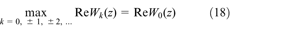
This article presents a novel algorithm, which applied the combination of the Lambert W function 19 and Newton–Raphson algorithm to analyze the stability of ship-mounted crane. This method not only simplifies the calculation process but also directly solves differential equations’ rightmost characteristic roots, and further judging the system stability. The characteristic equation of (13) is

where

If
Numerical solution
Based on the Lambert W function, it can give stability boundary of equation (11). The Lambert W function cannot be represented by elementary functions, but represented by the following transcendental equation

where
By means of the above nature, the biggest real characteristic roots can be solved. Three mathematical software (MATLAB, Maple, and Mathematica) can directly calculate the Lambert W function. The calculation of solving the rightmost root’s real part of equation (11) is as follows.
We let

Using Lambert W function, the implicit solution of

Substituting the gain

The iterative formula is the second-order convergence. The Halley method can also be used, and the core iterative formula of the method is given by

The iterative formula is the third-order convergence, and the higher the order of convergence, the faster the convergence. Setting tolerance

The iteration is terminated, and

Substituting different
Figure 4 is the iterative process of real part and imaginary part of characteristic root

The real part and imaginary part of the characteristic root
Let

The largest real part of characteristic root for
Let

The largest real part of characteristic root for
The damping of the time-delay control system of ship-mounted crane cannot be directly obtained from equation (11), but its value can be judged by the real part of the largest characteristic root

The three-dimensional map of damping.
Figure 8 shows the damping contours about the controller gain k and the time delay

The damping contour about k and τ.
Simulation results
To verify the performance of the proposed control strategy, we carry out some simulations. The dynamic model of ship-mounted crane is developed in section “Modeling of ship-mounted crane” and simulated under complex conditions included the seawater effect and the flexibility of the wire. The dynamic model is established in the MATLAB–Adams environment.
Simulation results without crane active movements
The boom length is

Virtual prototype of crane ship.
Figure 10 is the reference rotary and luffing angles of crane without active movement. When the initial rotary and luffing angles are

Reference luff and slew angles of chip-mounted crane.
Figure 11 is the response of the ship-mounted crane in the presence of ship pitching movement, wherein the solid line is the enabled controller, while the dotted line is not. It is seen from Figure 11 that even in the case of no crane active movements, the position error of payload is larger than that of the proposed method.

Simulation result of the ship-mounted crane with ship pitching.
Simulation results with crane luffing or slewing movements
Ship-mounted crane slewing and luffing movement can be divided into three processes: acceleration, constant speed, and deceleration. In the slewing movement case, the acceleration is 0.05 rad/s2, and the maximum speed reaches 0.1 rad/s after 2 s of acceleration. The parameters of the crane movement are shown in Figure 12.

Motion parameters of ship-mounted crane slewing movement.
Figure 13 shows the solved reference rotary and luffing angles of the crane actuators by the time-delay controller, where all contain slight concussions for artificially introducing time-delay feedback of

Reference angles of chip-mounted crane.
Figure 14 is the response of the ship-mounted crane with slewing and ship pitching, wherein the solid line is the enabled controller, while the dotted line is not. The simulation result shows that the cargo vibration of the controlled crane is reduced significantly while the uncontrolled result shows a large vibration.

Simulation result of the ship-mounted crane with ship pitching.
Experimental result
To further verify the performance of the designed controller. The parameters of scale ship-mounted crane system are as follows: the boom length
Figure 15 is the experiment result of the ship-mounted crane in the presence of ship pitching movement, wherein the solid line is the enabled controller, while the dotted line is not. It is seen from Figure 15 that as in the two simulation cases, the cargo vibration of the controlled crane is reduced significantly to unnoticeable amplitude within 5 s while the uncontrolled experiment result shows a large vibration.
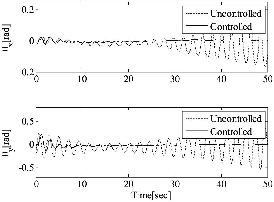
Experimental result of the ship-mounted crane with ship pitching.
Conclusion
This article proposed a time-delayed feedback control strategy for anti-sway control of a ship-mounted crane, proved the stability of the designed system by the combination of Lambert W function and Newton–Raphson methods, drawled the contours of the damping, and selected the appropriate controller parameters. Several test cases were simulated by MATLAB–Adams and validated experimentally on a scaled model of a ship-mounted crane. The co-simulation and experimental results show that the time-delay feedback control law is an effective technique of eliminating cargo vibration for ship-mounted cranes.
Footnotes
Academic Editor: Chenguang Yang
Declaration of conflicting interests
The author(s) declared no potential conflicts of interest with respect to the research, authorship, and/or publication of this article.
Funding
The author(s) disclosed receipt of the following financial support for the research, authorship, and/or publication of this article: This work was supported by the National Natural Science Foundation of China (no. 51375140).