
Abstract
The ship-mounted cranes are widely used to transfer heavy cargos between ships and other transportation devices. This paper proposes a block disturbance observer-based sliding mode control method for suppressing the payload sway and achieving accurate positioning. In particular, the proposed block disturbance observer availably estimates external disturbances due to ship rolling, pitching and heaving for ship-mounted crane systems, and which are fed back to the input as compensation signals. By designing nonlinear sliding surface, the payload can arrive at their desired positions quickly while suppressing the payload swing simultaneously. Simulation and experimental results show the effectiveness of the proposed control scheme. Using this method, oscillations are reduced to less than 10 cm during transfer.
Keywords
Introduction
Ship-mounted cranes are specialized lifting devices installed on ships to handle cargo. As ocean engineering becomes more and more popular and important, the use of ship-mounted cranes has been growing over the past few decades. Consequently, the control problem for ship-mounted cranes has attracted considerable attention.1–5 Ship-mounted cranes belong to the class of underactuated systems, whose control input dimension is less than the degree of freedom dimension. Thus, the mechatronics and control community of underactuated systems have become research hotspots.6–10
The main control objective for ship-mounted cranes is to transport the cargos to the desired location quickly, with negligible payload sway during the transportation process and no residual swing at the end. Due to the inherently underactuated nature of cranes, this problem is very challenging. Over the past few decades, the control issues of land-fixed crane systems are extensively studied by scholars all over the world. Specifically, various closed-loop control methods have been developed, such as delayed position-feedback control), 11 quasi-PID control, 12 partial feedback linearization control, 13 sliding mode control (SMC), 14 and adaptive nonlinear control. 15 Besides, the open-loop control methods including the intelligent optimal control 16 and input shaping control17,18 were often used to satisfy various demands from the industry (e.g., low-cost and user convenience).
Moreover, unlike land-fixed cranes, the ship-mounted cranes are adversely affected by various external disturbances (such as sea waves, sea winds, etc.) due to harsh (sea) working conditions,4,5,19 which makes the control problem extremely challenging. For the past few decades, the study of ship-mounted cranes has achieved great progress.20–25 For ship-mounted tower cranes, a nonlinear feedback controller was investigated in Qian and Fang. 26 For container cranes, observer-based nonlinear robust control and continuous integral sliding mode control approaches were proposed.27–30 For offshore boom cranes, several methods were proposed: time-delayed feedback control algorithm, 31 various energy-based control law,26,32,33 and adaptive control method. 34 What is more, for the unmodeled dynamics and other disturbances, several researchers have presented the active disturbances suppression methods that introduce bounded constants to compensate them.4,19
Due to the analysis above, the control of ship-mounted cranes remains a challenging and unresolved issue. The ship’s motion that caused by sea waves inevitably degrades control performance. Currently, some researchers use a separation methodology for offshore boom cranes,19,22 which involves dividing the crane model into two parts: the crane component and the disturbance component. Unfortunately, this approach fails to address disturbances in the unactuated parts of the crane dynamics, resulting in suboptimal control performance. In addition, the existing literature studies mainly focus on the influence of ship roll and heave motion on ship-mounted cranes. To get closer to the engineering practice, this paper meanwhile considers ship roll, pitch and heave, and does not treat the ship motion as disturbances, and as the new state variables and performing intricate mathematical manipulations, the disturbance component is successfully integrated into the crane dynamics. This eliminates the need for direct analysis of ship motion-related disturbances, greatly simplifying the controller design process. Using this new model, a block disturbance observer-based sliding mode controller is developed for ship-mounted cranes, and the stability of the closed-loop system is analyzed by Lyapunov techniques. Finally, the simulation and experimental results validate the effectiveness of the proposed control method.
The main contributions of this paper can be summarized as follows.
(1) This paper regards the ship roll, pitch and heave motions as a part of the crane dynamics. This process is closer to the actual working conditions of ship-mounted cranes, based on this idea, a novel 5-DOF mathematical model of ship-mounted crane has been established.
(2) For ship-mounted cranes, a new compensated sliding mode control (CSMC) algorithm, which combines block disturbance observer(BDOB) with sliding mode controller, is developed to restrain the payload sway based on decoupling the original mathematical model of ship-mounted crane, and the BDOB is used to address the persistent disturbances caused by ship roll, pitch and heave motions.
The rest of this paper is organized as follows. In Section “Modeling of a ship-mounted crane,” the dynamic model of the ship-mounted crane system is established. In Section “Controller design,” the system dynamics are further reformulated to analyze conveniently, and the sliding mode controller design and corresponding stability are carried out. Section “Design of block disturbance observer” presents the block disturbance observer to compensate the external disturbances. Some comparative experiments are presented to validate the effectiveness of the proposed method in Section “Simulation and experiment.” Section “Conclusions” draws the paper to a conclusion.
Notations
Throughout the paper,
Modeling of a ship-mounted crane
Equation of motion
In the mathematical modeling of the ship-mounted crane, the following assumptions are followed:
The crane is regarded as a rigid body and a particle, and the cable is an inextensible massless cable.
Ignoring the friction torque between various parts of the crane and ignore the air resistance.
Considering the external interference, it is assumed that the ship is a uniform rigid body.
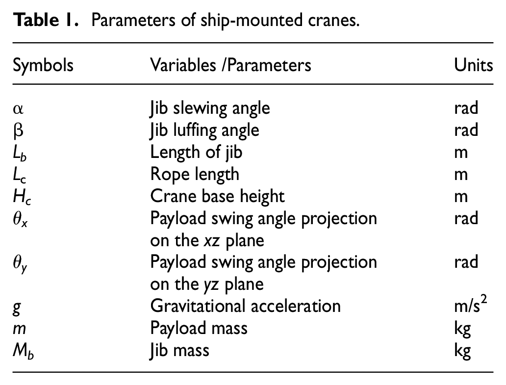
The schematic diagram of ship-mounted crane system is shown in Figure 1, where there are three frames [i.e. the inertial coordinate XOY, the ship coordinate xsosys and crane coordinate xoy], and the corresponding system parameters are illustrated in Table 1. For ship coordinate, xs is parallel to ship deck and points toward the bow, and zs is vertical to ship deck down. The origin of the inertial coordinate O coincides with the origin of the ship coordinate os.
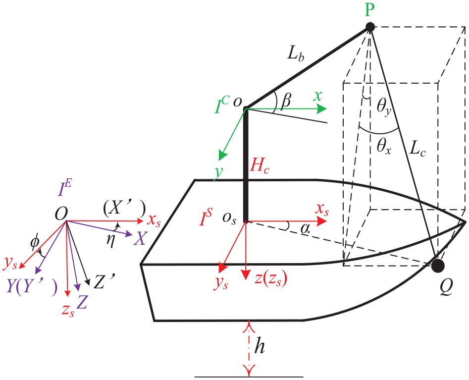
Coordinate frames of a ship-mounted crane.
Parameters of ship-mounted cranes.
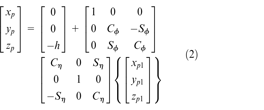
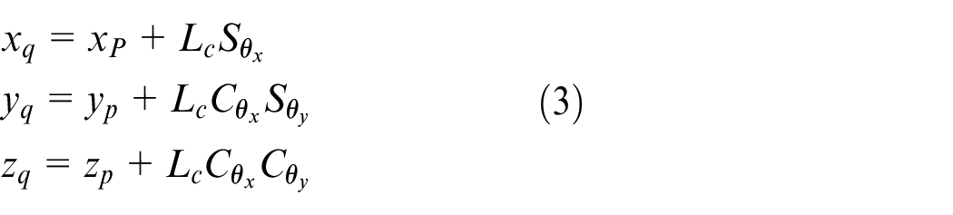
As illustrated in Figure 1, the position of boom tip P
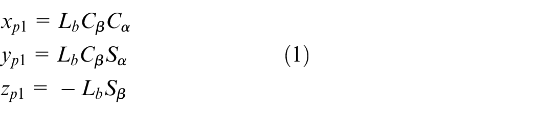
where
The ship motions mainly include the rolling angle
The position of the payload Q
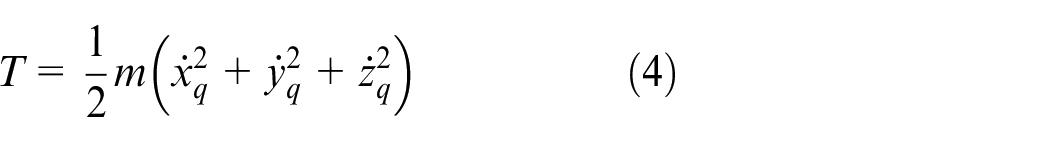
Therefore, the kinetic energy of payload swing caused by system motion and the potential energy of payload are given as follow:

According to the kinetic energy and potential energy of the payload, the Lagrangian L is defined as

For the anti-swing control of the ship-mounted crane, the swing angle and of the crane
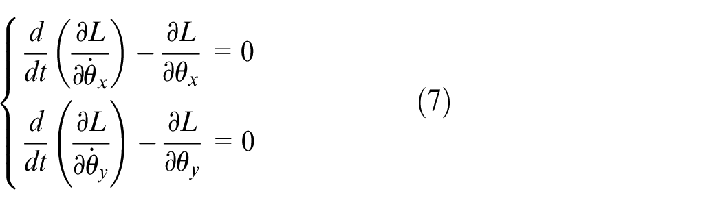
After calculation and sorting, the swing equation of the payload Q is:
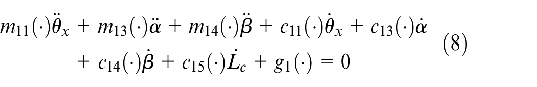
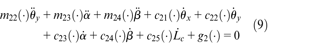
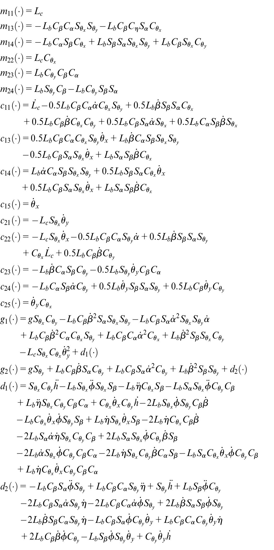
where
In order to obtain the tension in the lift wire, the balance equation of the payload is established in the vertical direction as:

In (10),
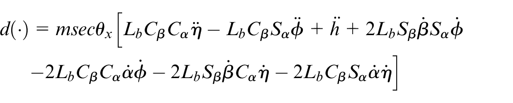
Substituting
where
Motor drive equation
The jib slewing, luffing and the payload lifting movements of the ship-mounted crane are driven by the slewing motor, luffing motor and lifting motor respectively. According to the torque balance equation on the motor output shaft, the differential equation of the motor with torque as input and motor output shaft angle as output is expressed as follows:
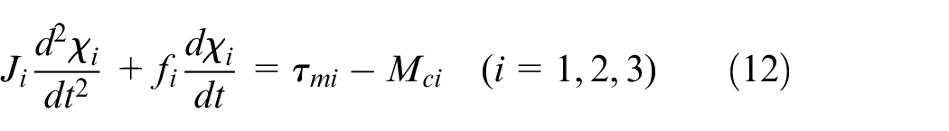
In (12),
For slewing motor, the differential equation is:
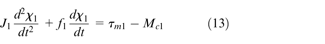
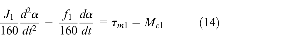
In the crane system, the slewing motor is connected to the boom support through a reducer, and the reduction ratio of the reducer is 160, that is
For luffing motor, the differential equation is:

It is seen obtained from the geometric relationship of l in Figure 2.
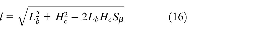
It can be seen from Figure 2 that the relationship between rope length change and motor output angle is
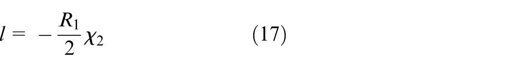
where
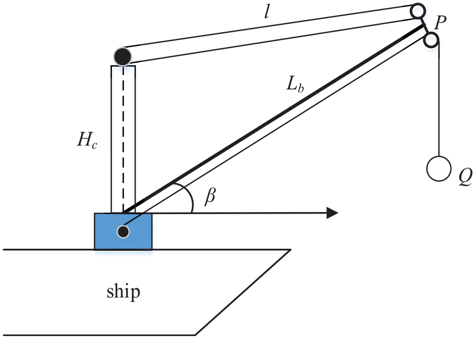
The structure of crane.
Take the derivative of (16) with regard to time and combine (17) to obtain the differential equation of luffing motor expressed in luffing angle
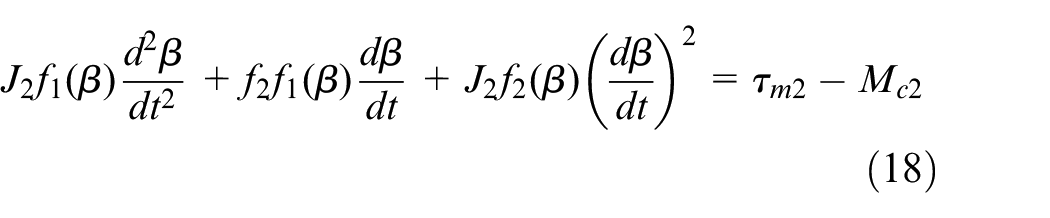
where
For lifting motor
The relationship between the rope length and the output angle of the lifting motor is as follows·
where
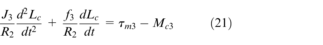
Substituting (20) into (19), the differential equation of the rotating part of the hoisting motor represented by
The load torque of crane slewing, luffing and lifting motors can be expressed as:
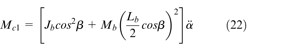
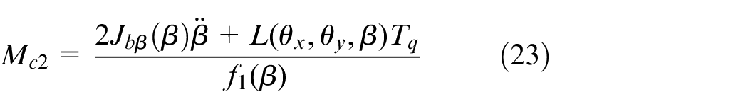

where
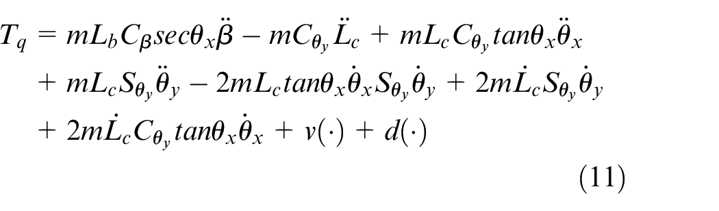
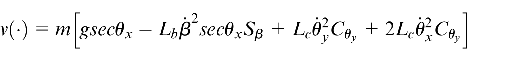
Substituting (22)-(24) into (14), (18) and (21) respectively, and sorting them out:

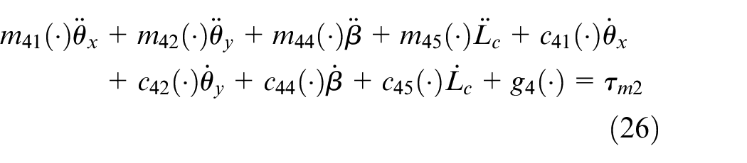
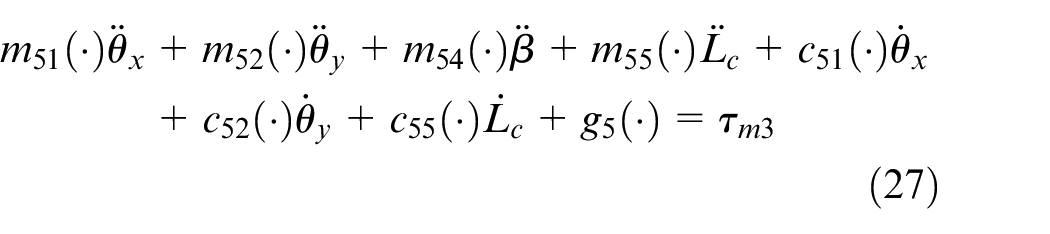
where
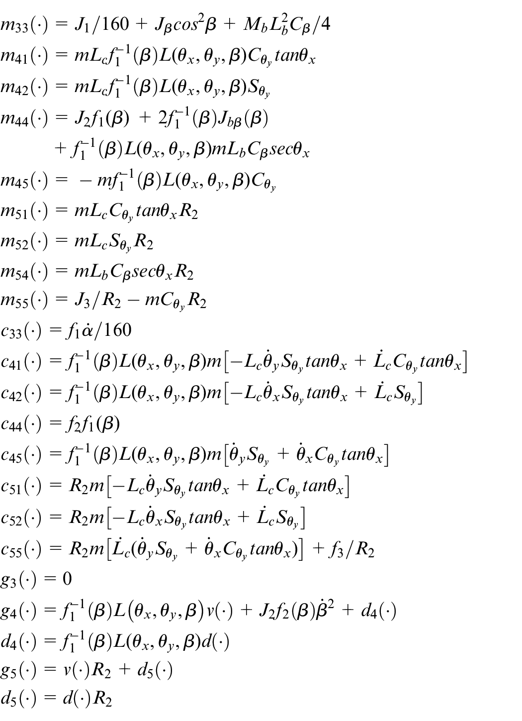
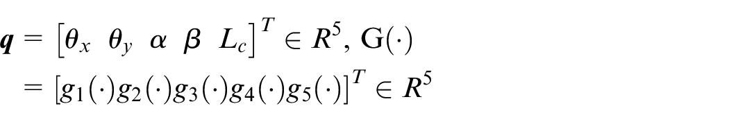
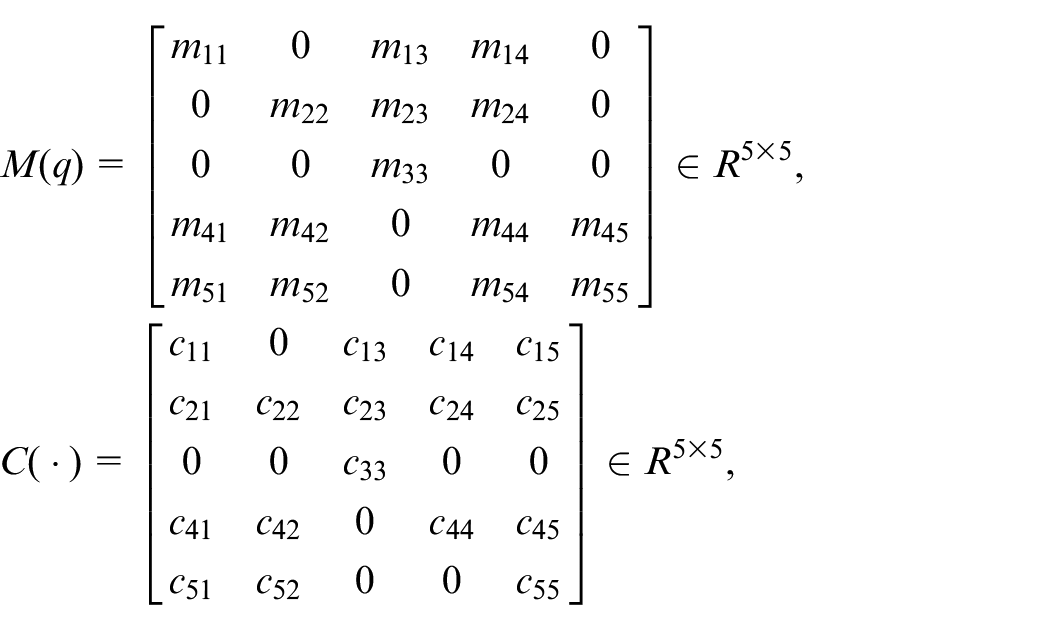
Rewriting (8), (9), (25), (26), and (27) in matrix form, the overall dynamic equation of ship-mounted crane system is obtained as follows:

where
Controller design
Considering the actual working conditions of the ship-mounted crane, the payload will not reach above the boom tip, so there is no special description. The following reasonable assumptions will be made:
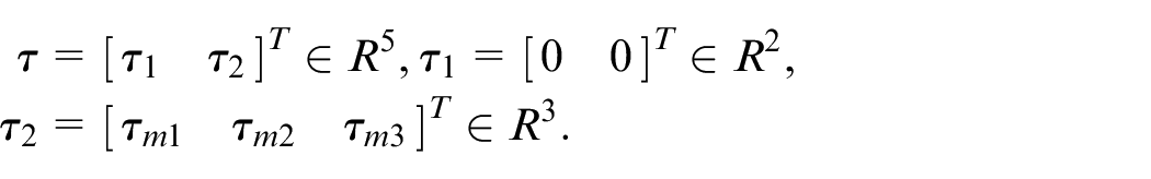
The vector
According to lemma 1, the inertia matrix
Decoupling of ship-mounted crane dynamic equations
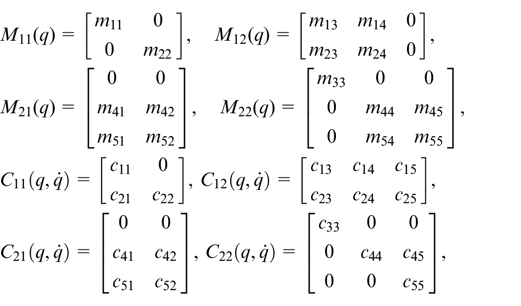
The dynamic equation of ship-mounted crane is shown in (28). It can be seen from the mathematical model that the ship-mounted crane is a typical underactuated system. Generally, the control of underactuated system is complex. Therefore, the mathematical model of ship-mounted crane needs to be decoupled to generate a form more suitable for the controller design of underactuated system. The ship-mounted crane has five control quantities, which are related to five output components respectively. As an underactuated system, five output variables are driven by three input control signals, in which the vector related to the underactuated state is

where,

The feedback signal of the control system includes state variable
The control scheme is mathematically designed to make the driving state
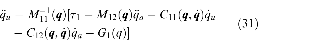
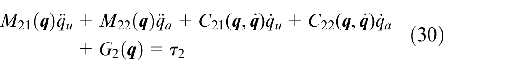
The simplified dynamic model of the system can be obtained by substituting (31) into (30):

where,
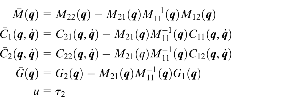
Take
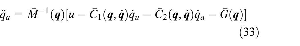
where
Sliding surface design
Let
Define the tracking error vectors
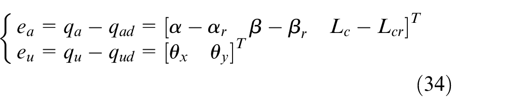
In (34),
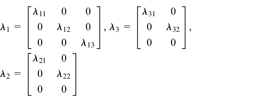
Design the sliding surface

where,
The derivative of (35) shows that the change rate of sliding surface is:

It can be seen from the sliding mode surface that when
Design of sliding mode control law
In order to ensure that the system can asymptotically converge to the sliding mode surface, the sliding mode control law can be designed according to Lyapunov theorem.
Let Lyapunov function be:
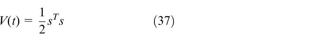
The derivative of V(t) with regard to time is defined as:

According to Lyapunov theorem, the condition of system stability is
Substituting (34) into (36) yields the expression of the change rate of the sliding mode function with regard to each order derivatives of the state vector:
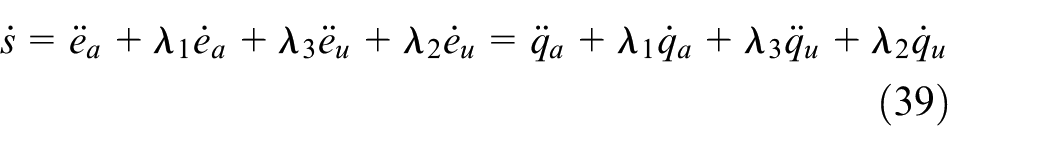
Substituting (31) into (39) yields:
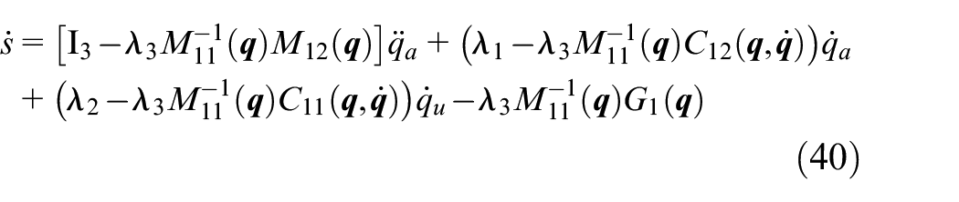
Substituting (33) into (40), it can be further simplified as:
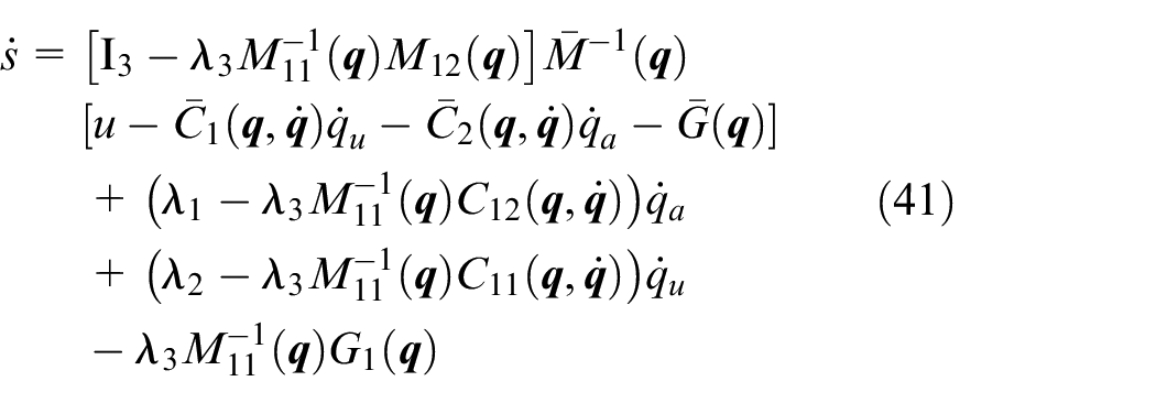
By selecting the control input signal u, the control target can be achieved.

where
Note that by imposing the condition in (42) on s, we guarantee that s converges to zero asymptotically. The control u is chosen as follows:
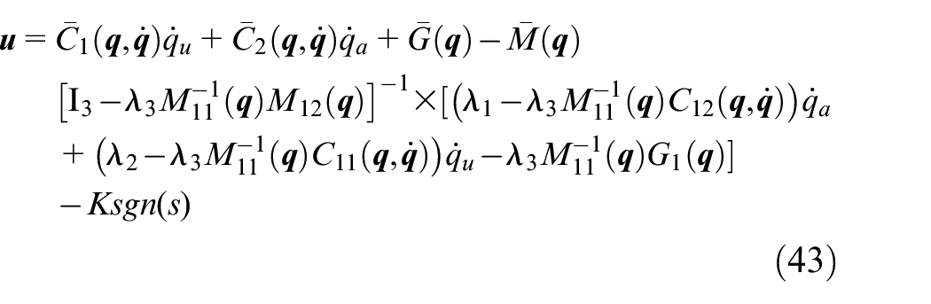
In (43), the matrix
Stability analysis
Since the controller of (43) ensures that all state variables can reach the sliding mode surface s = 0, the tracking trajectory has also reached the sliding mode surface s = 0. Then, when

which implies that

For the underactuated state, combined with (31), (32), and (43), when

where

Given the three state variables
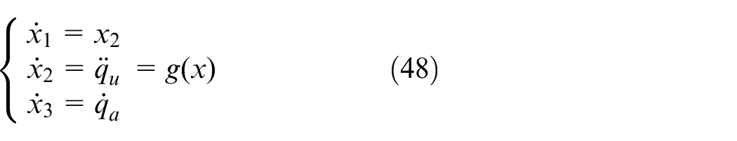
Substituting the state variable

If the acceleration function
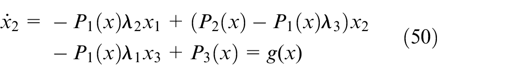
For the convenience of subsequent calculation, an expression
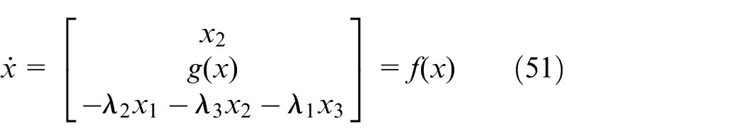
The expression (51) is an independent system, and the system can converge to zero asymptotically by choosing appropriate
Linearizing equation (51) near the equilibrium point of x = 0, the following linear system can be obtained

where
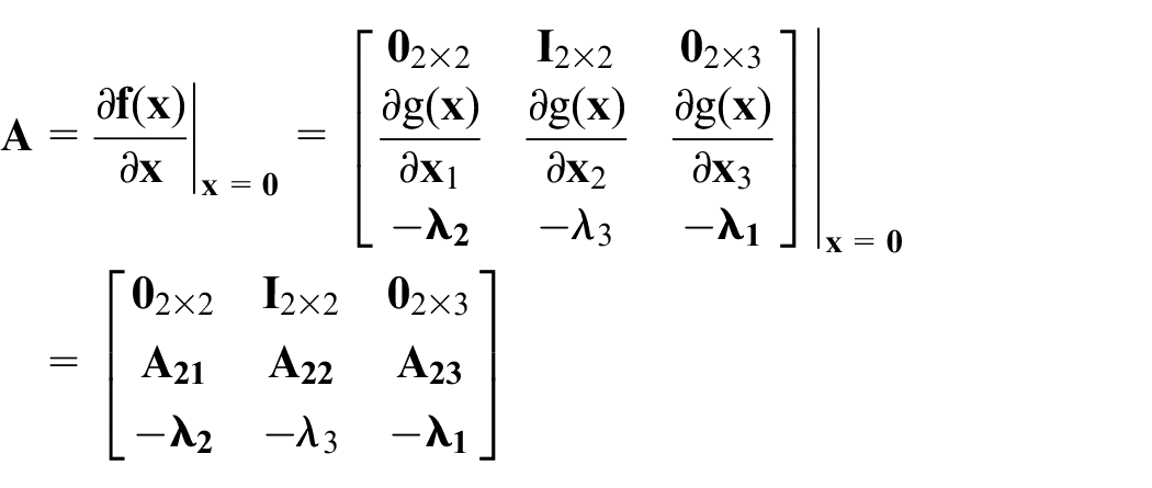
By calculation, the coefficient matrices
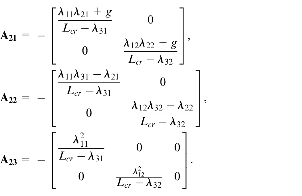
In order to ensure the stability of the linearized system given by (52), the linearized state matrix
According to the optimal control theory, if the form of a matrix E is:
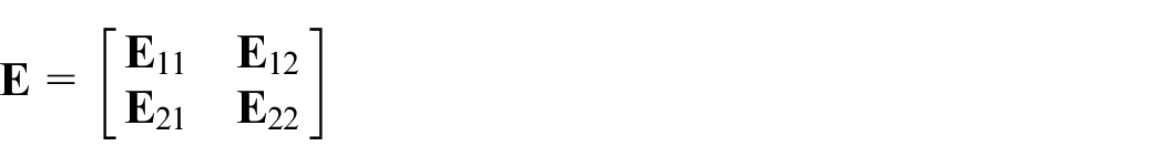
then the determinant of E,
where
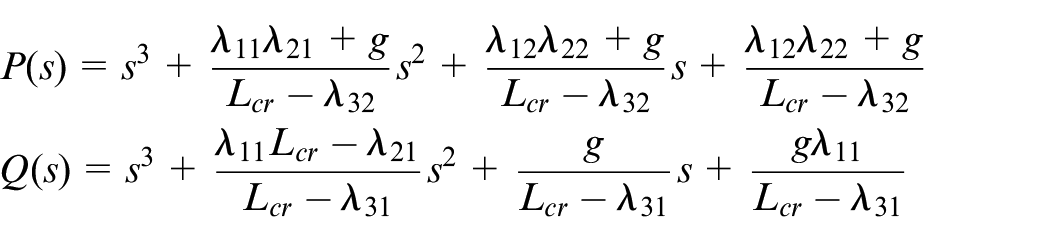
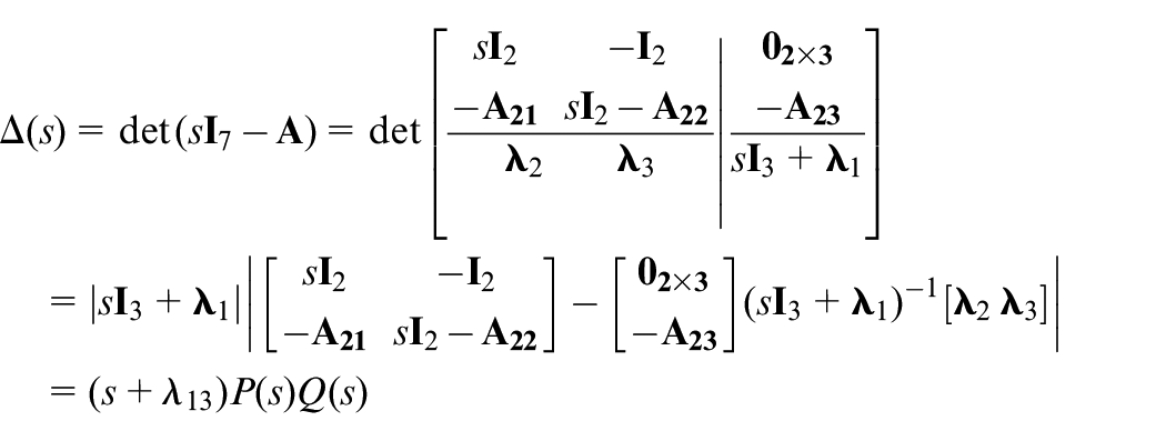
According to the hurwitz criterion, the necessary and sufficient condition for the stability of the linear system (52) is that the characteristic polynomials
The condition for the characteristic polynomial of the system (3.25) to be the hurwitz polynomials is:
It can be seen from (53) that the necessary and sufficient conditions for the stability of the sliding surface are determined by the parameters
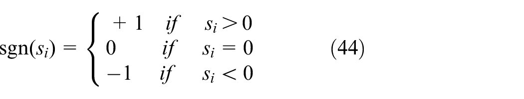
For the sake of formula concise, the saturation function is defined as
where, sign(s) is the sign function in (44),
Design of block disturbance observer
When the ship is subjected to waves rolling, pitching and heaving, it is equivalent to introducing an uncertain disturbance term

where,
The control system diagram of ship-mounted crane is shown in Figure 3. The proposed block disturbance observer availably compensates external disturbances due to ship rolling, pitching and heaving for ship-mounted crane systems, and the sliding mode controller drives the payload to the desired positions precisely and reduce vibrations.
Control system diagram of ship-mounted crane.
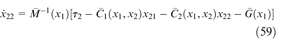
According to (29), (30), when the external disturbances exists, after separating the driving and underactuated components, the expression is rewritten as:

where,
Design of underactuated partial disturbance observer
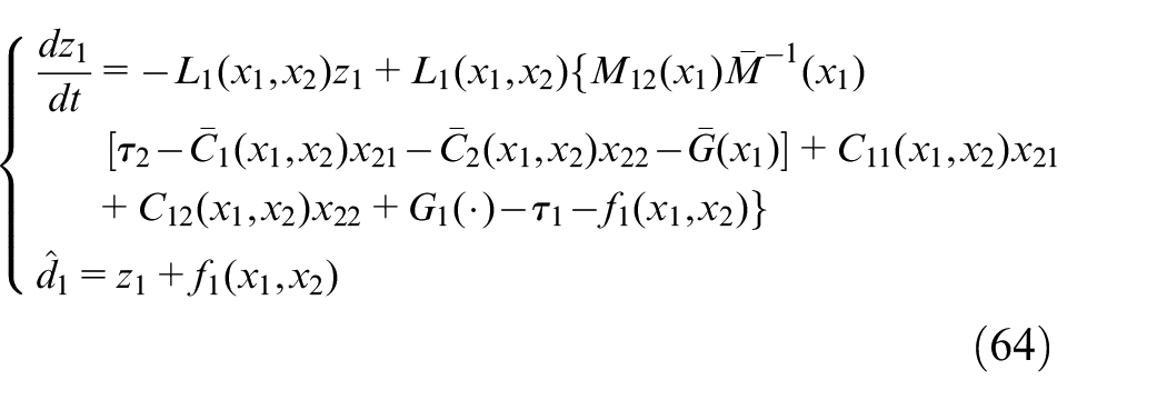
The disturbance in the underactuated state represented by (56) is estimated, and the designed disturbance observer is:
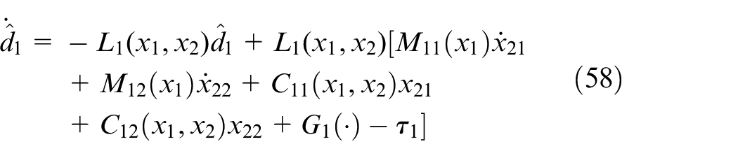
where,
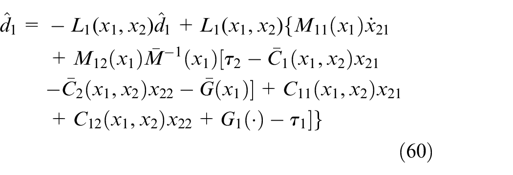
It can be seen from equation (58) that the designed disturbance observer contains not only the acceleration information of underactuated part
Substituting (59) into (58) yields:
The auxiliary function

where,
Let

Substituting (62) and (60) into (61) produces:
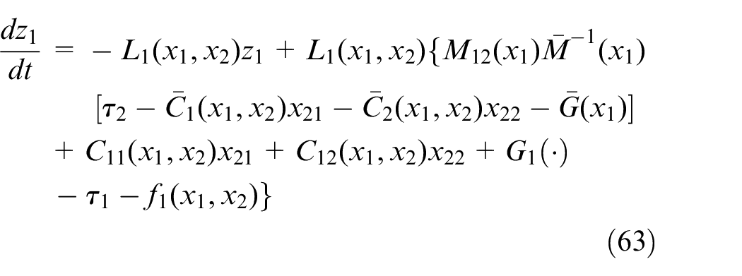
Therefore, the disturbance observer without acceleration information can be obtained as:
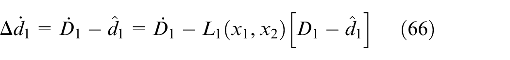
The estimation error of the disturbance observer is defined as:

In order to accurately estimate the external disturbance
When the disturbance is a slow time-varying signal that is
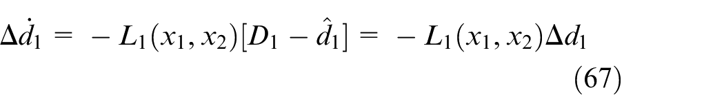
Let

where X is the undetermined gain matrix.
Substituting (68) into (62) and integrating both sides of (62) obtain:

The designed Lyapunov function is:

Since the inertia matrix
The derivative of (70) can be obtained (please refer to the Appendix for details)

In order to guarantee
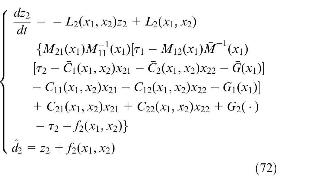
Design of disturbance observer for driving part
The design process of the disturbance observer in the driving part is similar to that in the underactuated part, and the proof process is omitted. The nonlinear disturbance observer is designed as follows:
Simulation and experiment
This section will verify the performance of the proposed approach by a series of simulation and hardware experiments.
Simulation results
For all the simulations, the system parameters are set as Mb = 5 kg, m = 1 kg, Lb = 1.25 m, Hc = 0.47 m, R1 =R2 = 0.015 m, J1 = J3 = 0.054 kg.cm2, J2 = 0.025 kg.cm2.
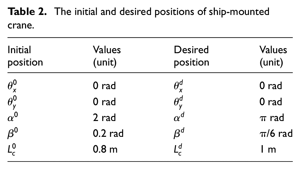
Without loss of generality, the initial and desired positions of ship-mounted crane system are shown in Table 2, and the initial velocities and accelerations are zero.
The initial and desired positions of ship-mounted crane.
When the ship-mounted crane works, it needs to be anchored and positioned, which limits the three degrees of freedom of sway, surge and yaw. Therefore, the hull is mainly affected by roll, pitch and heave of waves. In this paper, the three-level wind speed and sea state in China’s coastal area are taken as the research object to simulate the motion law of ships under such waves. According to the semi-empirical wave spectrum formula (73), which is recommended by the State Oceanic Administration of China, the wave spectrum is shown in Figure 4.
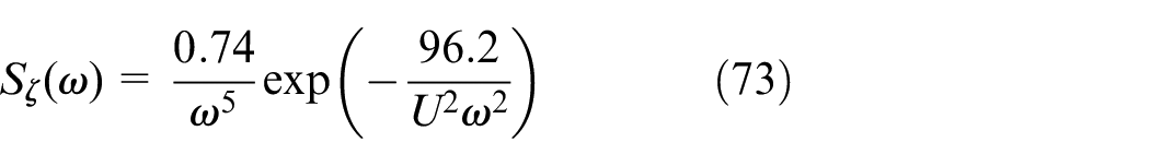
where ω is the wave frequency, and U is the wind speed.
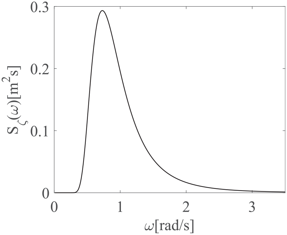
Wave spectrum.
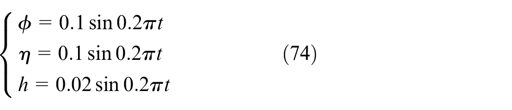
From the Figure 4, the main energy distribution of waves is [0.5,2], so the wave frequencies are set to 0.2 π rad/s in the simulation, the amplitude of roll and pitch is 0.1 rad, and the amplitude of heave is 0.02 m, that is,
For different working environments, two sets of simulation experiments are carried out, and compared with the ZV approach. 35 The first one, when the external disturbances do not exist, the traditional SMC method is used to control the ship-mounted crane. The second one, when the disturbances of (73) exist, the proposed CSMC method is adopted.
Taking the slew angle of the ship-mounted crane as an example, the ZV controller is shown in Figure 5, and the angular velocity and acceleration are 0.3 rad/s and 0.2 rad/s2 respectively.
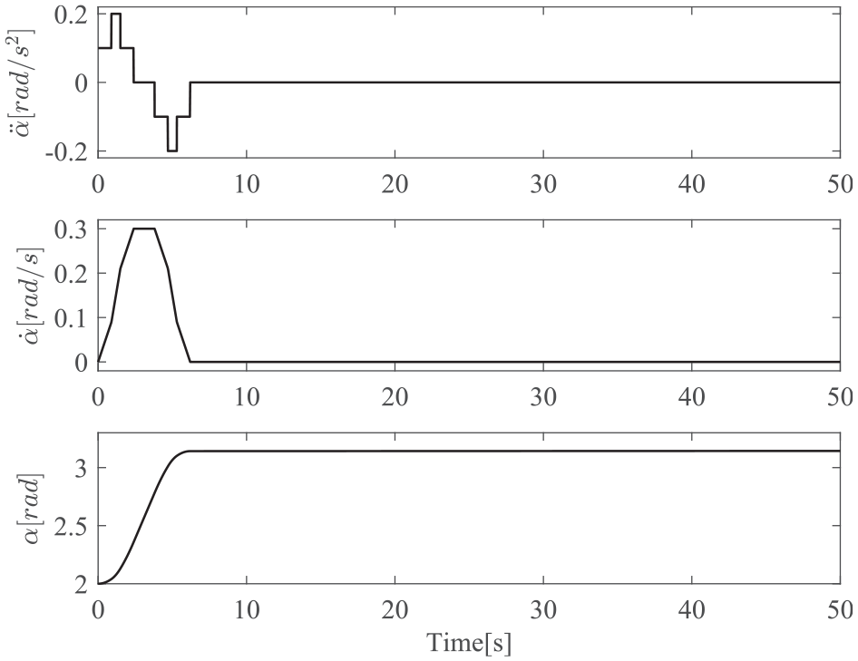
ZV controller.
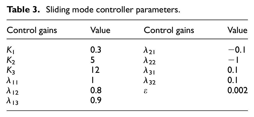
Selecting the initial parameters of the controller according to (52), and after careful tuning, the control gains of the proposed controller are shown as in Table 3.
Sliding mode controller parameters.
The first group simulation results without disturbances are shown in Figure 6. It is seen from Figure 6 that, the proposed SMC can effectively restrain the swing of the payload compared with ZV controller and uncontrolled, and drive the payload to the desired position within 10 s and no residual swing.
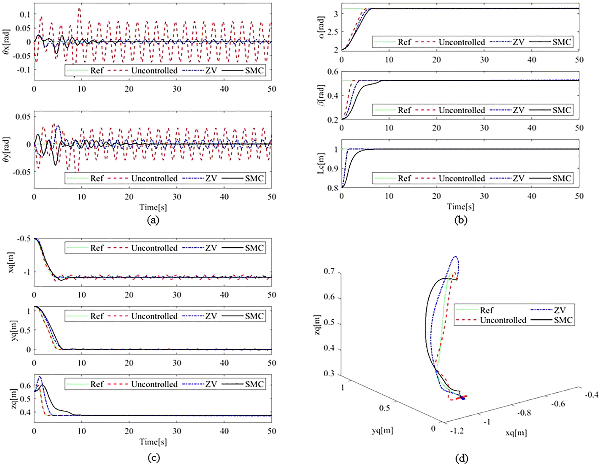
Simulation results without disturbances: (a) Swing angles of the payload, (b) Positions of the actuators, (c) Positions of the payload in the inertial coordinate, and (d) Three-dimensional trajectory of the payload.
The second group simulation results with disturbances are shown in Figure 7. It can be seen that, due to the disturbances of the sea waves, the payload has slight residual swing, but the amplitude is smaller compared with ZV controller and uncontrolled, indicating that the BDOB can address the external disturbances exerted by the sea waves. It is seen from Figure 7(b)that, the length of the payload rope has been adjusted periodically to counteract the wave heaving disturbance.
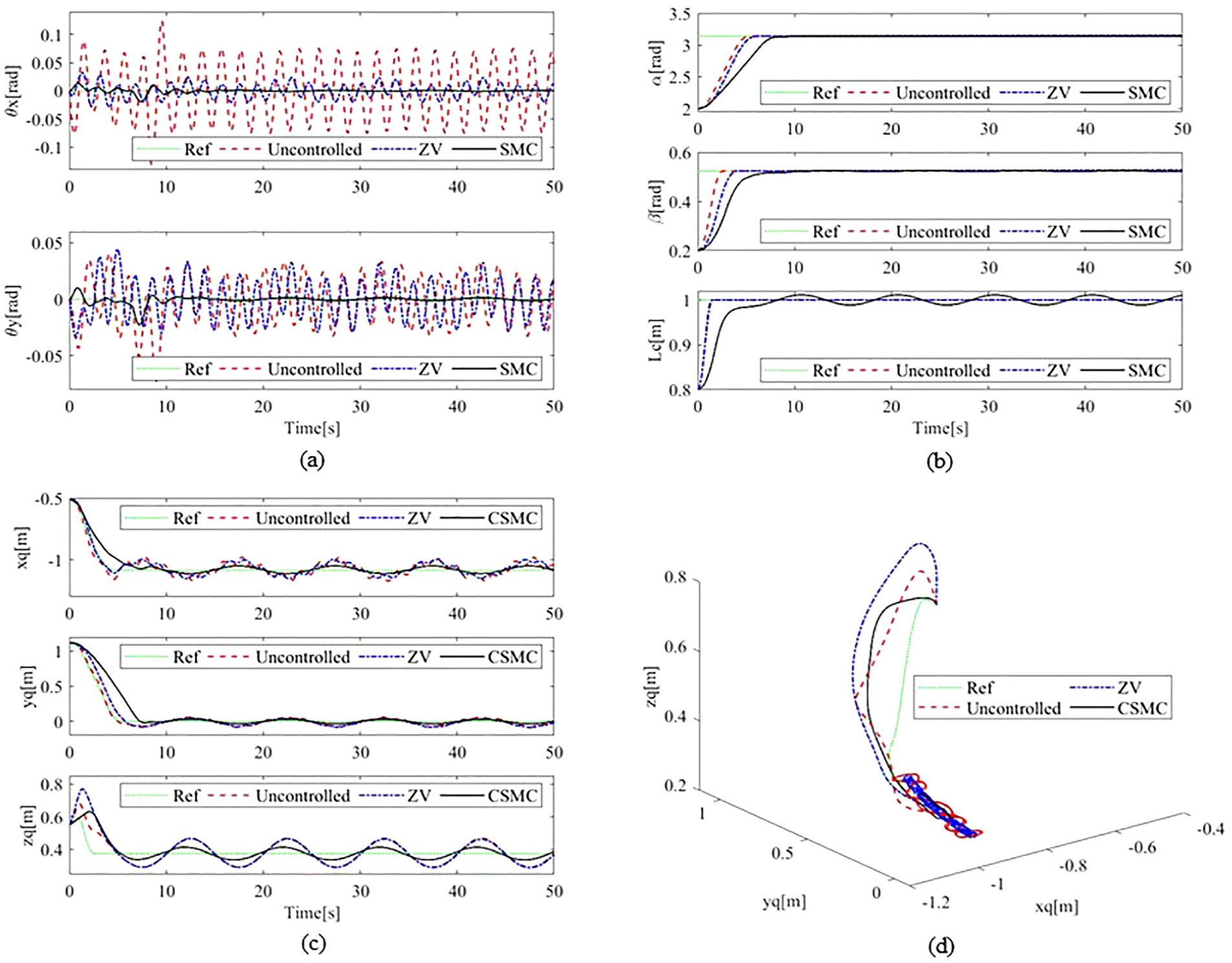
Simulation results with disturbances: (a) Swing angles of the payload, (b) Positions of the actuators, (c) Positions of the payload in the inertial coordinate, and (d) Three-dimensional trajectory of the payload.
Hardware experimental results
In this subsection, hardware experiments are implemented on a self-built ship-mounted crane platform, which is a boom crane, together with a wave generator by using the 3-RPS parallel mechanism as shown in Figure 8. The boom angles are detected by the encoders (220 PPR), and the sway angles of the payload are measured by a self-built angle sensor, which is composed of two incremental encoders (1000 PPR). A Googol GUS-600-TG02-HD six-axis Embedded Motion Controller is used to control the 3-RPS parallel mechanism to generate the waves and collects data from the sensors. The experiment model of ship-mounted crane is built in the MATLAB/Simulink environment.
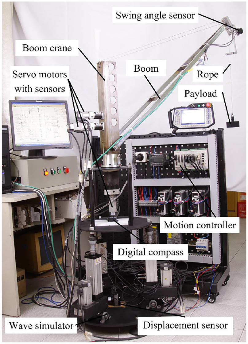
Self-built ship-mounted crane experiment platform.
To better verify the control performance of the proposed controller, two sets of experiment tests are carried out, and the experimental conditions are the same as the simulation.
Experiment 1
The first group experiment results without disturbances are shown in Figure 9. It is seen from Figure 9 that, the proposed SMC can effectively restrain the swing of the payload compared with ZV controller and uncontrolled, and drive the payload to the desired position quickly and almost no residual swing.
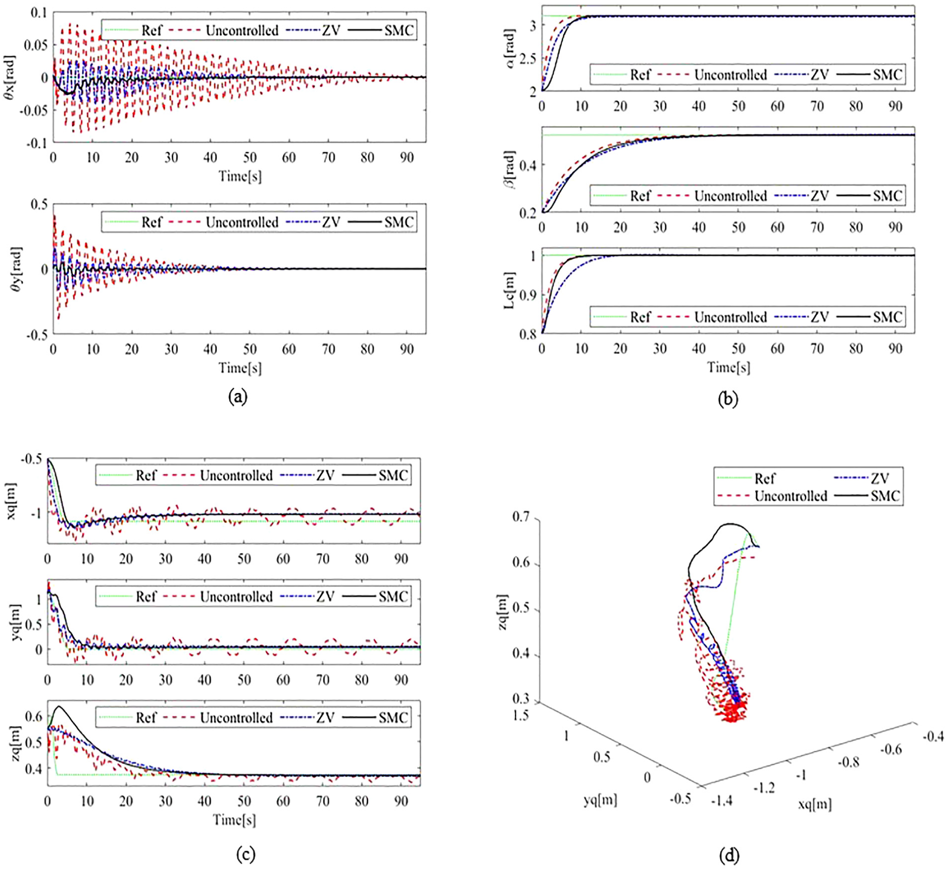
Experiment results without disturbances: (a) Swing angles of the payload, (b) Positions of the actuators, (c) Positions of the payload in the inertial coordinate, and (d) Three-dimensional trajectory of the payload.
Experiment 2
The second group experiment results with disturbances that are introduced by wave simulator, are shown in Figure 10. It is seen from Figure 10 that, the control process is more complicated due to the existence of external disturbances and the uncertainty of actual system parameters. However, it can be seen from the comparison experiment results that the proposed CSMC method shows better performance, which can effectively restrain the swing of the payload and with slight residual swing.
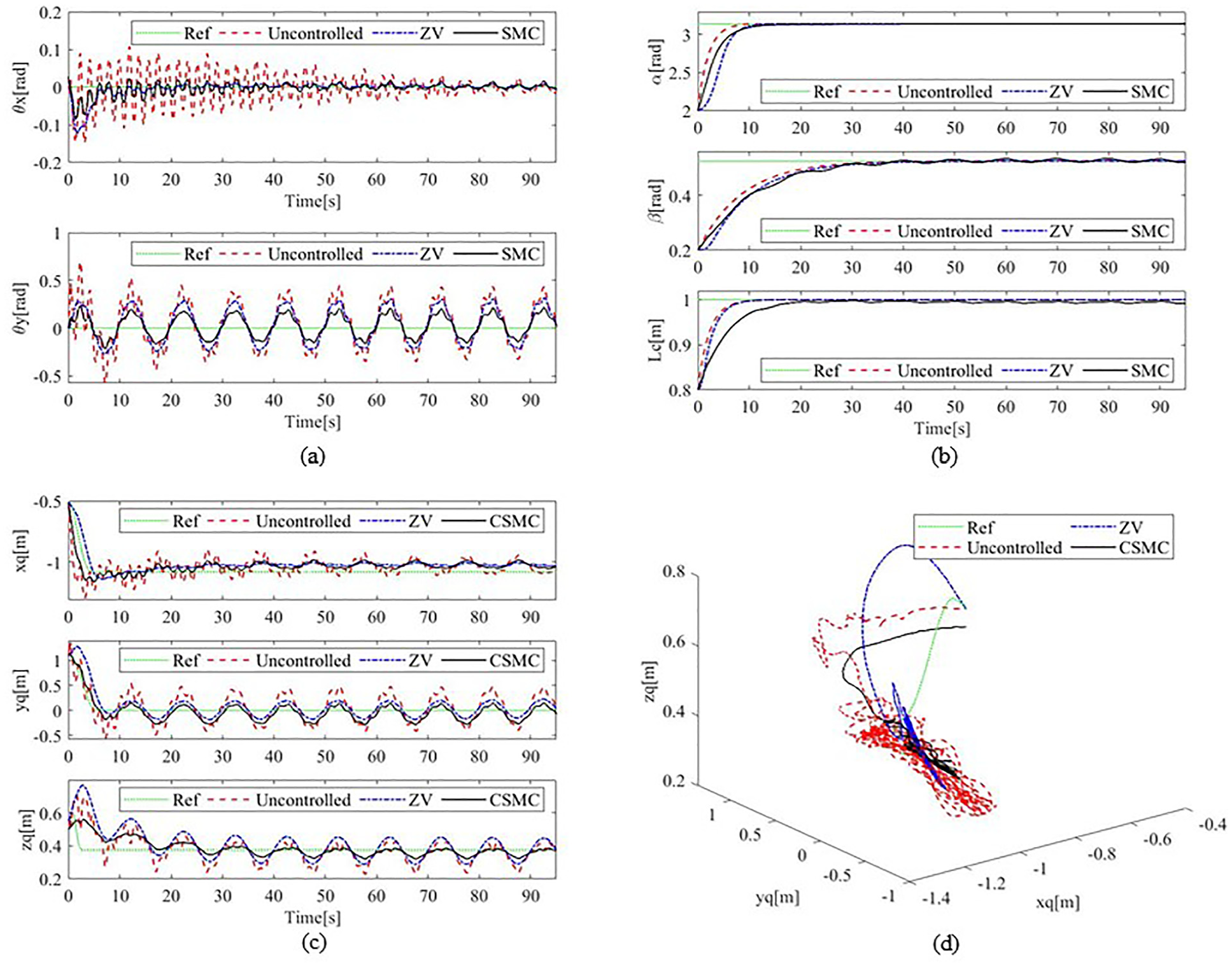
Experiment results with disturbances: (a) Swing angles of the payload, (b) Positions of the actuators, (c) Positions of the payload in the inertial coordinate, and (d) Three-dimensional trajectory of the payload.
To sum up, the proposed control method realizes the effective control of the ship-mounted crane and has strong robustness to different types of external disturbances.
Conclusions
In order to solve the payload swing of ship-mounted crane in the process of transportation, this paper proposes a block disturbance observer-based sliding mode control method. Firstly, the dynamic model of ship-mounted crane is established, and the sliding mode controller is designed by decoupling the original mathematical model. Secondly, a CSMC that combines block disturbance observer and sliding mode control is proposed, and the BDOB is used to address the external disturbances caused by the sea wave. Finally, a series of simulation and experimental are carried out, and the comparative experimental results show that the control performance of the proposed method is better than the traditional method, and produced a reduction of 93% in residual oscillations. In the future, in addition to studying the stability of proposed methods, the convergence of proposed methods should also be considered and compared with recently advanced methods.
Footnotes
Appendix
Detailed process for
Declaration of conflicting interests
The author(s) declared no potential conflicts of interest with respect to the research, authorship, and/or publication of this article.
Funding
The author(s) received no financial support for the research, authorship, and/or publication of this article.
Ethical Statement
Not applicable.
Informed consent/ Patient consent
Not applicable.
Trial registration number/date
Not applicable.
Data availability statement
Data sharing not applicable to this article as no datasets were generated or analyzed during the current study.