
Abstract
This article presents an experimental investigation into the damping characteristics of a linear damper with a newly designed oil groove. The damping performance of the damper is tested in four different viscosity grades by the sweep frequency method. And a test bench is used to move the damper for a several kilometers to examine the damping maintenance. The experimental results show that a higher oil viscosity leads to a higher damping capacity of the linear damper, and the increase in the oil viscosity will improve the damping maintenance of the damper. The newly designed oil groove efficiently improved the damping capacity of the linear damper; a proper oil selection will further optimize the effect of the oil groove via minimizing the oil leakage.
Introduction
In the conventional machine tools, hydrostatic guideways and slide guideways are widely used as bearing and guiding functions. Due to the advances of manufacture technologies and industrial design facilities, the linear guideways, with high position accuracy, load-carrying capacity, 1 reliability, and low coefficient of friction, have replaced the hydrostatic guideways and slide guideways in most mechanical systems. Besides all the advantages of the linear guideways, the low damping characteristic is inevitable as the contact between the rolling element and raceway is a point contact or a line contact at most.
Although different kinds of mechanical dampers, used at the interface of the sliding elements, that is, table, saddle, and bed, are designed to improve the damping characteristics of the linear guideways, 2 the heavy damper serves its purpose of damping the system as well as increasing its modal frequency; however, it still retains much of the low damping characteristics of the linear guide system. The damping performance of the linear guide is far from that of the slide guide in machine tools. 3
Many studies4,5 show that damping oil films, applied in the mechanical system, can achieve a better damping performance. Therefore, oil-film damping technology can be applied into the linear guideway. 6 Based on the oil-film damping technology, INA Co. 7 has developed a damping carriage, so-called RUDS, which only fit on the INA linear guideways to decrease the amplitude in full frequency range. Rahman et al. 3 used impregnated concrete, a new material instead of steel, in the damping carriage, and verified an improved damping capacity and dynamic characteristics of mechanical systems within the frequency range of up to 650 Hz.
Jacobs et al. 8 investigated the influence of the lubricant film on the damping characteristics of a deep groove ball bearing. Through experiments, they have found that the damping of bearing is reduced when the viscosity or the thickness of the lubricant film decreases.
Powałka and Okulik 9 reported a new technology for the assembly of ball guideway systems which involved the use of a thin layer of a casting compound. The experimentally verified simulation research, presented in the work, indicates that the use of the casting compound between the guide rail and the bed of the machine tool positively influences the dynamics of the system.
Chu and Holmes 10 designed a flexible shaft with an overhung disk supported by the squeeze-film damper to suppress the vibration of a rotating assembly. In the article, the new structure with squeeze-film was proved to lower the resonance peaks and the frequencies of the rotating assembly experimentally.
To improve the damping capacity of the linear guideway system using the linear damper, single damping carriage is woefully inadequate. As the oil film between the damping carriage and rail is a key element to increase the damping capacity, some units are applied into the system to maintain the oil film. As shown in Figure 1, the damping linear guideway system consists of a rail, two carriages, several copper caps, and a damping carriage. The copper caps are embedded in the bolt holes of the rail to smoothen the rail surface which will generate the oil film successfully on the rail surface. However, the carriages of the damping linear guideway system are installed on the working table of the machine tool and in reciprocating motion, oil leaking may occur, and the oil-film damping may fail.

Schematic of the damping linear guideway system.
A new design linear damper with an oil groove shown in Figure 2 was recently introduced by the current authors to maintain a constant oil film between the damping carriage and rail. This article investigates the damping performance of the linear damper with the newly designed oil groove (LDWG). The damping characteristics of the LDWG in different oil viscosities are examined. And according to the linear damping system, a vibration model is built which will explain the oil viscosity influences for the damping capacity. Additionally, to prove the improvement of damping maintenance of LDWG, the test bench is used to drive the dampers to move at the velocity of 300 mm/s under the load of 6000 N. However, the test also shows the oil viscosity may affect the damping maintenance to a certain degree.

The linear damper with oil groove.
Description of the linear damper with oil groove
The new damper is manufactured by HTPM, based on the available model of HTPM DS45R EA – 300. 11 As shown in Figure 2, the damper consists of the mild steel base with eight screwed holes, three oil holes, an oil groove and a shallow slot, as well as the turcite lining. The oil groove is above the three oil holes to store supernumerary oil and to supply the oil film when the oil-film leaking occurs. The shallow slot is designed to reduce the contact surface area of the linear system to make the damper carriage fit the rail well.
Experimental apparatus and method
Outline
To test the damping characteristic and damping maintenance of the damper, a new experimental system is built. The system is shown in Figure 3, which comprises a test bench, a loading mechanism, a vibration generation system, and a linear damping guideway system to be measured. The test bench is used to drive the linear damping carriage to move back and forth in a prescribed velocity. The load mechanism is used to provide the vertical load on the linear carriages. The vibration generation system is used to create the exciting force on the linear damping guideway system.

Schematic of the whole experimental system.
Loading mechanism
The loading mechanism consists of two main parts, part 1 and part 2, as shown in Figure 4. Part 1 is connected to the working table. And a trapezoidal screw, installed in part 1, is on top of the force sensor. Part 2, separated from part 1, consists of a planetary reducer which is used to rotate the trapezoidal screw. In the load applying process, part 2 is inserted into the top of part 1 and rotated by hands; then, the trapezoidal screw moves downward and transfers the load to the force sensor. The load from the force sensor is separated into two parts by the force-separate steel plate and applied on the joint plate connecting the linear carriages and the damping carriage.

Schematic of load mechanism.
Vibration generation system
Different from the impact transient testing through a hammer,3,9,12–14 the sweep frequency testing15,16 can provide a larger and constant excitation force. Here, the sweep frequency testing is applied in the experiment. The vibration generation system is composed of two parts, the mechanical part and the measurement-control part, as shown in Figure 5.

Apparatus and method of the vibration generation system.
In the mechanical part, four screws, connected to the frame, are used to adjust the distance between the vibration generator and the tested linear guideways. Four springs, used to isolate the vibration, are set between the screws and the vibration generator through the steel plates. The output head of the vibration generator is connected to the joint plate, and two accelerometers are also connected.
In the measurement-control part, the operation includes the following steps: (1) the signal generator sends the sinusoidal signal, at the frequency range of a prescribed value, to the power amplifier; (2) the power amplifier magnifies the sinusoidal signal and transfers the signal to the vibration generator; (3) the vibration generator excites the linear damping guideway system at the sinusoidal excitation force; (4) the response signal of the tested linear damping guideway system is collected by the accelerometers and transmitted to the Prosig P8020 data acquisitor; (5) the raw data are processed by the P8020 and sent to the laptop computer; and (6) the computer performs the fast Fourier transform (FFT) analysis with the acquisition software.
Damping performance
Some contrast experiments have been executed to investigate the different damping performances in different experiment conditions. The coordinate system of the vibration acquisition direction is shown in Figure 6, where the vibration model of the linear guideway system is built as well. According to the model, the vibration equation can be expressed as

where M is the mass of linear system; c1, c3 are the damping factors of linear carriages 1 and 2; c2 is the damping factor of damper; and k1, k3 are the rigidity factors of linear carriages 1 and 2.

Coordinate system and vibration model.
The vibration generator applied a sinusoidal force at the joint plate surface in the Z-direction. The excitation frequency is swept from 10 to 2000 Hz, while the amplitude is set at 3 Vpp. The excitation force can be expressed as

Laplace transforming the equation (1) yields

Substituting

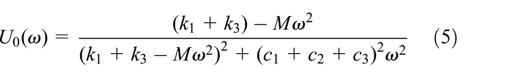

According to equation (4), the amplitude–frequency characteristic and the phase–frequency characteristic are expressed as
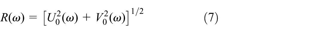
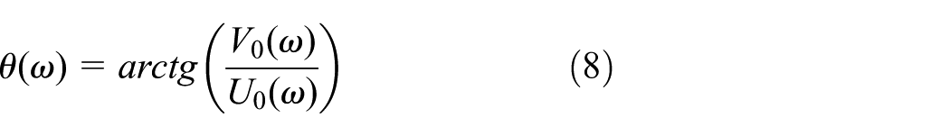
The response expression of the vibration system is

Substituting equations (5)–(8) into equation (9) yields
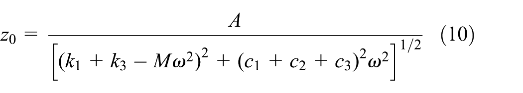
Substituting

We define the response amplitude–static displacement ratio as the dynamic amplification factor

where
According to equation (12), the peak values of the dynamic amplification factor under different damping ratios are shown in Figure 7. Clearly, the factor

The damping effect under different damping ratios.
As shown in Figure 8, the damping carriage DS45R and the LDWG are tested in both non-oiled condition. The damping factors can be regarded as the closed values. For the first modal frequency, the closed two peak values occurred. There are little differences in the vibration characteristic between the DS45R and LDWG which means that the oil groove changes the vibration characteristic of the damper not very obviously.

The vibration characteristic of the HTPM DS45R and LDWG.
Response of LDWG with the oil films of different viscosities
The LDWG is injected with four kinds of oil of different viscosities and excited by the vibration generator successively. The viscosity values of the applied oils are reported in Table 1. The measured results of the response–acceleration versus the frequency are depicted in Figure 9, and the first modal of the linear system is around 600 Hz, the second modal is around 1250 Hz, and the third modal is around 1850 Hz, which shows that the different oil viscosities do not affect the modal frequencies. Three main response peaks illustrate three main degrees of freedom (DOFs) in linear damper system. In the first modal area, shown in Figure 10, the response–acceleration of the LDWG with the oil films are lower than the non-oiled one. Clearly, the oil viscosity increases, the response–acceleration decreases, which means the increase in the viscosity can improve the damping capacity of the linear damping guideway system. Second modal represents the direction of Y or X. The response amplitudes for the second modal are affected by many other factors, for example, the yaw conditions in each test. And the peak values of the acceleration between 500 and 700 Hz are recorded and shown in Figure 11. The peak values versus oil viscosity curve at 40°C shows a lower decreasing rate for the higher viscosity range between 46 and 150 mm2/s than the lower viscosity range between 0 and 46 mm2/s. And the tendency is in good agreement with the theoretical results. In other words, the damping capacity seems to improve relatively slowly, when the viscosity is greater than 46 mm2/s. Oil viscosity values higher than 150 mm2/s were not tested as the effect on damping performance is expected to be insignificant according to Figures 7 and 11.
Oil viscosities at 40°C.


Response–acceleration of the LDWG.

Response–acceleration of the LDWG in the frequency range from 500 to 700 Hz.
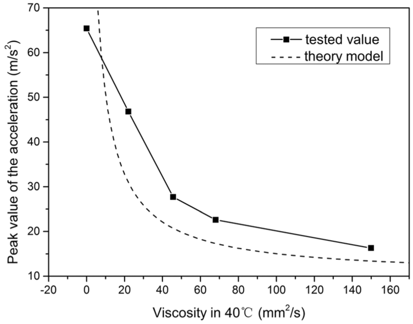
The peak value of the acceleration variation with the viscosity of the oil at 40°C.
The oil damping maintenance
Both the LDWG and DS45R are moved by the test bench at the velocity of 300 mm/s and under the load of 6000 N. Since this work was focused on the effect of oil viscosity, it is appropriate to use constant velocity and load in order to exclude their effect in the test results. Four kinds of oil of different viscosities are still used in two dampers. The linear damping system is tested by the vibration generation system in each 1000 m. And the peak values of the vibration amplitude in the time domain are recorded. The oil damping maintenance of the two dampers is shown in Figure 12. To the DS45R in four kinds of oil, the oil leakage happens in the first 1000 m. And to the LDWG, the oil leakage area of four kinds of oil is in the distance between 2000 and 9000 m. This result shows that the oil groove reduces the oil leakage in four viscosity types of oil.

The oil damping maintenance of the LDWG and DS45R.
According to the tested results of LDWG, shown in Figure 12, the oil leakage area of Mobil-No 10 is from 2000 to 3000 m. The area of L-HM46, Mobil-Vg68, and L-CKC150 are 4000–5000, 6000–7000, and 8000–9000 m, respectively. The oil maintenance distance versus viscosity is shown in Figure 13. It seems that the damping maintenance increases with the increase in the viscosity.

Oil maintenance distance versus viscosity.
Conclusion
The following conclusions are drawn from the experimental results:
The new damper with the oil groove exhibits little difference in vibration characteristics compared to the HTPM DS45R damper.
The oil films of different viscosities, although not affecting the modal frequencies, will damp the vibration modes of the linear guideway system. When the viscosity value is greater than 46 mm2/s, the gaining rate of damping capacity starts decreasing with the increase in viscosity. Therefore, it is unnecessary to choose the highest value of oil viscosity in order to achieve the best damping performance. An oil viscosity greater than or equal to 46 mm2/s is recommended, which would provide ideal damping performance according to the test results.
From the experiments of LDWG and DS45R, moved at the velocity of 300 mm/s under the load of 6000 N, it is verified that oil leaking, which affects the damping maintenance, does happen. And the damping maintenance performance of LDWG is better than DS45R in four kinds of oil of different viscosities. Additionally, the increase in oil viscosity will also improve the damping maintenance performance.
Footnotes
Acknowledgements
We wish to express our gratitude to Guangdong HTPM Co., Ltd, for providing the test linear guides and for helpful suggestions. We are also very grateful to the Key Laboratory of CNC Functional Components Performance Testing and Reliability of the China Machinery Industry for providing the test bench and measuring equipment.
Academic Editor: David R Salgado
Declaration of conflicting interests
The author(s) declared no potential conflicts of interest with respect to the research, authorship, and/or publication of this article.
Funding
The author(s) disclosed receipt of the following financial support for the research, authorship, and/or publication of this article: This study was supported by the Chinese National Science and Technology Major Projects (grant no. 2016ZX04004007).