
Abstract
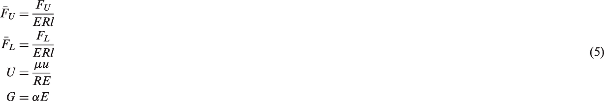
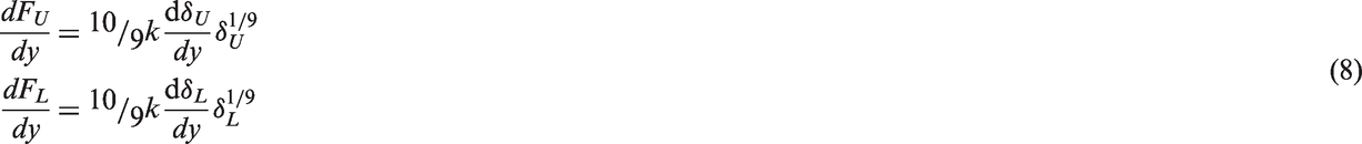
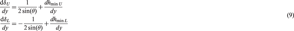
Linear guideways play a crucial role in determining precision of machine tools. Understanding their dynamic response is essential for objectively controlling their behavior and performance in operation. Due to highly loaded lubricated contacts, mixed-elastohydrodynamic regime is dominant. The mixed-elastohydrodynamic film maintains the coupling between horizontal degree of freedom (feed velocity) and vertical degree of freedom (loading direction). This paper presents a novel tribo-dynamic solution for linear guideways, taking in to account the lubricant effects and coupling between horizontal and vertical degrees of freedom. An analytical tribology model is used implicitly within the dynamic model. For in-depth tribological quantities including pressure and film thickness distribution, an explicit full numerical solution for mixed-elastohydrodynamic is utilized. Results show that the coupled solution of vertical and horizontal degrees of freedom taking in to account lubricated contacts is essential. It is shown that at moderate and light loads, the effect of this coupling and presence of lubricant is more pronounced.
Introduction
The Linear Guideway systems are widely used as an alternative for slip components for high precision machining applications. This is mainly due to low friction, high rigidity, and high precision.
Approximately 60% of the total dynamic stiffness and 90% of the total damping of the gantry machine tool comes from its joints, so the linear guideway contacts are key conjunctions, determining system’s dynamic and consequently its precision.1,2 The linear guideway simultaneously undergoes transverse and vertical motions. As a result, rollers in the linear guideway undergo complex movements such as slipping and mutual convergence (approach) or separation under oscillatory conditions. These movements are caused by changes in the applied load transmitted to the linear guideway, as well as the contact conditions between the rollers and the raceway grooves, 3 which results in instability of vibration,4–7 noise,8,9 fatigue10–12 and wear.13,14
On the other hand, the friction force affects the precision of the linear guideway by acting as a damping force, the frictional heat generation leading to the dynamic variation in stiffness and temperature deformation of the machine tool (thermal distortion). 15 Hence, due to the combined transverse and vertical motions, any predictions should be based on the combination of dynamic analysis and the consideration of tribological contact conditions.
Ohta and Tanaka 16 analyzed the contact characteristics and examined the vertical stiffness of preloaded linear guides, assuming both the rail and the carriage are flexible. Lynagh et al. 17 developed a model for studying ball bearing dynamic vibration and analyzed the effects of nonlinear contact condition on vibration characteristics based on the Hertz theory. The models neglected the effect of lubricant film on the system dynamics. Sarangi et al. 18 evaluated the stiffness and damping characteristics of isothermal, elastohydrodynamically lubricated point contact problems and considered the surface roughness effect and variation in viscosity with pressure. The purpose of this work was to obtain the coefficients of stiffness and damping of the roller bearings. Considering some assumptions, the pressure, oil film thickness, stiffness and damping coefficients are extracted using linear perturbation. Therefore, the actual dynamics and dynamic forces of contact are not specified. Wu et al. 19 analyzed the dynamic behaviors of linear guides by modeling the contact of ball to the rolling surface interface as a 3D membrane element. Kong et al. 6 studied the dynamic behaviors and stability of the linear guide considering contact actions. They derived the contact force according to Hertz contact theory and formulated a generalized time-varying and piecewise-nonlinear dynamic model of the linear guide to perform an accurate investigation on dynamic behaviors and stability. In this work, the effect of lubricant film was ignored. The studies mentioned above have assumed dry contact for rolling elements of linear guideway with Hertzian contact conditions and the oil effect was ignored. As already mentioned, frictional behavior is one of the important factors which affect the linear guideway dynamic characteristics. It is also important to determine the friction in order to predict
Kasai et al. 20 estimated the friction force in linear rotary type ball bearings guideway and concluded the total friction force at low speeds is equal to the sum of the friction forces related to the elastic hysteresis and differential slip. Tsuruta et al. 21 employed the same concept in modeling linear ball bearings guideway and presented a nonlinear model associated with the elastic deformation, Coulomb friction and Stribeck effect in the guideway. There are various other models representing the characteristics of friction in the linear guidway. Tanaka et al. 22 used the bristle model, Fujita et al. 23 employed the locomotive multi-bristle model, and Al-Bender et al. 24 suggested the Maxwell slip model to represent these characteristics. In all abovementioned studies, the oil effects are ignored. These models also do not predict the dynamical friction behaviors such as sliding and pre-sliding friction and frictional lag in the sliding and pre-sliding regimes for a lubricated roller guideway when the system operates under oscillating velocity condition.
Studies on the subject of the normal dynamic behavior of roller guideways have been conducted using the Hertz contact model while the lubricant effects are neglected25,26 and the coupling effect between vertical and horizontal directions is not considered.
As mentioned above, any model should include solution of lubricated rolling contacts within the linear guideways dynamic analysis. Incorporation of a full numerical solution of the lubricated contact in each step of the dynamic analysis is computationally time consuming, although possible. Therefore, the method used by Mohammadpour et al. 3 for roller bearings is followed in this work for linear guideways. This model used an analytical tribological model based on extrapolated oil film formula, incorporated implicitly in the dynamic solution. The squeeze velocity (lubricant viscous friction) within the oil film equation is obtained from the dynamic solution implicitly.
Although the implicit analytical tribology model is capable of accurately predicting film thickness, it cannot predict the film and pressure distributions of elastohydrodynamic contacts and asperity pressures in the mixed lubrication regime. In order to obtain these distributions, an initial dynamic analysis, coupled with implicit analytical tribology model can be enhanced by a full numerical explicit elastohydrodynamic solution. With contact load of the lubricated roller contact obtained from implicit dynamic analysis of linear guideway, an explicit elastohydrodynamic analysis can be performed that provides all the necessary tribological contact conditions, including combined sliding motion, mutual approach and squeeze effect.
This paper presents a new tribo-dynamic model for linear guideways that considers the coupling effect of transverse and vertical motions. The developed dynamic model uses the implicit tribological method described by Mohammadpour et al. 3 for the lubricated contact dynamics, in which an extrapolated oil film equation is used for line contact predictions. After calculating the load and contacts kinematics for each roller contact through this implicit tribo-dynamic analysis, a full numerical mixed-elastohydrodynamic analysis of a roller under oscillatory conditions and is utilized to obtain detailed tribological parameters. Such a comprehensive tribo-dynamic analysis for linear guideways, coupling transverse and vertical motions has not been reported in the literature hitherto.
Linear roller guideway dynamics
Each roller in the linear roller guideway contributes to the total applied load. Therefore, under dynamic conditions, the contribution of each roller varies. This means that determining the contact load of each roller using a quasi-static analysis is unrealistic. The oscillating nature of the contact in the linear guideway due to the machining and feeding dynamics results in the rollers being exposed to oscillating horizontal and vertical motions. The latter contributes to the squeeze film motion from tribological point of view.
As shown in Figure 1, the linear guideway includes rails, carriage and rollers that are in contact with them.
Schematic of recirculating linear roller bearing guideway.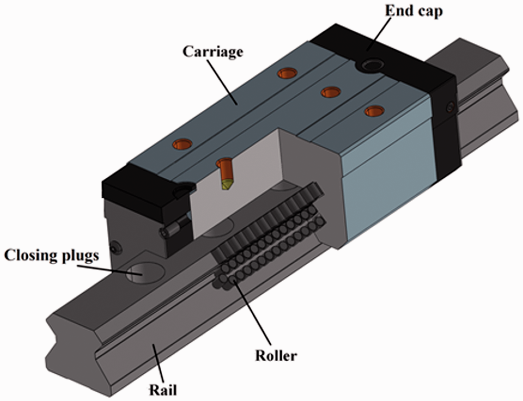
In this paper, for the dynamic analysis of a linear guideway, it is assumed that (1) the rail and carriage are rigid, (2) there is no side leakage in the EHL contact and (3) 3D edge effects including stress concentration and edge deformations are negligible and (4) the manufacturing errors, thermal expansions and imperfections can be neglected.
A two degree-of-freedom linear guideway system shown in Figure 2 is subjected to vertical force F and horizontal oscillation velocity. In the cutting process, the force Fand horizontal oscillation velocity represent cutting force and feed velocity. The linear guideway has four grooves annotated as 1, 2, 3 and 4.
Loads of the linear guideway system.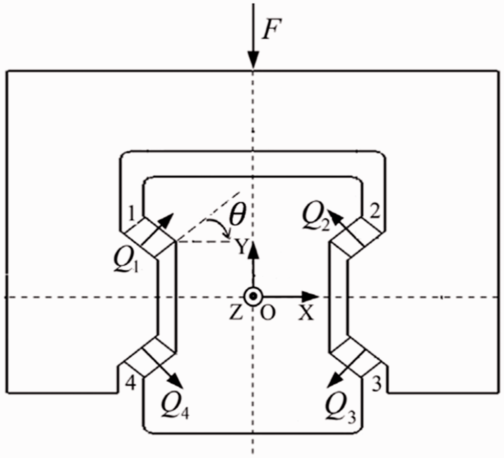
The normal force on each roller of groove i is Qi(i = 1,2,3,4). The initial deformation of the rollers in each groove is
The horizontal degree of freedom is considered to be kinematically constraint with the feed velocity. Equation (1a) is the feed velocity considered. Constant values in equation (1a) are obtained from an experimental rig which is outlined in the Experimental rig section. Hence, the linear guideway equations of motion can be reduced to one vertical degree of freedom under oscillating horizontal velocity as shown in equation (1b).


Unlike a circular roller bearing which applies variable load at different circular positions and hence different rollers, in the linear guideway all rollers are subject to equal load. They are also designed to ensure constant number of rollers in contact at all times which is not the case for roller bearings with variable loaded region. Hence, the number of rollers in contact is constant and the load is share equally which is the base of the current formulation. This is inline with the current literature investigating the normal dynamics of the linear guideway6,7 as well as those investigating friction and horizontal motion 27 which all neglect the localized dynamics of rollers. In practice, there could be some effects from rollers due to localized dynamics such as in the event of defect on the rail which is not considered in the current study.
In the equation of motion, N is number of rollers in each groove and M is mass of rail. FU and FL are contact forces of each roller in upper and lower grooves of linear roller guideway. The coupling between degrees of freedom is maintained via feed velocity, contributing to the film thickness and consequently FU and FL. Fe is the external force, which in dynamic analysis can include zero, constant values or harmonic behavior.
This contact force can be obtained from the load and deformation relationship modeled by Sun et al.
5
The contact deformation is considered as an elastic deformation between a finite length and elastic cylinder and a rigid plate. This is a realistic assumption under the conditions of elastohydrodynamic contacts.

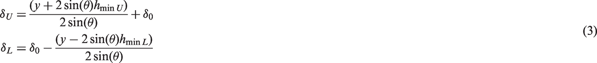
For line contact, the minimum film thickness in the upper and lower grooves can be expressed as
3
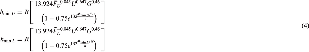
The dimensionless parameters
Quasi-static stiffness for linear guideway considering EHL conditions
It is beneficial to calculate the stiffness of the system in order to make interpretations of results. It will also help to understand the effect of EHL film on stiffness. In this section, the quasi-static calculations are undertaken for a series of deformation values considering EHL film thickness. The velocity values used for calculation of EHL film thickness are obtained from a representative steady-state cycle. The effect of squeeze velocity is also neglected. The relationship between the external normal force and the contact forces is as follows

The stiffness of linear guideway

By placing equation (9) in equation (8), we get


The quasi-static linear guideway’s normal stiffness in terms of vertical displacement is shown in Figure 3. The stiffness–normal displacement curve obtained in this paper is in line with the results of literature.5,6 As the load and vertical displacement increase, the contact forces in the upper grooves Stiffness vs. displacement in linear guideway considering EHL contacts.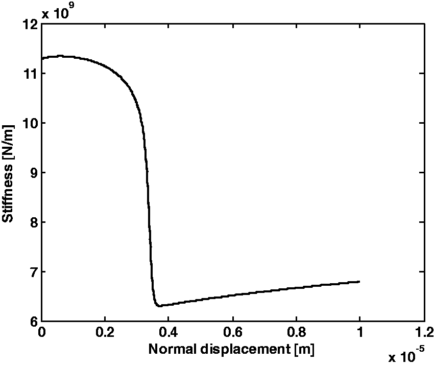
Quasi-static stiffness for linear guideway considering dry conditions
Under dry conditions,

The linear guideway normal quasi-static stiffness under dry conditions is shown in Figure 4.
Stiffness vs. displacement in linear guideway considering dry contacts.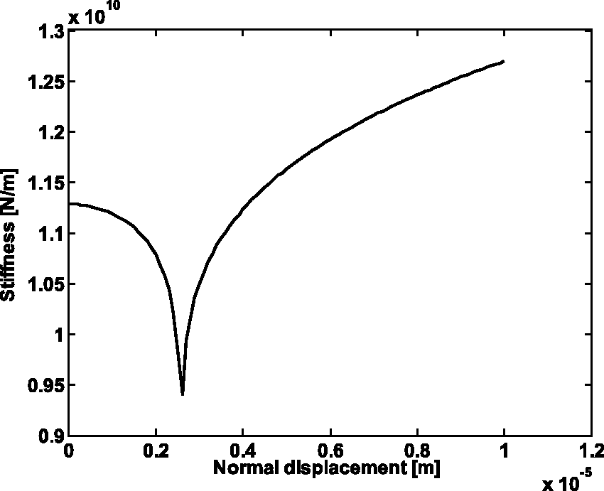
EHL contact model
To determine the film thickness and pressure distribution as well as friction force, a numerical EHL contact solution is required in the mixed lubrication regime. By changing the contact load determined in the previous section and the sliding velocity of the roller contact, the solution for a roller is obtained during a steady-state cycle of horizontal velocity.
The hydrodynamic pressure distribution and the film thickness in EHL contact are obtained by solution of Reynolds and load equations, considering the surface deformations. In mixed lubrication regime, the load in rough EHL contact is shared between the hydrodynamic film and asperities. As a result, roughness changes the load equation. Therefore, it is necessary to satisfy the asperity equation which relates the asperity pressure to the film thickness. At any point of contact due to the load sharing between the lubricant and the asperities, the total pressure is the sum of the hydrodynamic and asperity pressures
Schematic representation of EHL contact in mixed lubrication regime.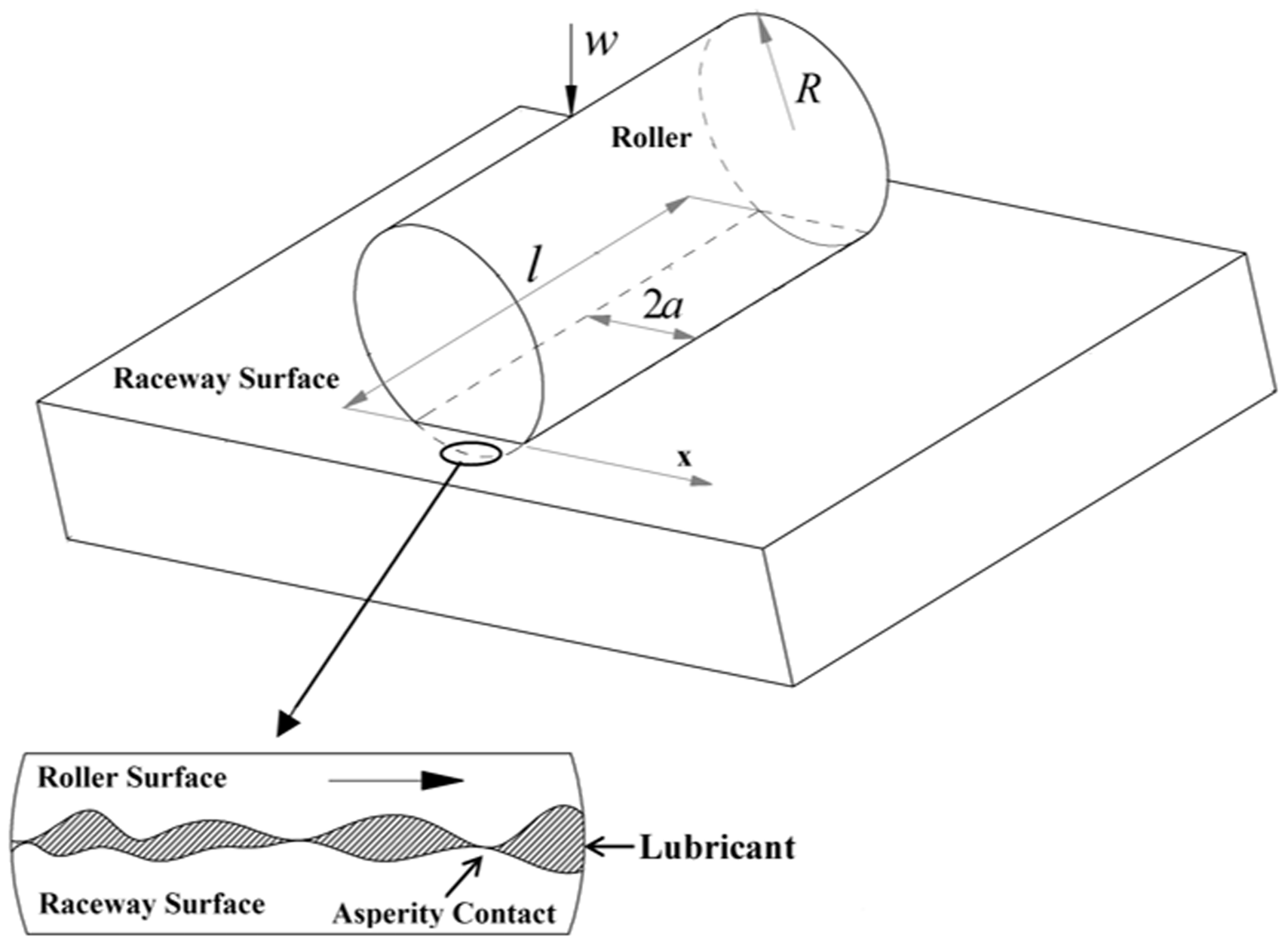

Greenwood and Tripp model
28
can be used to obtain surface asperity contact pressure. The method assumes Gaussian distribution of asperities. The share of contact pressure carried by the asperities is


Hydrodynamic pressure of the contact is obtained via solution of Reynolds equation. Below is the form of Reynolds equation used in this study which assumes thin film of Newtonian lubricant in a line contact
31

In equation (18), both viscosity

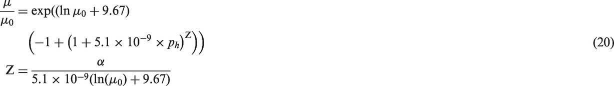
For the dependency of pressure-viscosity, Roelands equation
33
which is valid to use at moderate pressures is employed
In the modelling of EHL contact, the effect of temperature on viscosity and density is neglected. Also, the manufacturing errors, thermal expansions and imperfections are assumed to be negligible.
The Reynolds boundary conditions is assumed for equation (18) as

In equation (21),


Equations (1) to (3) are solved simultaneously, using the ODE45 solver in the Matlab. The results provide the contact load required for the mixed-elastohydrodynamic analysis. Then equations (16) to (23) are discretized using the finite difference method and Newton-Raphson method is also utilized for solving this system of equations simultaneously which includes EHL line contact and asperity contact forces. As a result, pressure distribution and film thickness are obtained.
Determination of friction
Greenwood and Tripp28 model is employed for prediction of boundary friction contribution. A proportion of load is carried by the asperities when mixed or boundary regimes of lubrication are encountered. The share of contact load carried by the asperities is
28

The asperity contact area is obtained as
28

The statistical function

Boundary friction can be presented as
34


Hydrodynamic friction (viscous shear) is obtained as

Viscous friction can then be calculated as

Therefore, the total friction force becomes

Experimental rig
In order to validate the presented model of lubricated roller guideways at system level, an experimental rig is developed. The same rig is also used to obtain the horizontal velocity excitation used in equation (1a). Figure 6 shows the experimental set-up consisting of a linear roller guideway system (INA RUE45-E
35
). In the set-up the carriage was fixed, while the rail was driven by a shaker. A force transducer B&K 8200 was placed between stinger and the structure to measure the driving force. The structure horizontal motion was measured using an accelerometer of type DJB A/120/V mounted at the tip of rail. Single harmonic excitation forces at low frequencies were applied to the rail. The force and response signals were measured and transferred to the data acquisition (DAQ) system. The force and response signals were measured with the sampling rate of 1600 Hz.
The experimental set-up.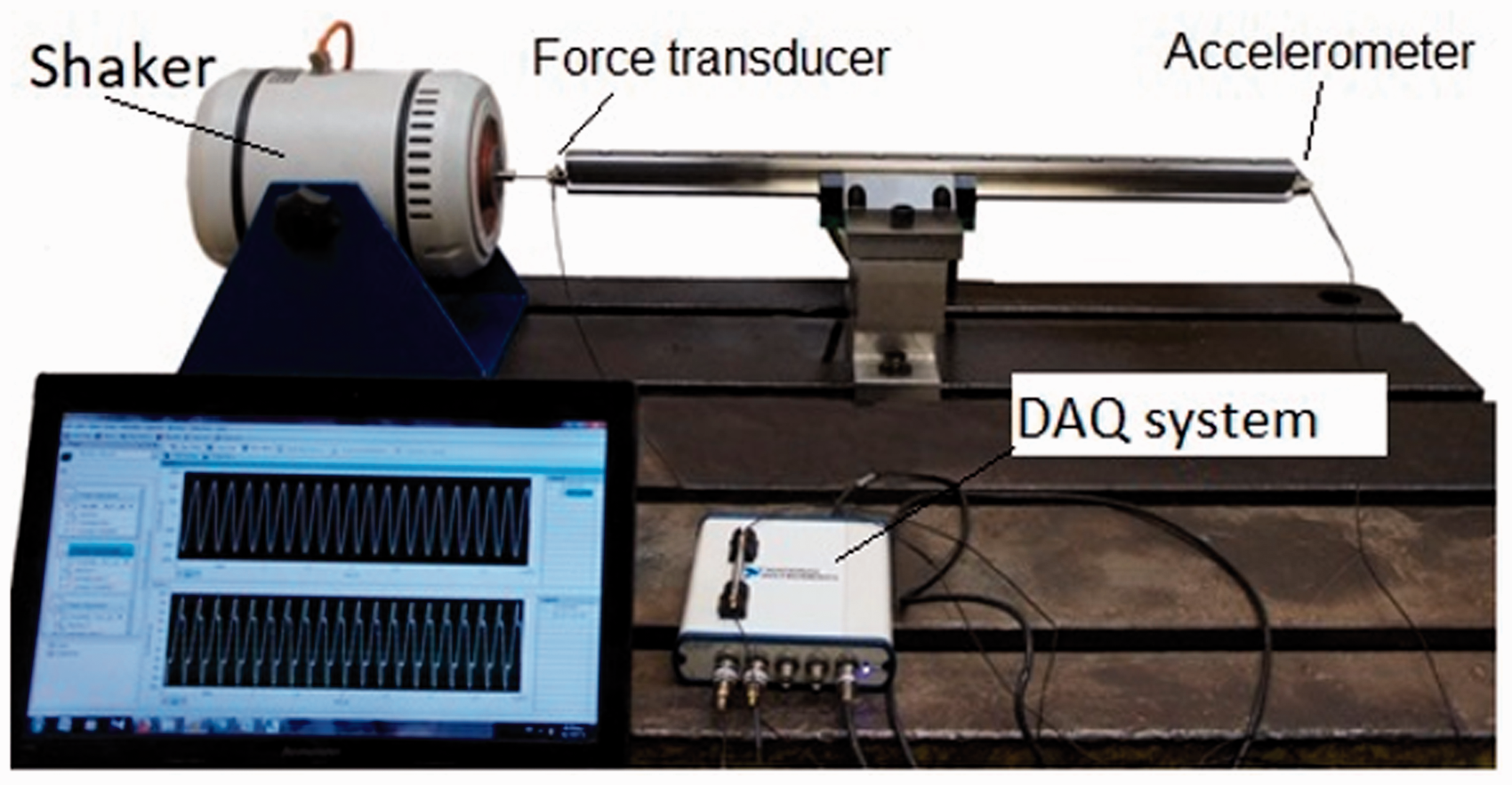
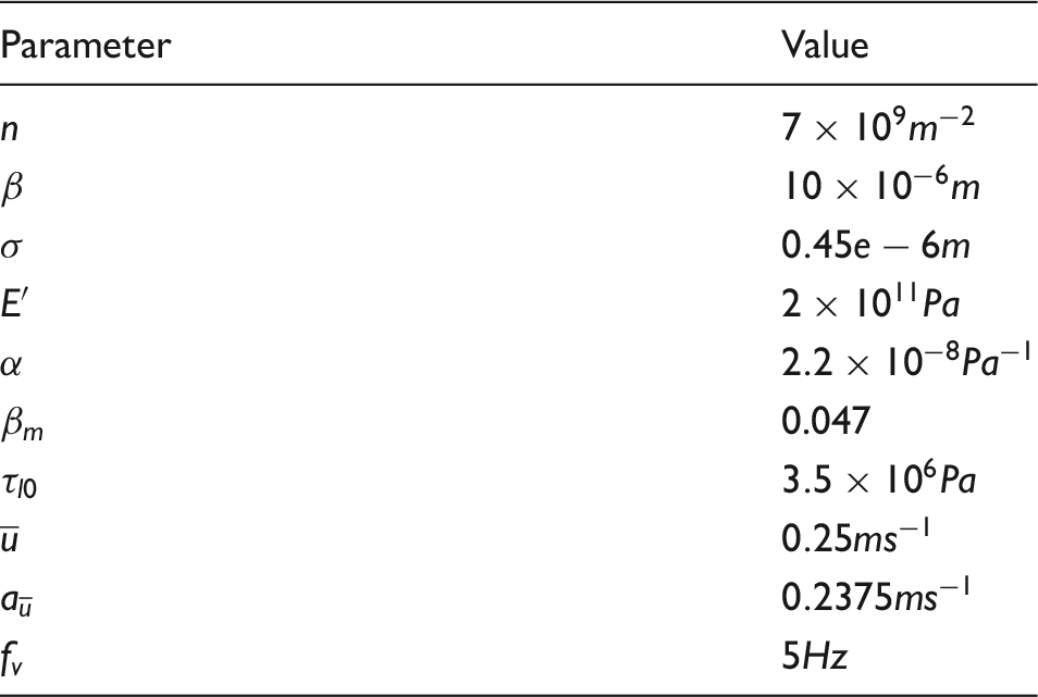
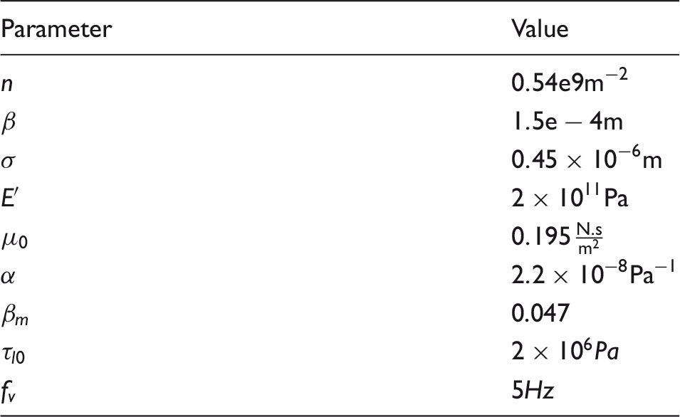
Input parameters of friction model and surface properties.
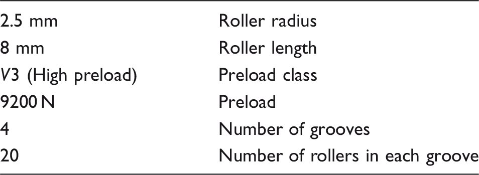
Guideway and roller specifications.
The contact friction force, Ff, was extracted as
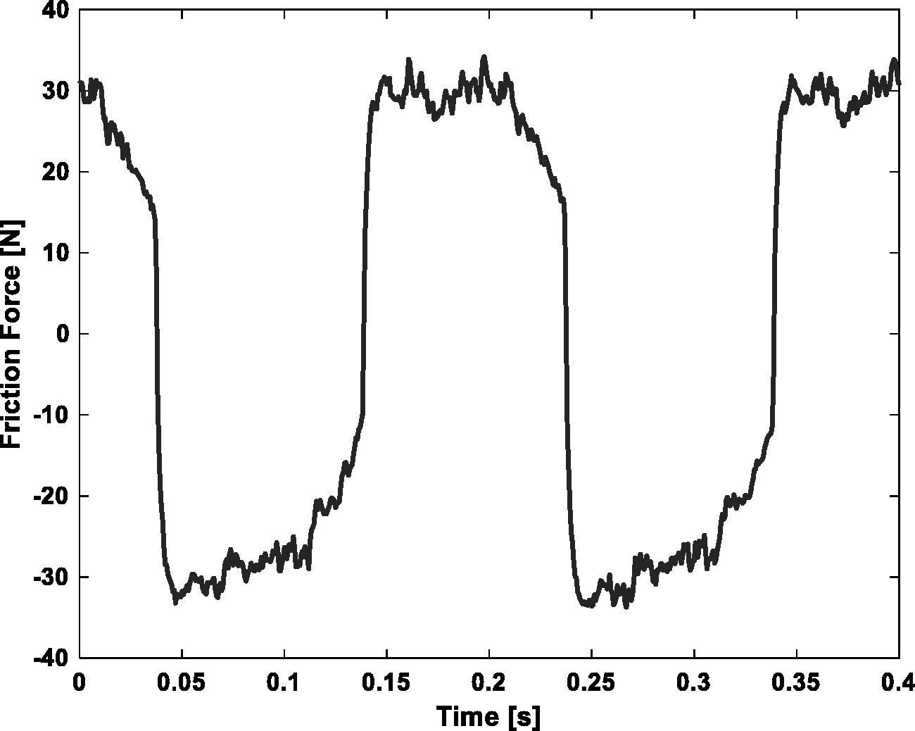
Measured friction force vs. time and at excitation frequency of 5 Hz.
The rail horizontal velocity is obtained by performing time integrations of measured acceleration. A Fourier series with two harmonics, first and third multiples of excitation frequency is fitted to the measured velocity signal for equation (1a), where Sliding velocity vs. time at excitation frequency of 5Hz; Measured (solid line) and fitted response (dash line).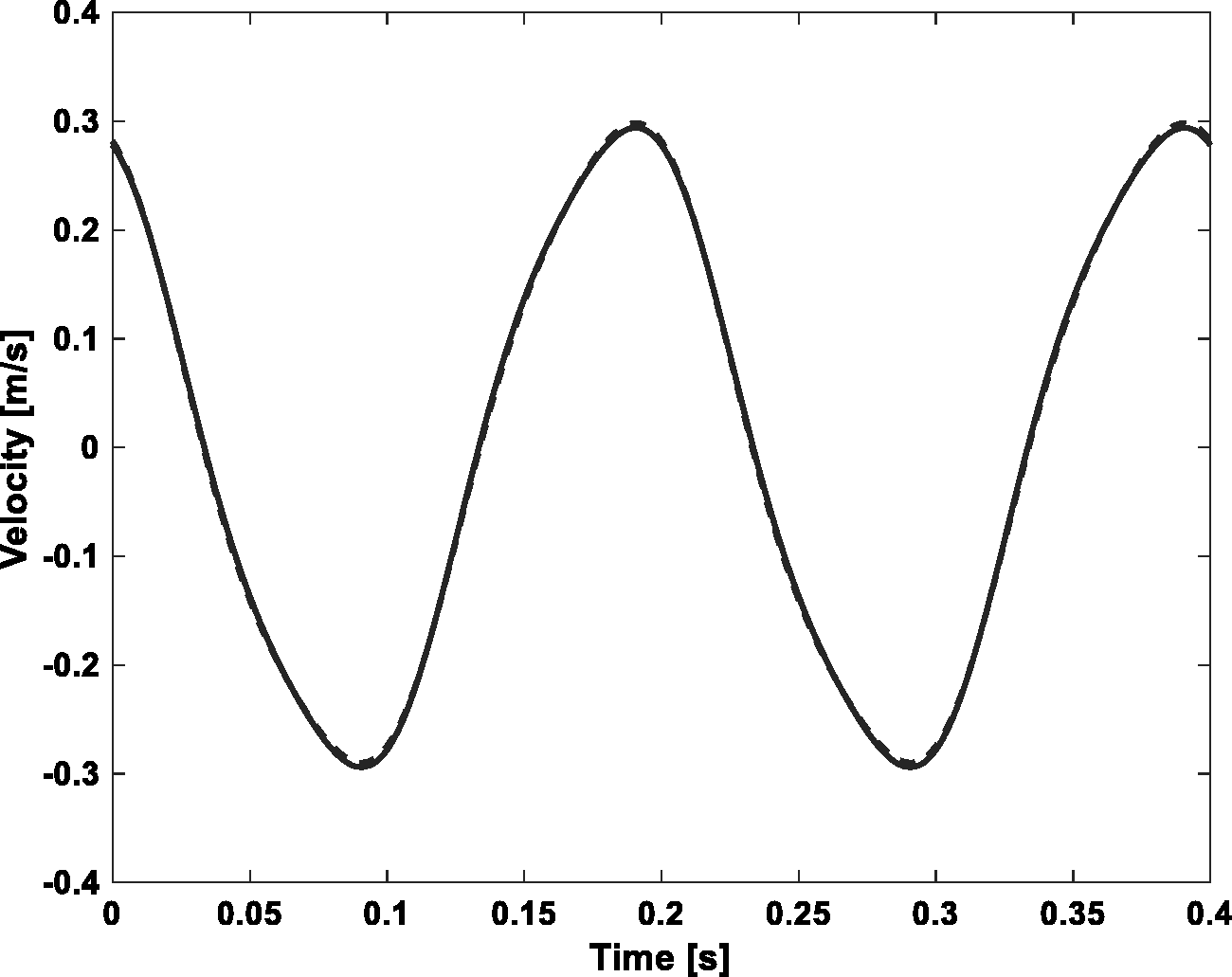
Results and discussions
Validation
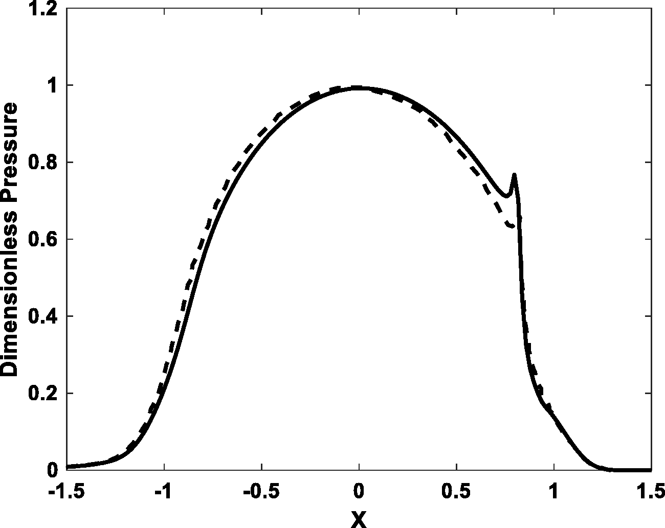
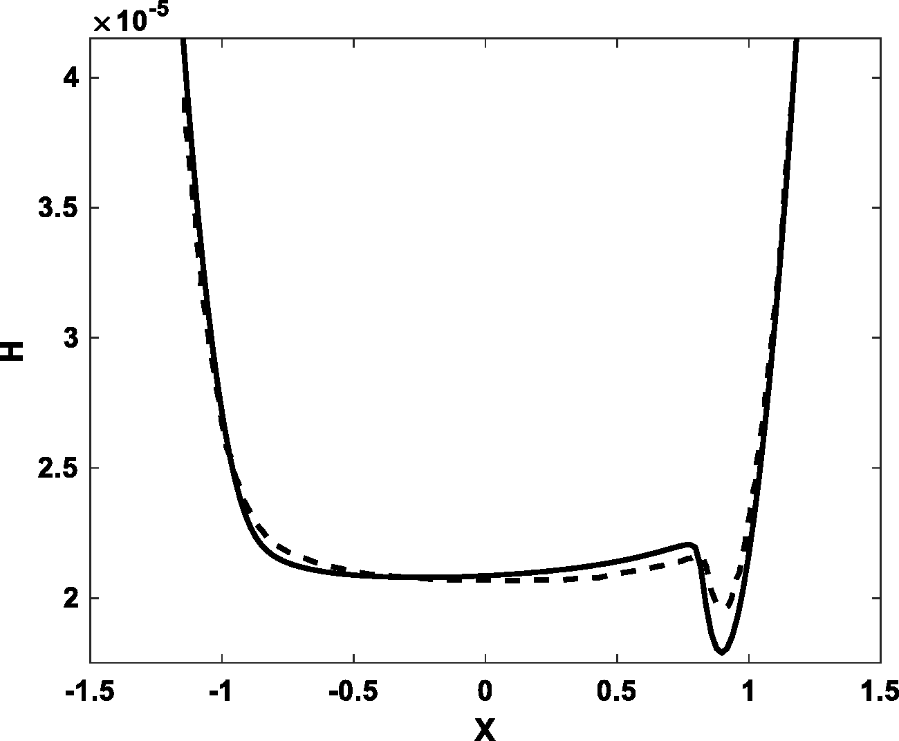
To validate the method presented in this paper, first the EHL film thickness and pressure distribution of the presented model are compared to the results of Masjedi and Khonsari
36
to provide conjunction level validation. Figures 9 and 10 show this comparison at W = 1 × 10⁻⁴, U = 1 × 10⁻¹¹ and G = 4500. As shown, the results of the present study are in close agreement with those reported by Masjedi and Khonsari.
36
Validation of pressure distribution, present model (solid), Masjedi and Khonsari (dash).
36
Validation of film thickness distribution, present model (solid), Masjedi and Khonsari (dash).
36
In practical applications and under machining conditions, the normal and horizontal dynamics of linear guideways are coupled. So, the direct and meaningful methods of validation of the normal dynamics model presented in this study are to derive the horizontal friction force as its output and compare with the experimental measurement. This will provide the system level validation. The velocity oscillations with nominal speed 
The friction is then calculated using the formulation presented in the Determination of friction section and equation (31) in which the normal and numerical EHL outputs including oil film were used and the results were compared to the experimental results of Hess and Soom.
37
The comparison is shown in Figure 11. Input parameters of friction model are presented in Table 1. As shown, the results of the present study are also in close agreement with this system level experimental measurement.
Comparison of friction coefficient versus velocity at w = 250 N and 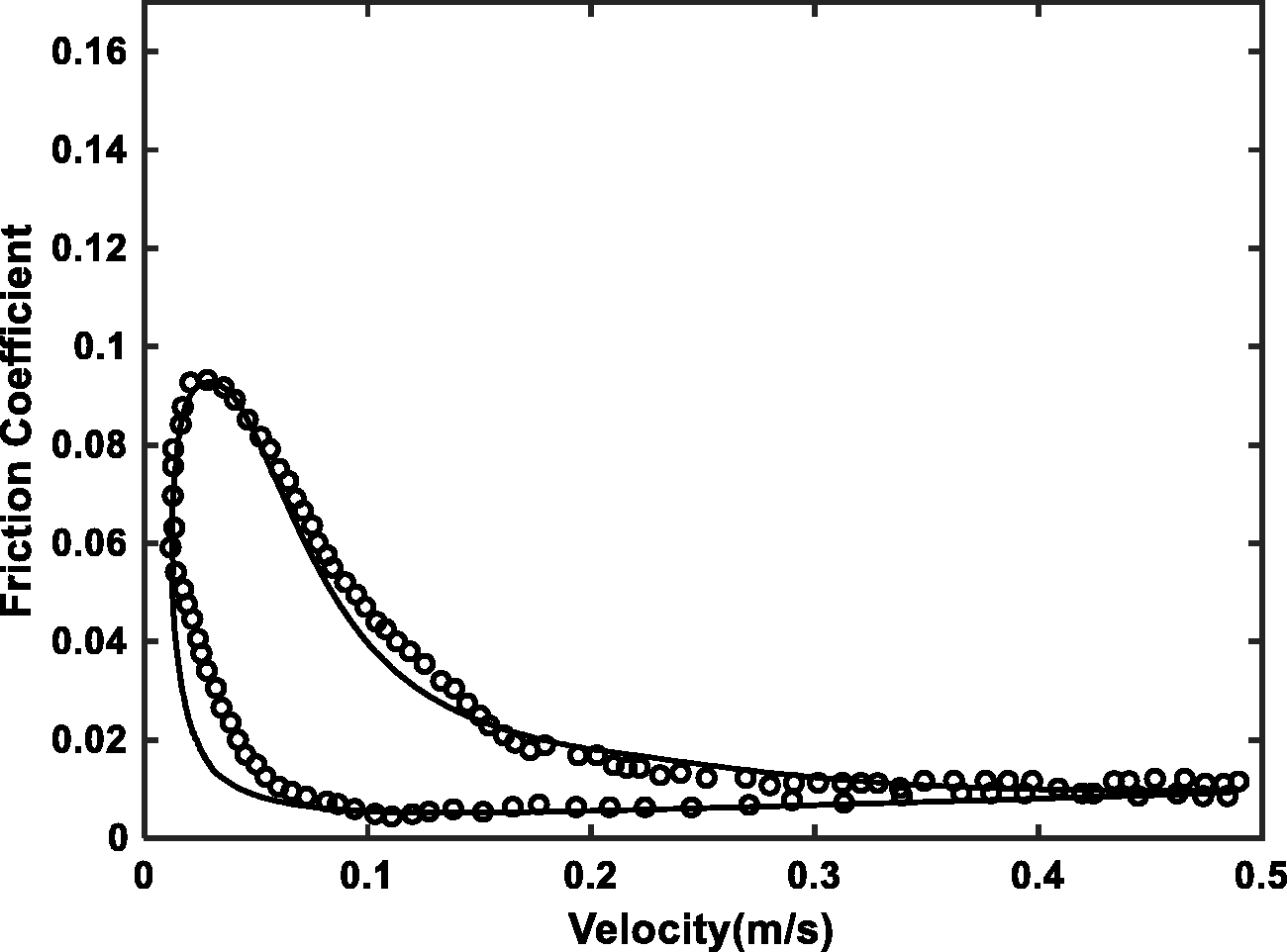
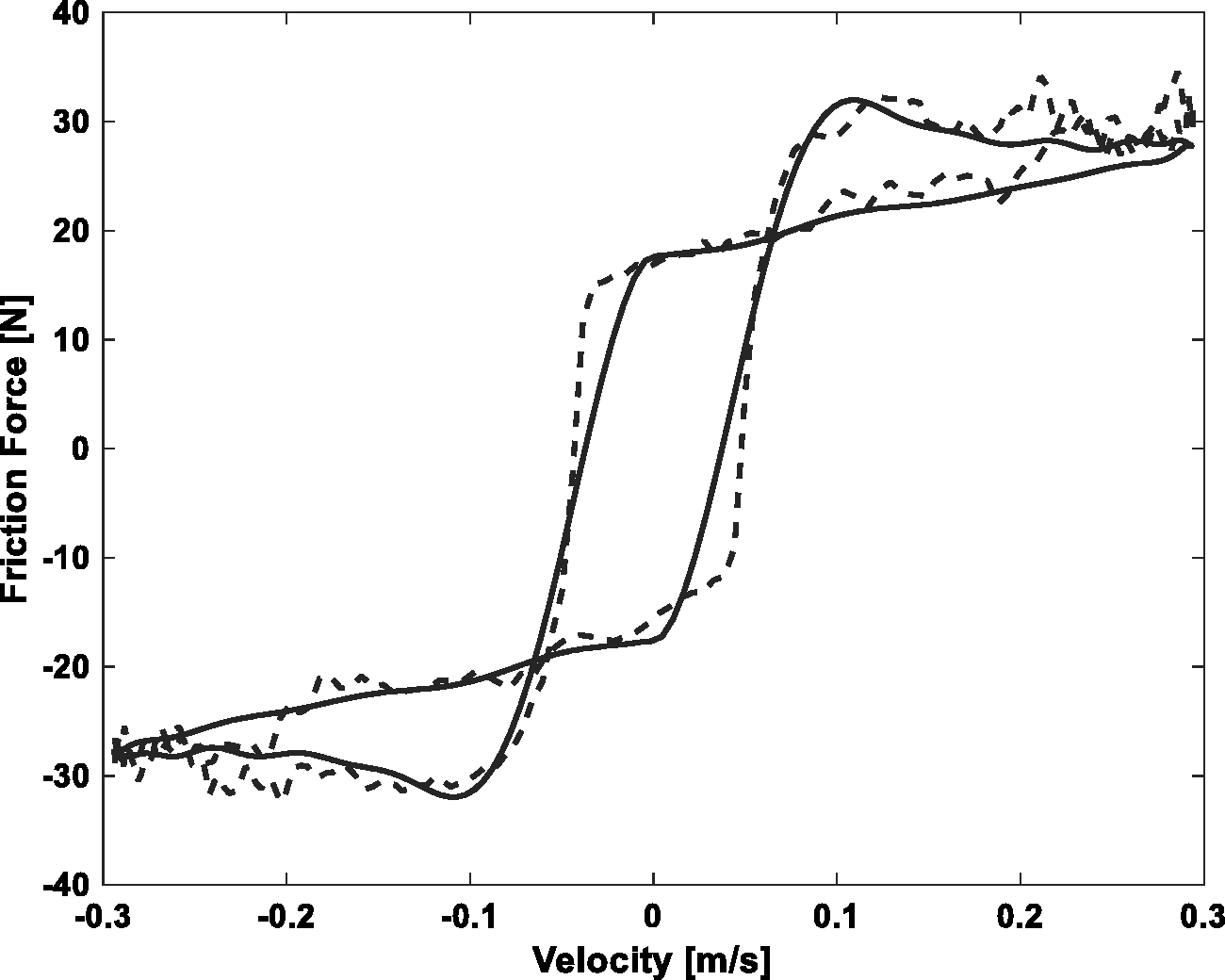
For further system level validation of the presented model and case study in this paper, the calculated friction is compared to the experimental results. These comparisons are shown in Figures 12 and 13. Input parameters of friction model including, linear guideway geometry, material and lubricant properties are presented in Tables 2 and 3. As shown, the results of the present study are also in close agreement with this experimental measurement.
Friction force time history, Experiment (solid line), Model predictions (dash line). Friction force vs. sliding velocity, Experiment (solid line), Model predictions (dash line). Lubricant, material and surface properties.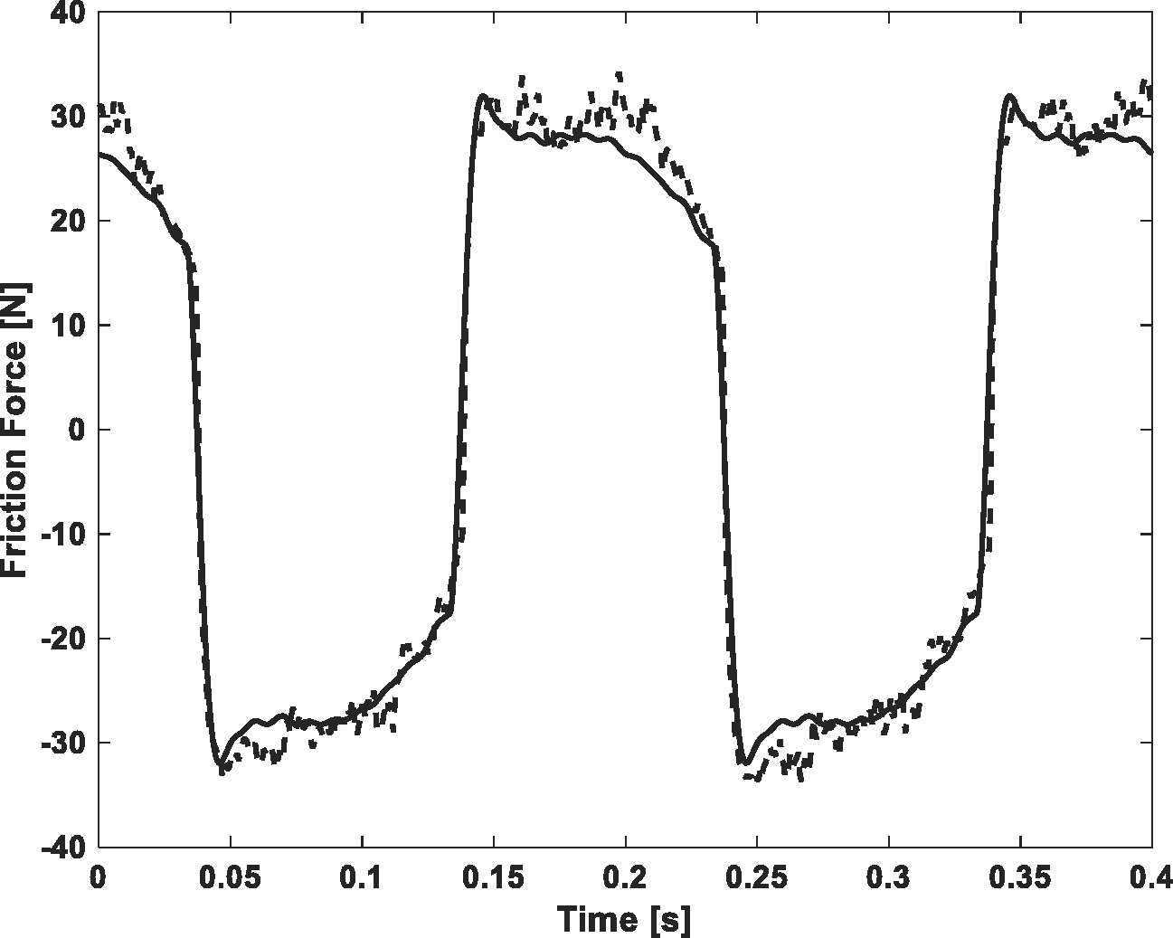
Numerical investigations
First, an unloaded tribo-dynamic analysis is conducted. The analysis provides clear understanding of main frequencies of response. Then, a loaded tribo-dynamic analysis is carried out and results are investigated under different external loads and preloads. Finally, the full numerical tribo-dynamic results are presented and the effect of lubricant film is examined.
Unloaded case
The equations of motion coupled with implicit tribology model are solved with no external load. Frequency spectrum of normal displacement, y, is shown in Figure 14. The natural frequency of linear guideway system and the excitation frequency of sliding velocity can be observed in Figure 14. The calculated natural frequency as well as super and sub harmonics are shown in the figure.
FFT Spectra of unloaded displacement.
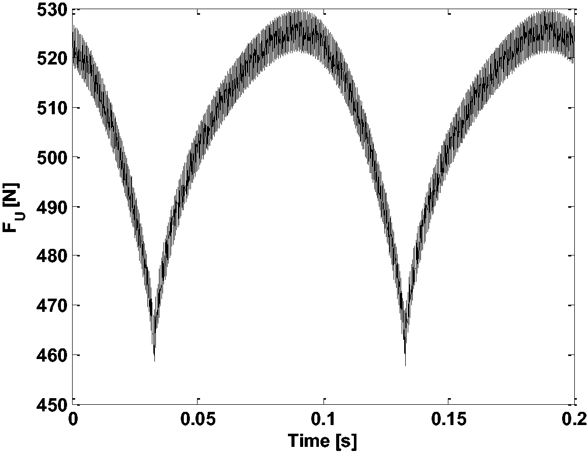
The roller contact stiffness variation is observed by the contribution of a roller contact load during a cycle of sliding velocity. This is shown in Figure 15 for the unloaded case. The figure reveals significant nonlinearity of stiffness originated from the nonlinear contacts. Figure 16 presents the contact load obtained from the tribo-dynamic model. This load forms the input to the full numerical explicit tribological model discussed in the following section.
Time history of stiffness variation in the linear guideway. Load share of a roller in upper row of linear guideway during one cycle.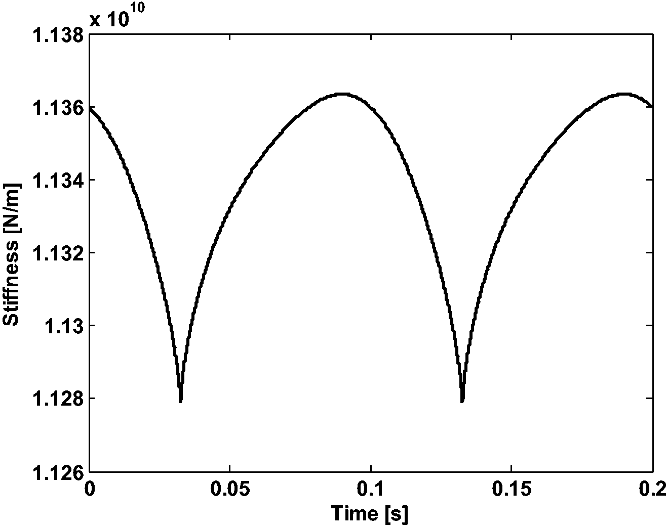
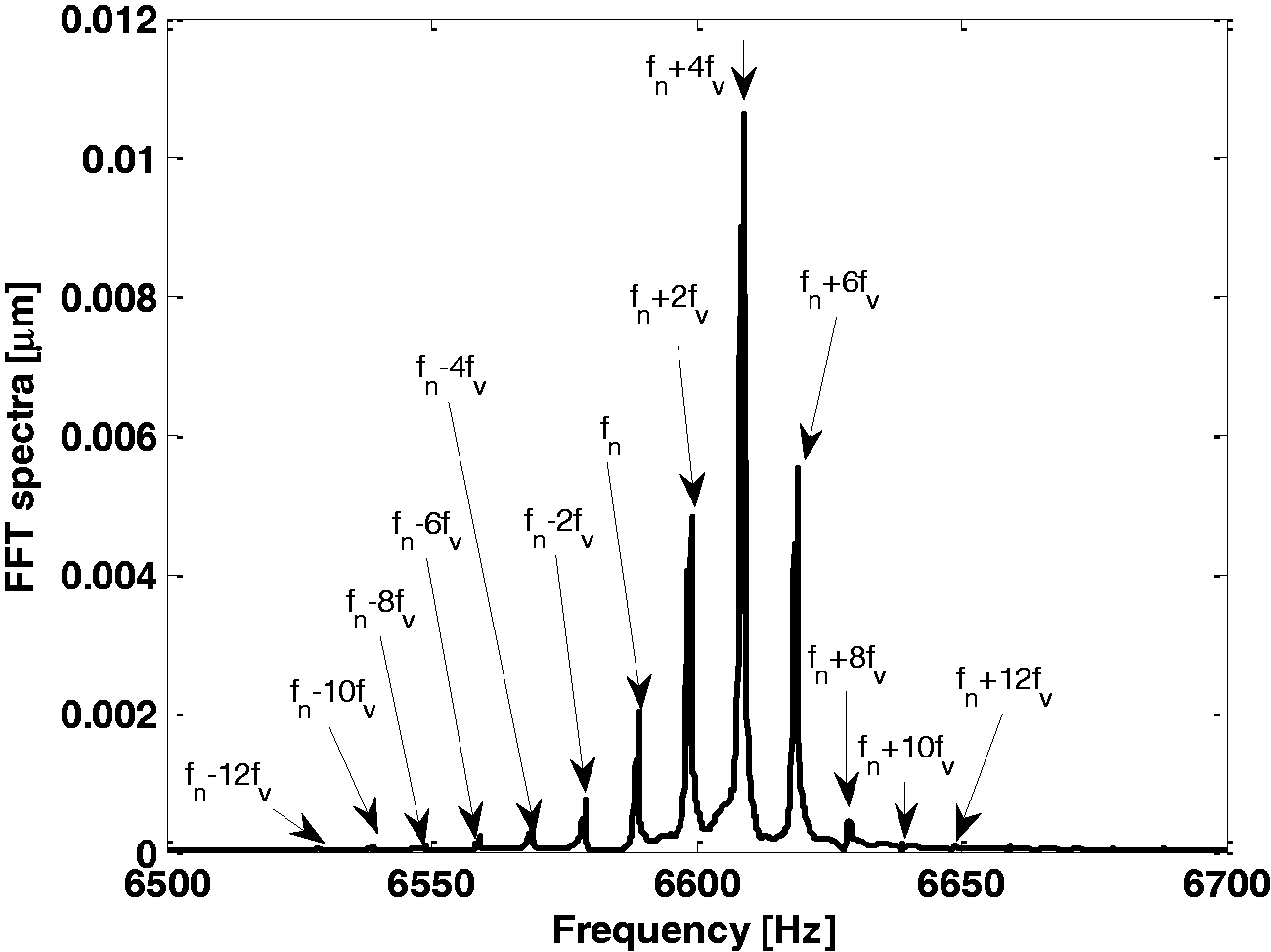
The FFT spectrum of contact load for a roller of upper row is obtained after reaching steady-state conditions, as shown in Figure 17. The natural linear guideway frequency and the horizontal velocity frequency make the largest contribution to the spectrum.
Magnification of spectrum of contact load in the upper row.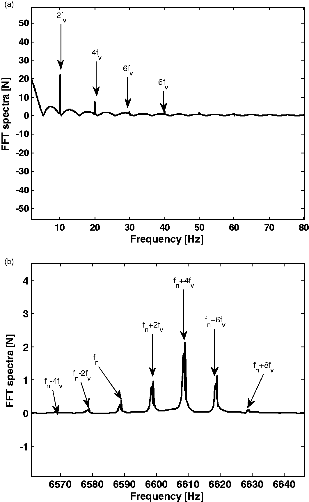
Figure 18 shows the minimum film thickness obtained from the implicit solution of analytical tribology and dynamics. It is revealed that the film thickness always remains in the sub-micron region, exhibiting a mixed-EHL regime. The horizontal line in the figure shows Stribek parameter equal to 3, representing the threshold for mixed regime of lubrication.
Minimum film thickness of contact in the upper row.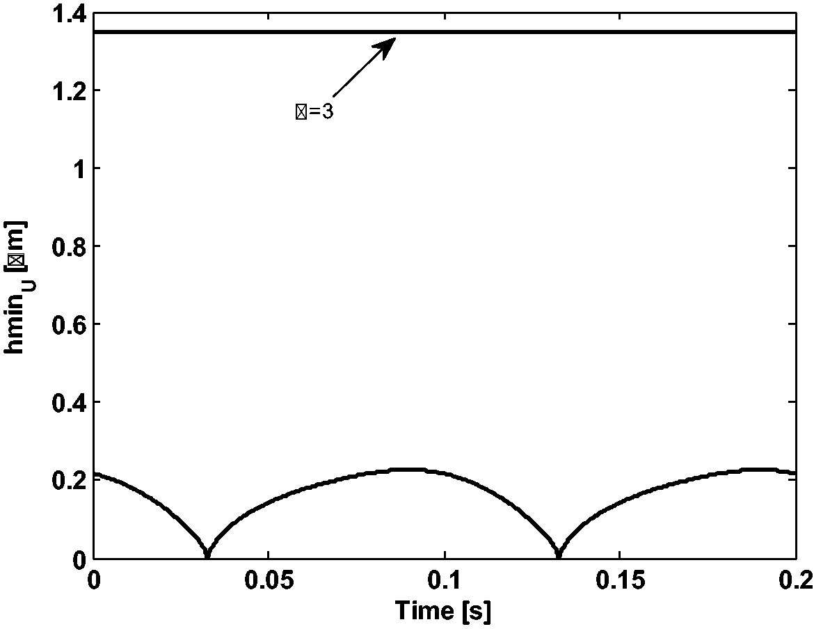
External harmonic force
In this section, the tribo-dynamic model is solved by considering the normal excitation force with three different amplitudes. Excitation frequencies before, during and after natural frequency and resonance are also analyzed. It should be noted that the horizontal velocity frequency is considered to be 5 Hz, defined by the machining process for all cases.
Before resonance, 3000 Hz and 9000 N load: The aim of this section is to understand the behavior of the system away from resonance, which is meant to be the safe zone for operation linear guideway system. Frequency spectrum of normal displacement, y, for case of 3000 Hz (before resonance) and amplitude of external force of 9000 N is shown in Figure 19. The natural frequency of linear guideway system and the excitation frequency of sliding velocity can be observed in this figure. Figure 19(b) shows more pronounced effect of sliding frequency in compare with the natural frequency of the system. This proves the necessity of coupling between the horizontal and vertical degrees of freedom.
FFT for case of before resonance frequency 3000 Hz and under 9000 N.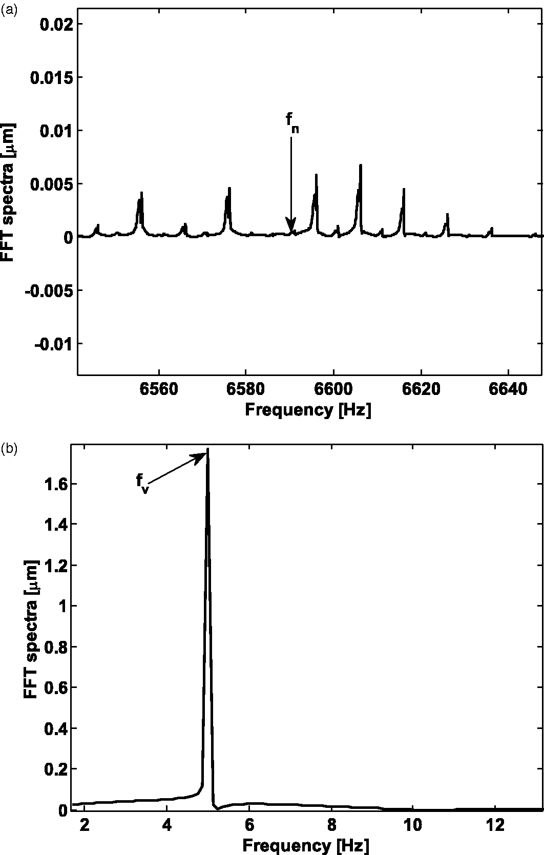
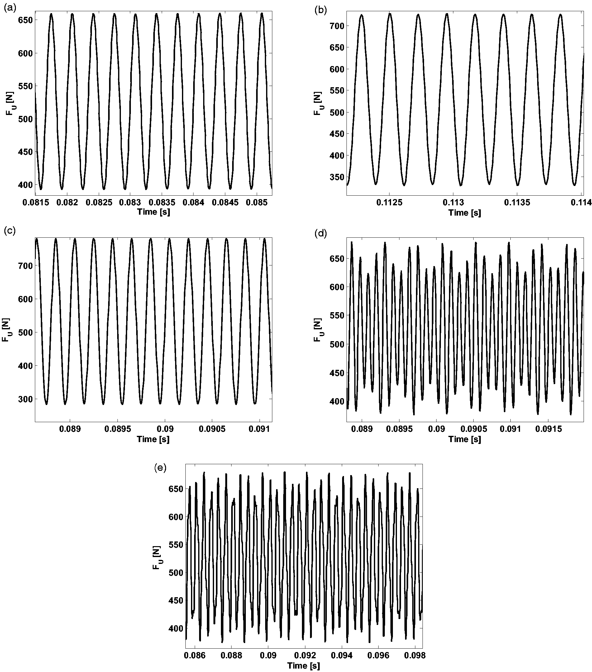
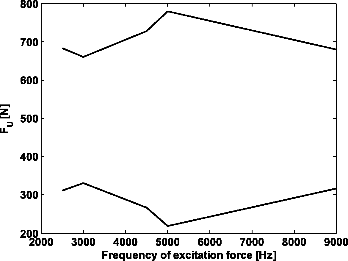
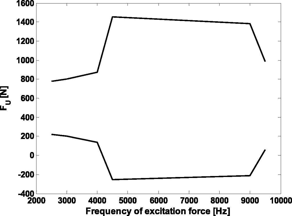
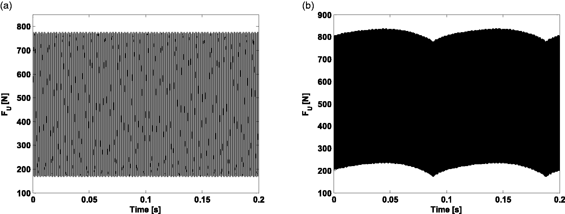
Before, during and after resonance, low load of 6000 N: In this section it is aimed to ascertain the effect of the excitation frequency before, during and after resonance on the contact conditions. The contact load for each roller in the upper row for the case of normal force amplitude of 6000 N and five excitation frequencies of 2500, 3000, 4500, 5000 and 9000 Hz are shown in Figure 20. Figure 21 shows the zoomed view of these time histories. Figure 22 presents the envelope of these time series. It is revealed that the contact force observes its peak at resonance frequency.
Contact loads under 6000N load and at (a) 3000 Hz, (b) 4500 Hz, (c) 5000 Hz, (d) 9000 Hz and (e) 2500 Hz. Zoomed view of contact loads under 6000 N load and at (a) 3000 Hz, (b) 4500 Hz, (c) 5000 Hz, (d) 9000 Hz and (e) 2500 Hz. Envelope of load for frequency sweep under 6000 N.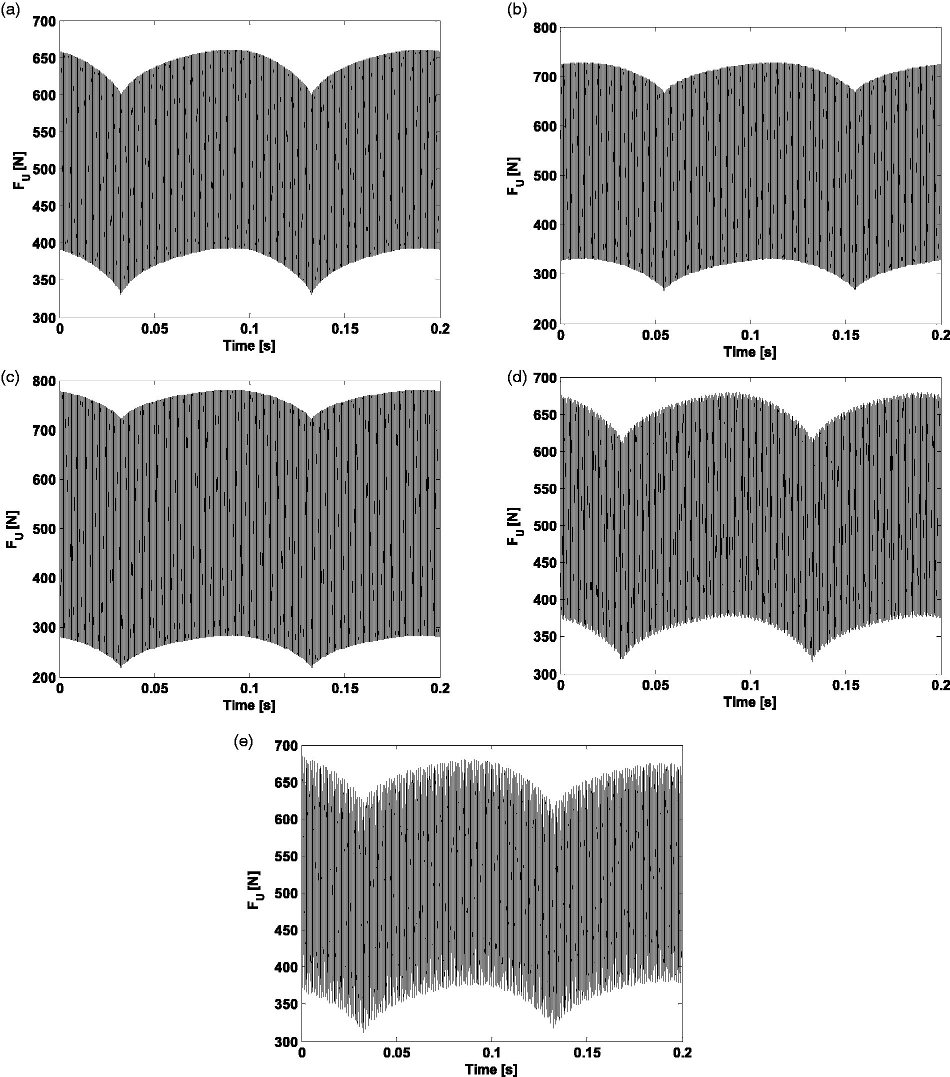
The film thickness of each roller in the upper row for the case of normal force amplitude of 6000 N and the frequencies of Figures 20 and 21 are shown in Figure 23. As is shown in this figure, the film thickness is almost insensitive to the load change observed in Figure 21. This is due to the EHL nature of the contact, being two to three orders of magnitude stiffer than the contacting solids. Hence, in a system of series stiffnesses of film and solids, the significant change happens in solids. It is also observed that the horizontal frequency has the biggest contribution to the film thickness variations.
Film thickness in upper row under 6000 N and for (a) 3000 Hz, (b) 4500 Hz, (c) 5000 Hz, (d)9000 Hz and (e) 2500 Hz.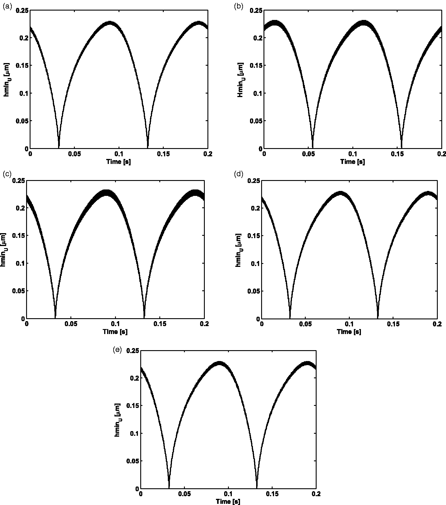
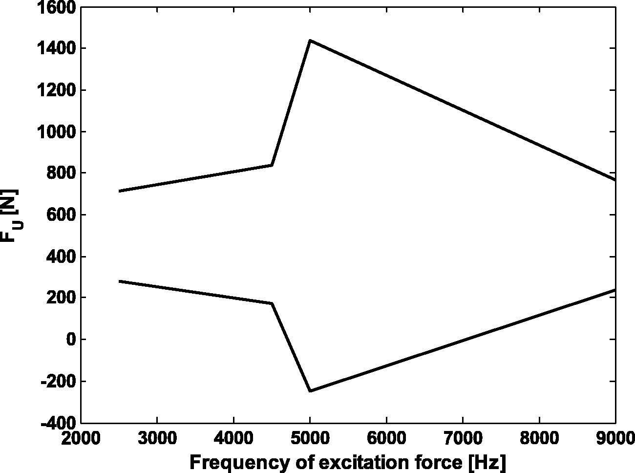
Before, during and after resonance, medium load of 9000 N: The contribution of the contact load for each roller in the upper and lower rows for the case of normal force amplitude of 9000 N and the frequencies before, during and after the natural frequency at 2500, 4500, 5000 and 9000 Hz are shown in Figure 24. Figure 25 is the envelope of time histories. It is revealed that the contact load reaches its maximum during resonance frequency as expected. It is also clear that the system response is more affected during resonance at higher load of 9000 N. It can be seen from Figures 24 and 25 that at higher load of 9000 N in comparison with 6000 N, the effect of natural frequency becomes closer and competing with contribution of the horizontal velocity. The main reason is the effect of horizontal degree of freedom and its coupling on the film thickness. The film thickness is also affected by the contact load. At lower contact loads, the film exhibits lower stiffness meaning more contribution to the overall system’s dynamics via coupling. It also means bigger film thickness values and more contribution to deformation. Hence, at higher loads and with increasing film stiffness, the effect of film diminishes and the effect of the system’s natural frequency originated from the solid contacts increases. The above effect is even further enhanced at resonance frequency where the contact load is further increased by the effect of resonance.
Contact load under 9000 N at excitation frequencies of (a) 2500 Hz, (b) 4500 Hz, (c)5000 Hz and (d) 9000 Hz. Envelope of load for frequency sweep under 9000 N.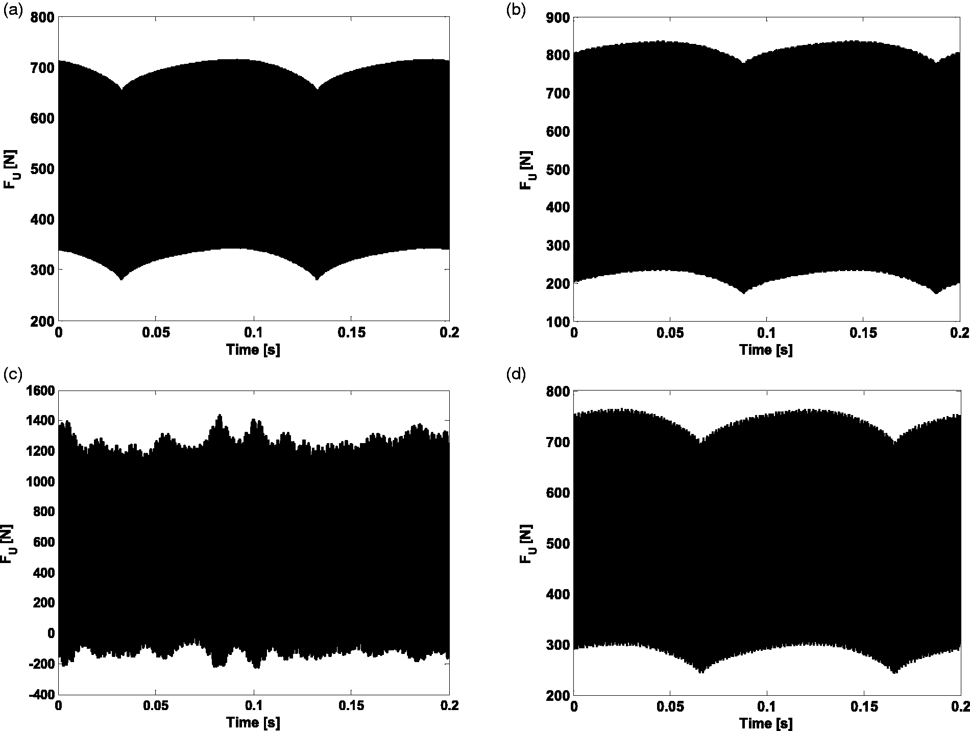
The film thickness of each roller in the upper row for the case of normal force amplitude of 9000 N and different frequencies before, during and after the natural frequency is shown in Figure 26. Although the overall range of the film, governed by the horizontal velocity is still insensitive to the significant load change, the local peak-peak value governed by natural frequency gains more significance. This also confirms the more pronounced effect of natural frequency at higher load.
Film thickness in upper row: (a) 2500 Hz, (b) 4500 Hz, (c) 5000 Hz and (d) 9000 Hz.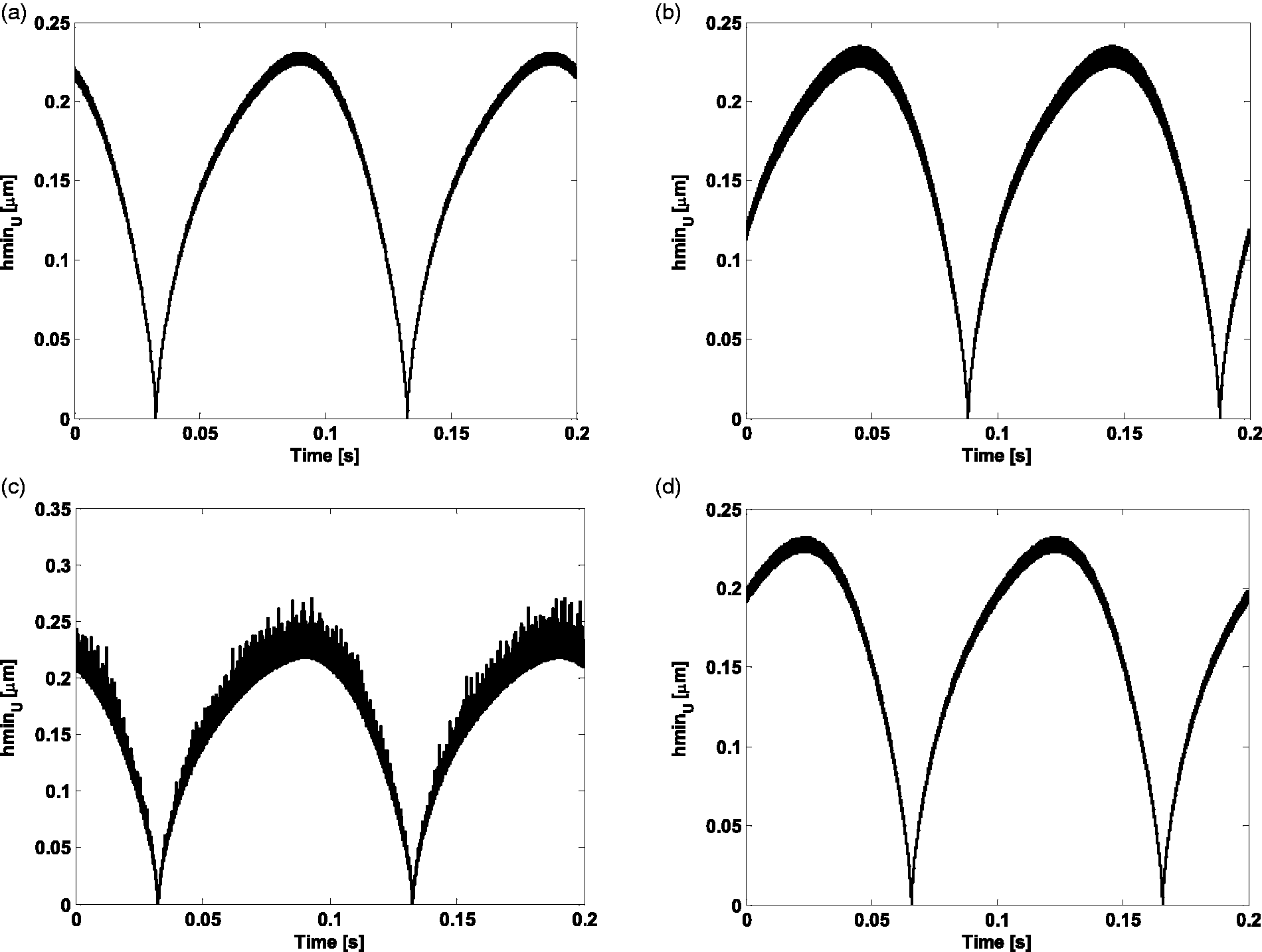
Before, during and after resonance, high load of 12,000 N: The contribution of the contact load for each roller in the upper row for the case of normal force amplitude of 12000 N and frequencies before, during and after the natural frequency is shown in Figure 27. Similar to the trend from 6000 N to 9000 N, the effect of increased load is less pronounced effect of horizontal velocity frequency and coupling. Figure 28 is the envelope of time histories presented in Figure 27.
Contact load under 12,000 N and at (a) 2500 Hz, (b) 3000 Hz, (c) 4000 Hz, (d) 4500 Hz, (e) 9000 Hz and (f) 9500 Hz. Envelope of load for frequency sweep under 12,000 N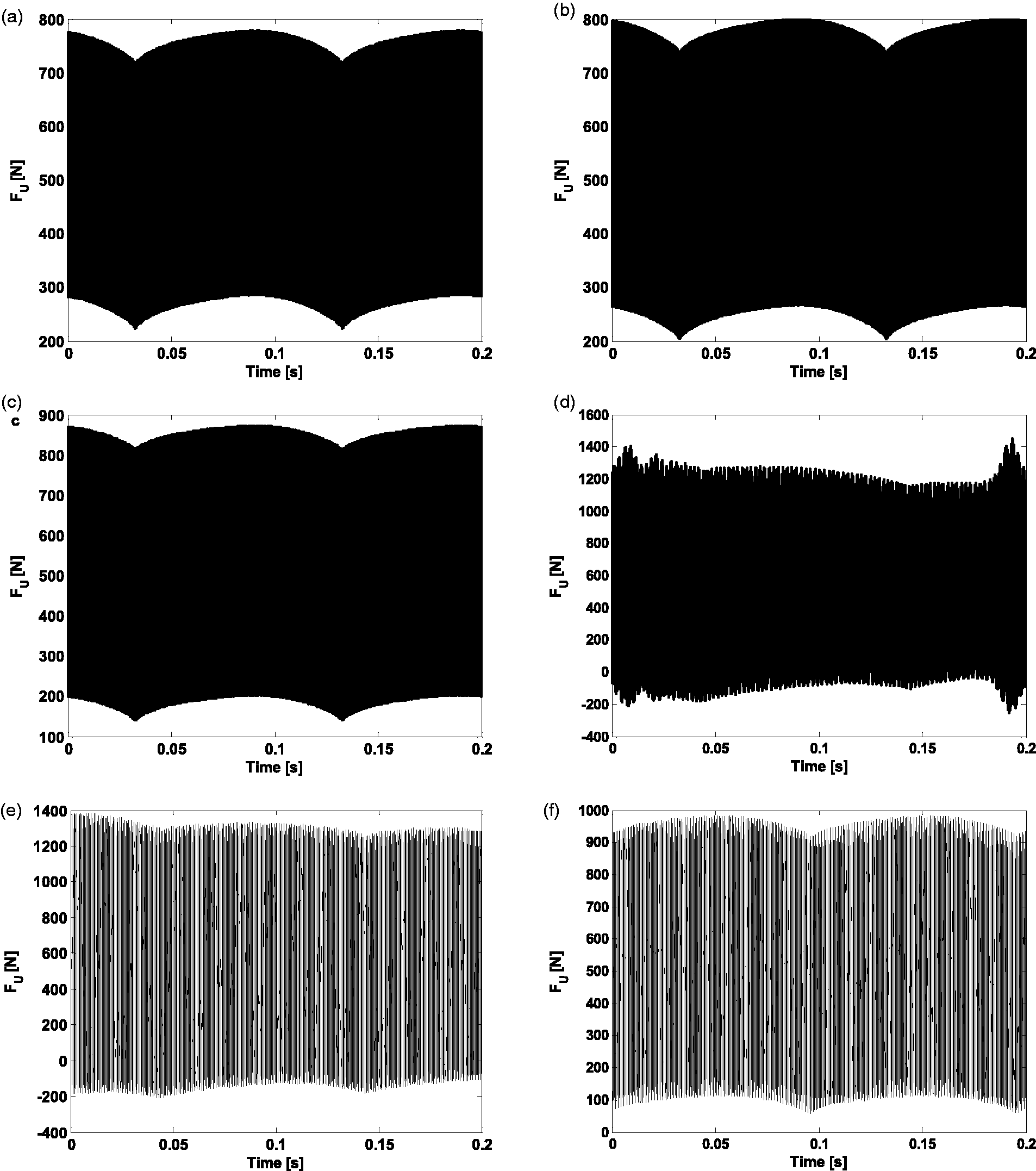
The film thickness of each roller in the upper row for the case of normal force amplitude of 12000 N and different frequencies is shown in Figure 29. The film thickness results also confirm the increasing effect of the natural frequency in the tribo-dynamic response and reduced effect of horizontal degree of freedom.
Film thickness of upper row at (a) 2500 Hz, (b) 3000 Hz, (c)4000 Hz, (d) 4500 Hz, (e) 9000 Hz and (f) 9500 Hz.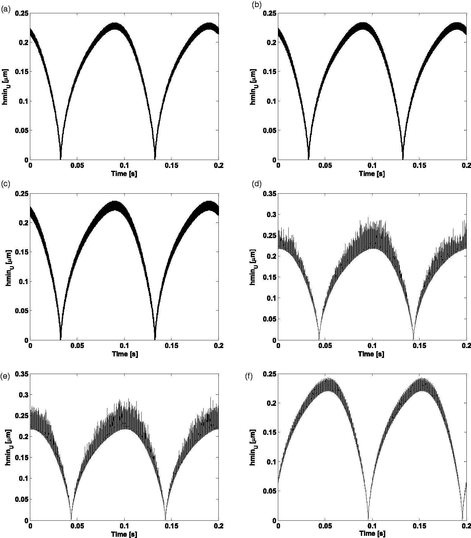
Effect of dry and EHL contact assumptions
In this section, it is aimed to clearly show the effect of incorporation or neglecting the effect of lubricant film thickness in the contact. The results for the upper row contact loads are compared for the case of tribo-dynamic model and only dynamic model with the dry contact assumption. The comparison is made at 9000 N and for 2500 Hz and 4500 Hz excitation frequencies. Results are presented in Figures 30 and 31. As is observed from these figures, the incorporation of film thickness increases the contact load due to the addition of film thickness to the overall deformation. It also adds the sliding velocity frequency to the system’s dynamics. Although these effects change for different loads and frequencies, they always exist and affect the system’s response.
Comparison of contact load in upper rollers at frequency of 2500 Hz: (a) dry contact and (b) lubricated contact. Comparison of contact load in upper rollers at frequency of 4500 Hz: (a) dry contact and (b) lubricated contact/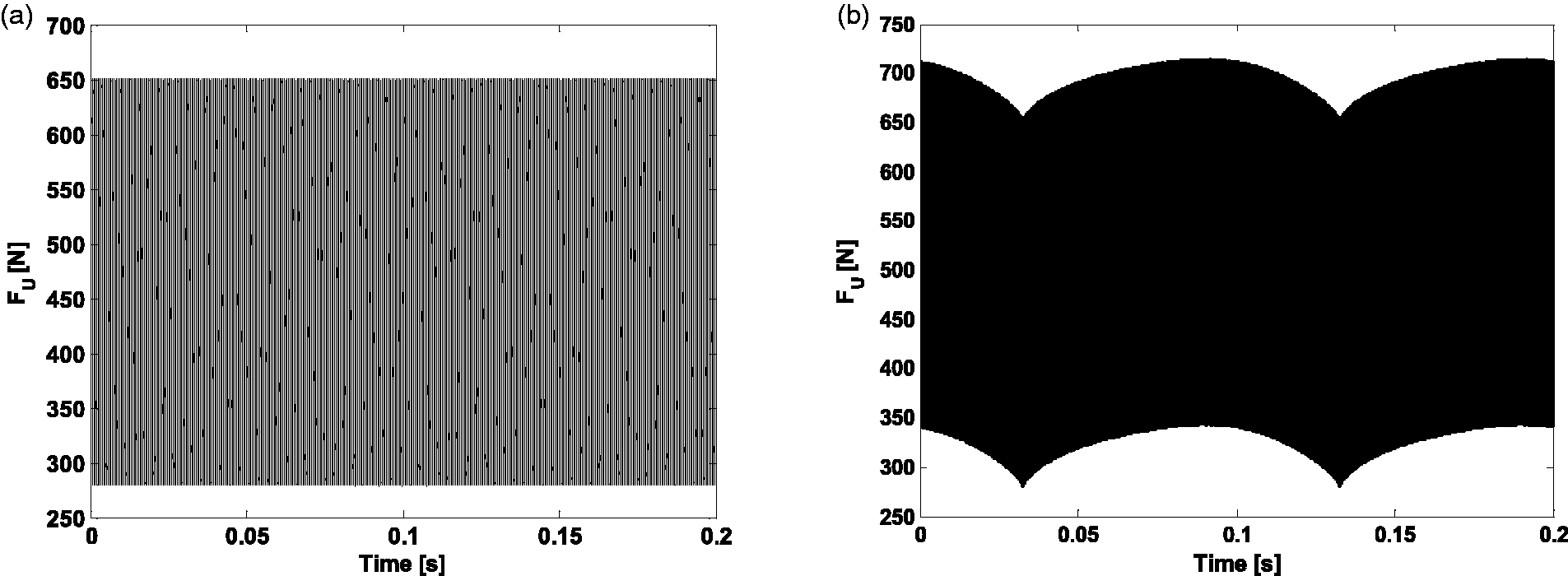
Explicit numerical tribology model
In this section, the results of full numerical explicit EHL and asperity models are presented for unloaded and loaded cases with amplitude of 9000 N.
Unloaded conditions: After performing a full implicit tribo-dynamic solution, the contact load presented in the previous section is used as the input to this full numerical explicit model. Figure 32 shows the time history of the contact load for upper row rollers with the sliding velocity frequency of 5 Hz for one sliding velocity cycle. Three points along one cycle of high natural frequency are selected and annotated by A1, B1 and C1 to perform full numerical analysis.
Contact load time history: (a) one cycle, (b) zoomed view.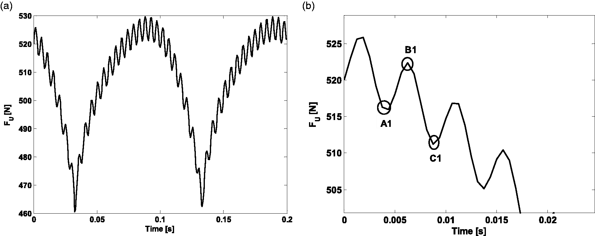
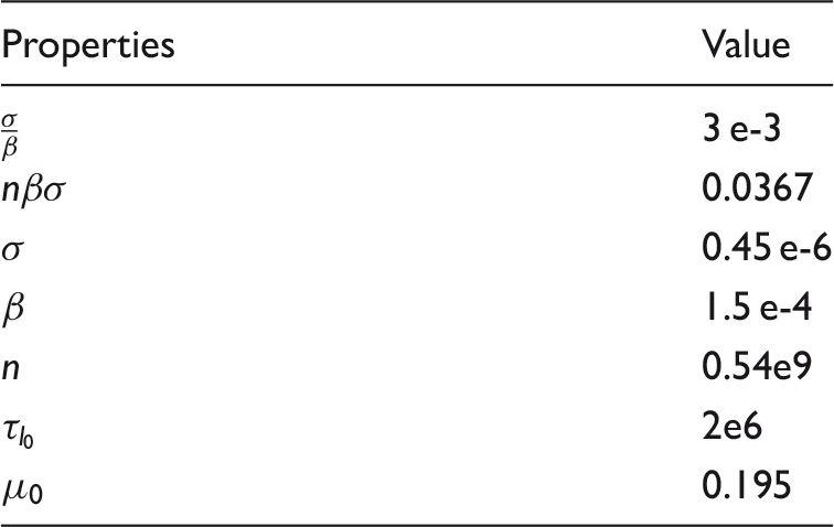
Input and surface parameters shown in Table 4 are used to determine pressure and lubricant film thickness distributions in roller contact at any instant of time. Results are shown for A1, B1 and C1. Figure 33 shows these distributions. It is revealed that contact pressure and film thickness distributions follow EHL behavior, confirming the use of incorporated analytical formulation in the implicit tribo-dynamic model.
Pressure (solid line), film thickness (dash line) distribution and extrapolated film thickness obtained from implicit analytical solution (circle) at A1, B1 and C1. Surface parameters utilized in the analysis.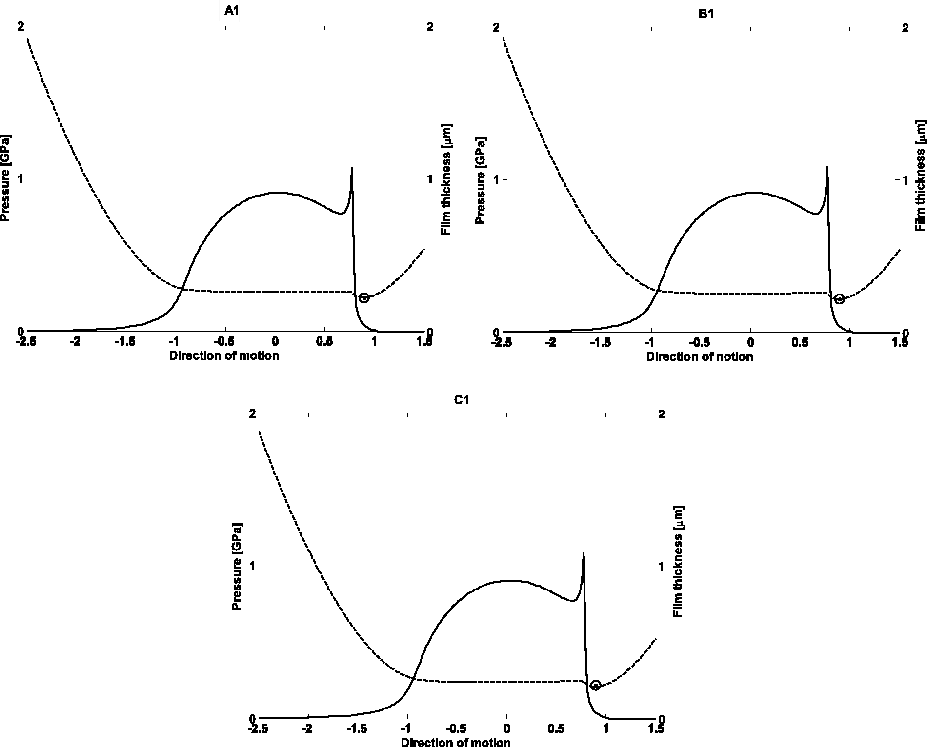
Central film thickness values from tribo-dynamic model are presented in Figure 33. A good agreement is observed between the implicit and explicit tribological model. This also confirms the appropriateness of the utilized formulation in the implicit model.
Central pressure values are in the region of 0.8–1 GPa, with higher values at secondary spikes reaching up to 1.1 GPa. Considering the complex EHL pressure distribution, it is clear that the importance of considering detailed EHL is crucial to obtain a realistic pressure and shear values. This has particular importance for durability and efficiency calculations which can be done also explicitly and passively after implicit tribo-dynamic solution.
Loaded condition under 9000 N: Contact load for upper row rollers with external force of 9000 N and frequency of 9000 Hz and the sliding velocity frequency of 5 Hz for one sliding velocity cycle is shown in Figure 34. As discussed in the previous section, at higher loads the effect of high frequency is more pronounced. Full numerical EHL solution is conducted at A2-J2.
Contact load time history: (a) one cycle, (b) zoomed view.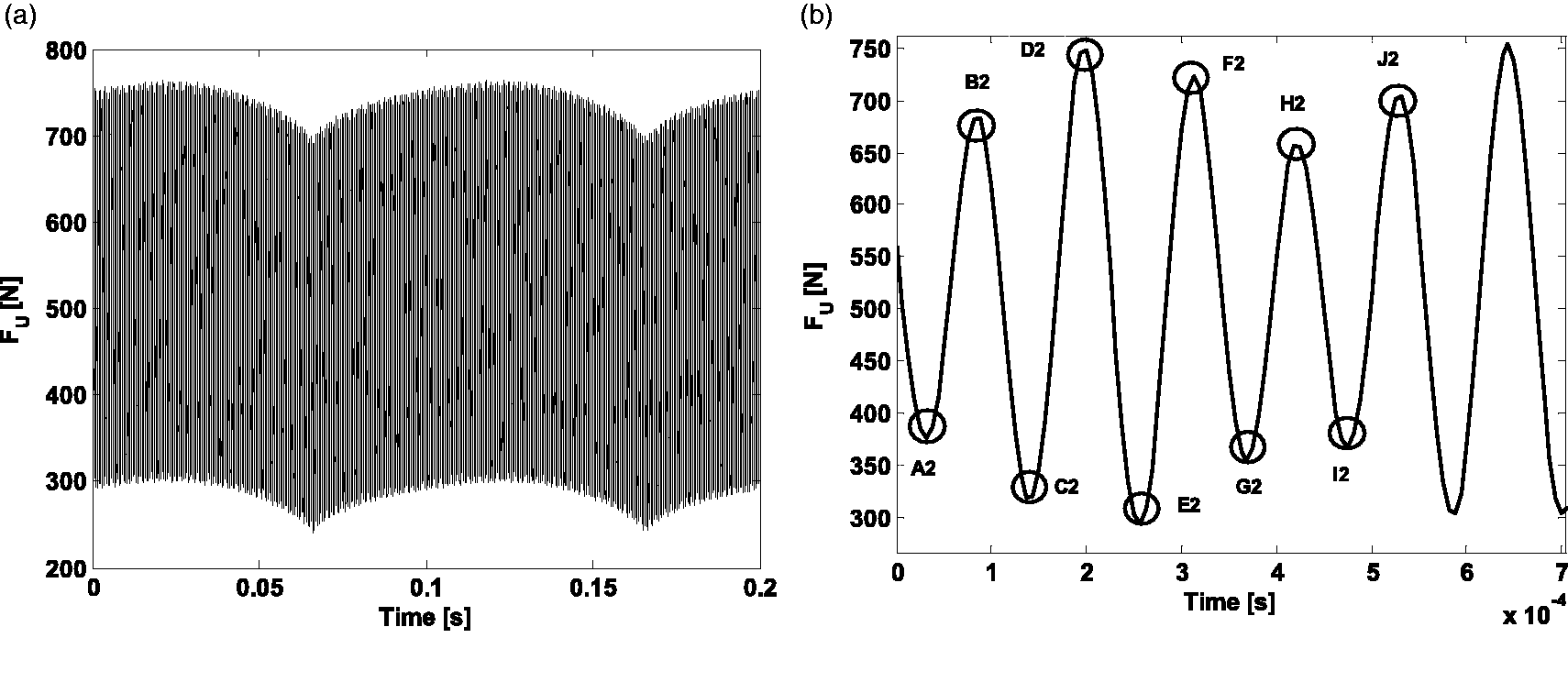
The pressure and film thickness distributions are presented in Figure 35. The waviness on the distribution is originated from the squeeze effect of Reynolds equation which is well understood for EHL contacts. As can be seen from this figure, the squeeze effect increases due to the increase in the amplitude of high frequency fluctuations. Due to higher load, the pressure in the contact can rise up to central value of 1.1 GPa and secondary spike of up to 1.3 GPa.
Pressure (solid line), film thickness (dash line) distribution and extrapolated film thickness obtained from implicit analytical solution (circle) under 9000N for A2-J2 points of Figure 34.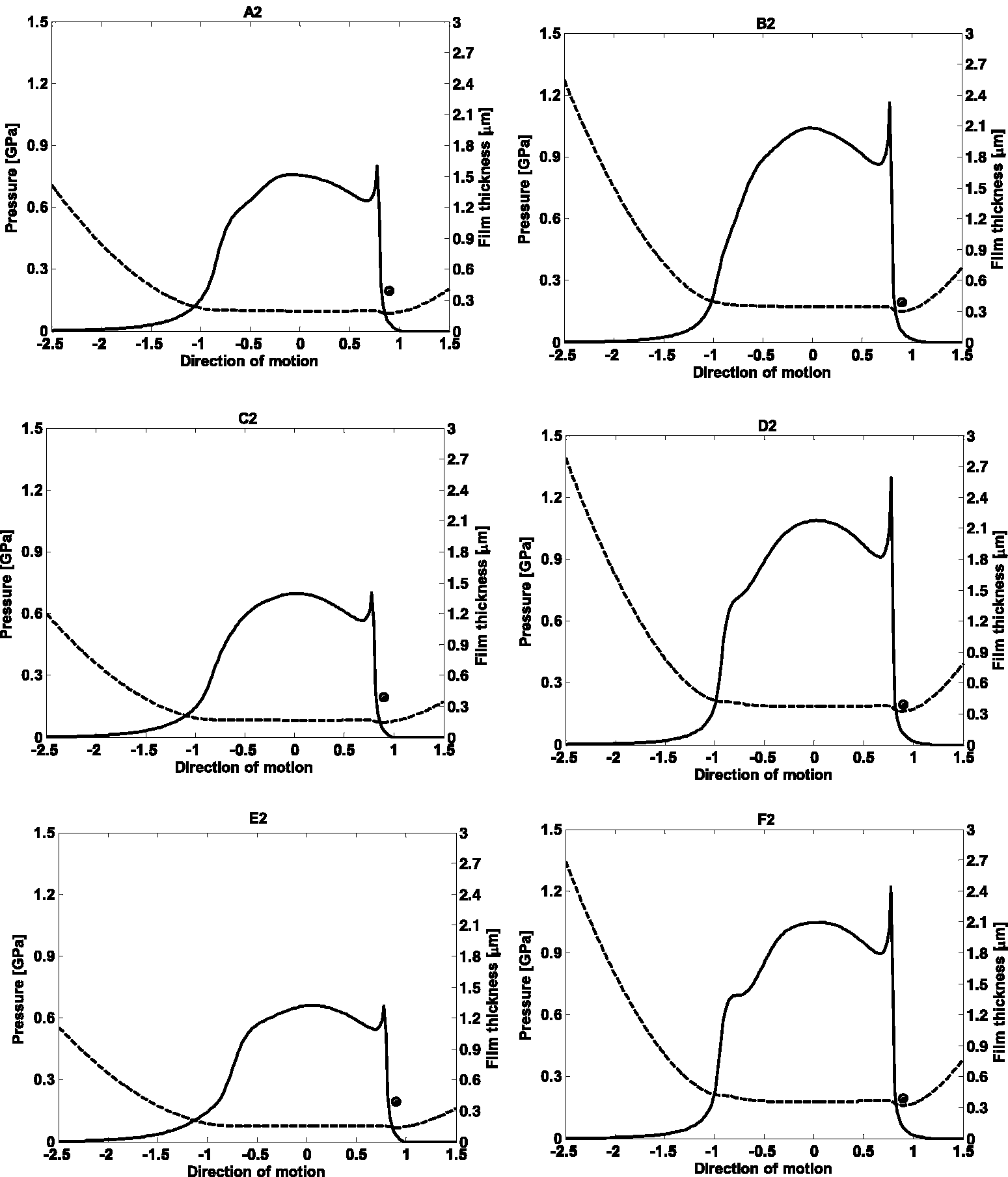
Conclusions
A tribo-dynamic model for linear guideways is presented. The model couples the horizontal degree of freedom, governed by feed velocity and the vertical degree of freedom. The model takes into account the presence of lubricant film, maintaining the coupling between two degrees of freedom. An analytical tribology model is used implicitly within dynamic model in order to consider effect of lubricant film on the dynamic response. An explicit full numerical model is used to obtain pressure and film thickness distributions. The following points can be concluded from the presented results in the current work:
The regime of lubrication in the contact is mixed-EHL. This is verified by the results of full numerical mixed-EHL model. The implicit analytical tribology model provides accurate results for the central value of the film, used in the dynamic solution. The effect of mixed-EHL film cannot be neglected from the solution. This is shown by comparing the results of dry contact assumption versus the lubricated contact assumption. The main frequencies of the dynamic response are the excitation frequency, natural frequency of the contact and the feed velocity frequency. The coupling between two degrees of freedom is an important factor. This effect is more pronounced at moderate and low loads. This is due to less loaded EHL film, providing lower stiffness and bigger film thickness values which leads to a more pronounced effect on dynamic response. The effect of lubricant film and coupling is further reduced during resonance, when the load on the contact is magnified further.
Footnotes
Declaration of Conflicting Interests
The author(s) declared no potential conflicts of interest with respect to the research, authorship, and/or publication of this article.
Funding
The author(s) received no financial support for the research, authorship, and/or publication of this article.