
Abstract
The modeling and vibration transfer function of in-plane rigid–elastic-coupled tire model is put forward for researching the heavy-loaded radial tire with the feather of larger radial length and width ratio. The coupled characteristic of tread and sidewall is taken into consideration, and the coupled natural frequencies are analyzed with the normal pressure and fixed rim. The rigid–elastic coupling equation is modeled with the flexible beam on elastic foundation, which tread is modeled as the Euler beam and the sidewall is regarded as the sub-sectional spring with lumped mass. The dynamic equation is discrete with finite difference method, and three-parameter rigid–elastic-coupled tire model is derived based on the geometrical and structural parameters. The structural parameters of the tire are identified by the genetic algorithm based on the experimental modal parameter of heavy-loaded tire, and the higher order modal frequency is predicted with the analytic method. The analytical transfer function between tread and tread, tread and sidewall is derived. Experimental and theoretical results show that the in-plane rigid–elastic-coupled tire model can achieve the higher precision on predicting the transfer function and vibration feature of heavy-loaded tire within the frequency band of 300 Hz, compared with the method which only considers the coupling of tread and rim and is limited to 180 Hz.
Keywords
Introduction
As the heavy-loaded radial tire, GL073A ADAVANCE tire has the characteristics of load heavily and widely applied to weapons platform. Its axial load is in an average of 10–13 t, to ensure its off-road properties, and heavy-loaded radial tire has a larger flat ratio of sidewall radii and tread width close to 1, compared with passenger car tire and truck tire, as shown in Figure 1. The structural parameters are listed as follows: 16.00R20 173G, 18 ply rating, maximum speed is G (90 km/h), section width is 438 mm, outside diameter is 1320 mm, normal inflation pressure is 790 kPa, and maximum load is 6500 kg.

Flat ratio of different kinds of tires.
As the only component interfacing with the road from military vehicles, the main performance index of the vehicle, such as smoothness, power, economy, maneuverability, and stability of operation, 1 is closely related to the tire dynamics. 2 From this point of view, the design of a pneumatic tire is vital to vehicle dynamics, and the description of tire behavior is of vital importance. In order for noise effect, the in-plane vibration caused by the short wave of the irregular road needs to be taken into consideration. 3
As with the feature of high pressure, low damping, bulky decorative pattern and larger flat ratio, the vibration response while rolling is owned to the structure vibration, especially for speed to 70 km/h, the structural noise is accounted 65% 4 of the tire noise. The tread is excited by the irregular road, 5 which is the only component interfacing with the road and the vibration, and excitation is transferred to rim through sidewall shown in Figure 2. So, the analytical method based on structural vibration is of great significance.
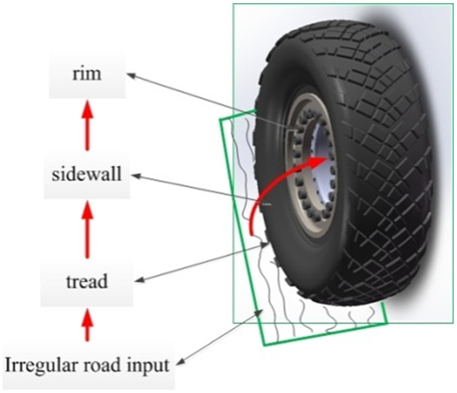
Vibration response excited by irregular road.
The structural model can be divided into rigid tread tire model 6 (RT-tire), shown in Figure 3(a), flexible tread tire model 7 (FT-tire), shown in Figure 3(b). Rigid carcass ring 6 is the main feature of RT-tire model (Figure 3(a)) and a flexible unit representing the residual stiffness, the tread can be characterized with the rim of the dislocation formation, the effective road input is substituted by road height, and effective rolling radius, 8 achieve the simulation of rolling condition. FT-tire model (Figure 3(b)) simplified the tire as the flexible tread on elastic foundation, in which tread referred as flexible tread, sidewall and inflation pressure referred as elastic foundation, 7 and the FT-tire model can achieve the deformation of tread.

While, RT-tire model can character the first-order modal shape, and the frequency band is within 70–80 Hz, which is the basic short wavelength intermediate frequency tyre (SWIFT) model used widely in the low-frequency in-plane vibration analysis and out-plane force characteristic. As the “special case” of flexible tread model, RT-tire model only considers dislocation formation and ignores the high-order modal as well as the corresponding tread vibration neglected modes.
FT-tire is derived by the physical model and can take the material nonlinearity and geometrical nonlinearity into consideration, improving the scientific basis of the modeling of tire; meanwhile, FT-tire model also can omit pretreatment of the effective road of RT-tire, and the vibration characteristics of the tire can derive the analytical solution or numerical solution, so the research for the FT-tire becomes meaningful.
According to the different model methods of the tread, FT-tire model can be divided into continuous FT-tire model (Figure 4) and distributed mass tire model (Figure 5). The continuous FT-tire is consisted with one-dimensional (1D) flexible tread model (Figure 4(a) and (b)), two-dimensional (2D) flexible tread model (Figure 4(c) and (d)), and three-dimensional (3D) flexible tread model (Figure 4(e) and (f)). Tensile string model 9 only considering bending effect, Euler beam model 10 considering the bending stiffness, and Timoshenko model 11 taking into account the shearing action belong to the 1D tire model; orthotropic plate 12 falls into the 2D tire model with ring model,2,7,11 while the shell model 13 and modified ring model 14 are geared to 3D tire model.

Continuous flexible tread tire model: (a) tensile string model, (b) Euler/Timoshenko beam model, (c) orthotropic plate model, (d) ring model, (e) shell model, and (f) modified ring model.

Distributed mass tire model: (a) distributed mass tire model and (b) FTire.
The continuous flexible tread model can achieve the vibration analysis of high frequency and the simulation of geometrical, structural, and mechanical nonlinearities, while the theoretical basic of continuous flexible tread model is the solution of the partial differential equation, and the velocity profile is coupled with the time, which increases the difficulty of the rolling characteristic analysis.
The distributed mass tire model is consisted with finite segment, and the coupled relationship of tread segment is featured with the spring as shown in Figure 5. Eichler 15 and Sandu and Umsrithong 16 modeled the tire with the finite distributed tread segment shown in Figure 5(a), and spring connecting the adjacent segment is referred as the tread structural stiffness; Gipser 17 developed and completed FT-tire tire model (Figure 5(b)), and the tread is features as the flexible distribute ring with bending stiffness and stretching stiffness. FT-tire model can accurately simulate the vibration characteristic within the frequency band of 120 Hz. The constraint mode tire model is proposed by John B Ferris and developed by R Ma et al., 18 which divides the tire into N elements, and each segment is modeled as an Euler elastic beam with length 2πR/N, while the inflation pressure is ignoring and the structural parameters are identified by the steady deformation which increases the difficulty of the model appliance.
Brief description of heavy-loaded radial tire
Existing research mostly focused on the dynamic characteristic analysis of cars, passenger cars, and trucks, and the coupled vibration characteristic of tread and sidewall can be referred as the vibration feature of the tire of cars, passenger cars, and trucks within a wider frequency band. Modal test as a kind of calculating modal frequency and damping structure is an important method for structural dynamic characteristic analysis and is widely used in vehicle dynamic modeling and testing. The modal characteristic of heavy-loaded radial tire is researched considering the coupled feature of tread and wheel, and the experimental modal system would be implemented in Figure 6(a), and the modal assurance criterion (MAC) matrix of heavy-loaded radial tire is shown as Figure 6(b).

Modal test considering the coupled feature of tread and rim: (a) test scheme and (b) MAC matrix.
Result showed in Figure 6 shows that (1) tread and the wheel hub–coupled modal parameters can be obtained, in which the first and ninth order, second and the tenth order, third and eleventh order, the forth and twelfth order, the fifth and thirteenth order, the sixth and fourteenth order, the seventh and fifteenth order, the eighth and sixteenth order are, respectively, in a linear relationship with each other, and MAC value is 1, which is contradictory to the theory of the orthogonal modal vectors; (2) ignoring the ninth to sixteenth modal parameters, the error between the transfer function superposed on the experimental modal parameters and experimental transfer function is 59.25%, and the vibration feature above 180 Hz is unable to be characterized, shown in Figure 7.

Superposed and experimental transfer function: (a) amplitude of transfer function and (b) phase of transfer function.
The method of modal analysis considering the coupled feature between tread and rim is not characteristic, the vibration feature above 180 Hz, implying that the method is not suited to the heavy-loaded radial tire. The existing distributed mass tire model only can achieve the vibration analysis within the frequency band of 120 Hz, which is suited for ride comfort simulation, not for the high-frequency appliance.
Vibration characteristic of the in-plane rigid–elastic-coupled tire model for heavy-loaded radial tire is researched and analyzed. The main contribution of the article can be concluded as follows:
The vibration analysis method with the coupled feature of tread and sidewall is proposed;
The modified flexible beam on elastic foundation with the coupled feature of tread and sidewall is proposed, and the analytical modal frequency is presented;
In-plane rigid–elastic-coupled FT-tire for heavy-loaded radial tire is derived and three stiffness parameters based on the geometrical and structural parameters are pointed out;
In-plane analytical transfer function of heavy-loaded radial tire is studied and validated by hammer experiment;
The scheme of the research article is shown in Figure 8, and the rest of the article is organized as follows: the in-plane rigid–elastic-coupled tire model of heavy-loaded radial tire is derived based on the modified flexible beam on elastic foundation and finite difference method in the “In-plane rigid–elastic tire model” section. The structural parameters are identified based on the experimental modal parameters in the “Structural parameters identification” section. The in-plane modal frequency is predicted in the “Modal frequency prediction” section. Transfer function is simulated and compared with the experimental transfer function by hammer test, which is presented in the “Transfer function of in-plane rigid–elastic-coupled tire model” section.
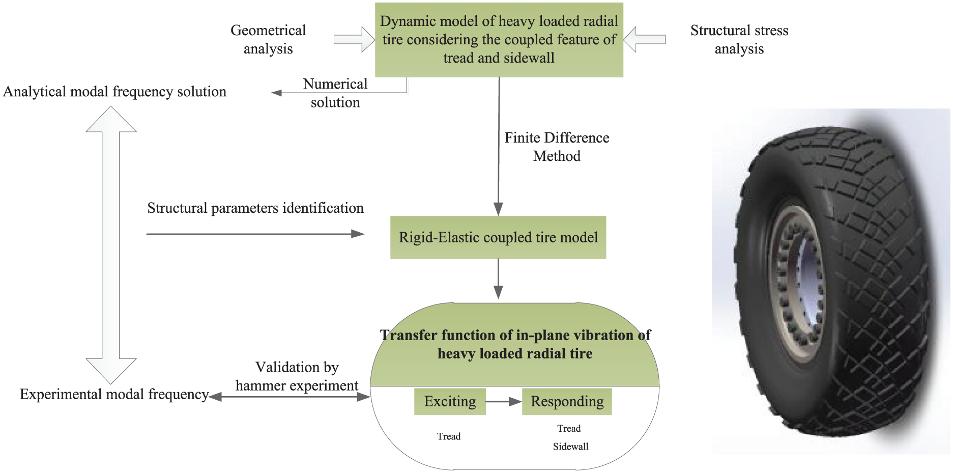
The scheme of the research paper.
In-plane rigid–elastic tire model
The in-plane rigid–elastic tire model is proposed and derived based on the modified flexible beam on elastic foundation considering. The coupled feature of tread and sidewall is taken into consideration. The scheme of the in-plane rigid–elastic tire model is shown in Figure 9.
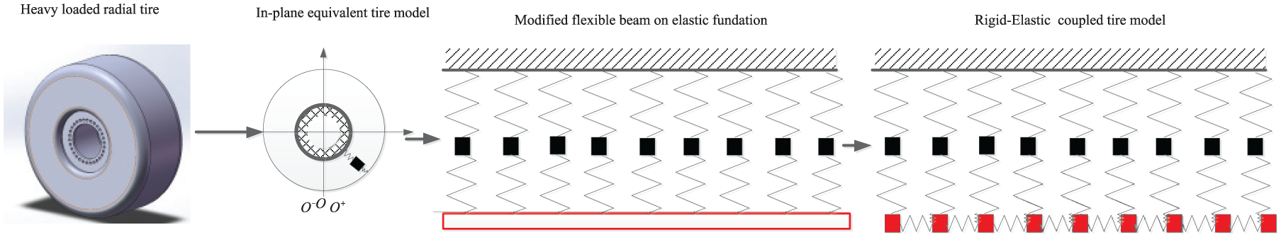
The scheme of the in-plane rigid–elastic tire model.
In-plane modified flexible beam on elastic foundation tire model
The modified flexible beam on elastic foundation tire model is proposed. Bending deformation of tread beam is the main deformation in the low-frequency vibration, ignoring shear deformation and the influence of moment of inertia of cross section around the neutral axis. The modified in-plane tire model consists with three critical sections: tread simulated as Euler beam, sidewall simulated as the two-sectional radial stiffness, and the inertia force and inflation feature simulated as the axis force of the Euler beam, shown in Figure 10.

Coupled model of tread and sidewall with rim fixed.
Equation of force balance 10 of the tread micro-segment is shown in Figure 11


Force analysis of micro-section of tread beam.
Equation of moment balance 10 in Figure 11

Bending moment

where
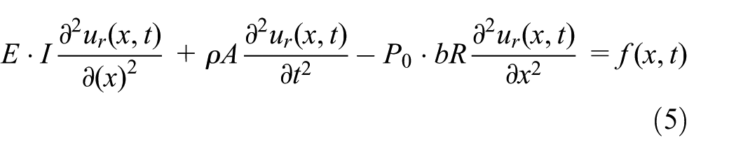
The dynamic equation of tread is derived as equations (1)–(3)
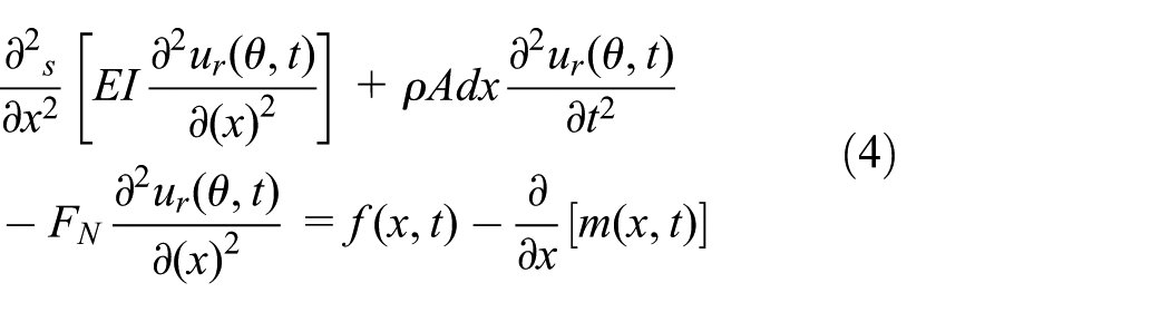
where
Simplification
where E is the elasticity modulus; I is the inertia moment of cross section,
Simplification

Coupled dynamics of tread and sidewall with rim fixed is derived by adding the sidewall simulated as two-sectional radial stiffness and the inertia force given below


where equation (7a) is the bending vibration of tread and equation (7b) is the radial vibration of distributed sidewall segment.
In-plane rigid–elastic-coupled tire model
The in-plane rigid–elastic-coupled tire model is referred as that flexible tread is discrete with finite difference method into N segments, while the sidewall segment is corresponding to the distributed tread segment shown in Figure 12 and connected with tread segment by spring.

Finite segment of tread and sidewall.
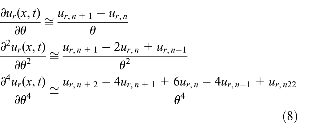
The difference form of the first order, second order, and fourth order is referred as 18
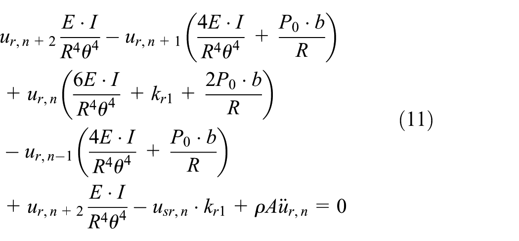
The in-plane modified flexible beam on elastic foundation of heavy-loaded radial tire is transformed


Namely

The equivalent parameters—
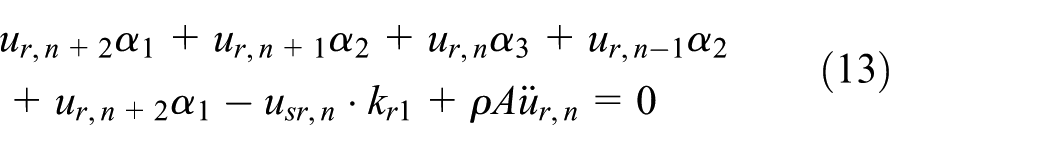
Namely

where

The proportional damping

The second-order ordinary differential equation with freedom of 2 N*2 N is derived, and the three equivalent stiffness parameters—
Known geometrical and structural parameters of GL073A tire.

Under-identified geometrical and structural parameters of GL073A tire.

Structural parameters identification
The backward parameters identification based on the experimental modal parameters is proposed to identify the unknown structural parameters, and genetic algorithm (GA) 19 is utilized as the identification tool, which is famous for global optimization dealing with complex system problems.
As a well-established optimization tool, the description of optimization theory is presented in brief. GA is based on natural selection and genetic theory and combines the survival of fittest rules and the exchanging mechanism of random chromosome within the group, and the scheme of structural parameters identification by GA is shown in Figure 13.
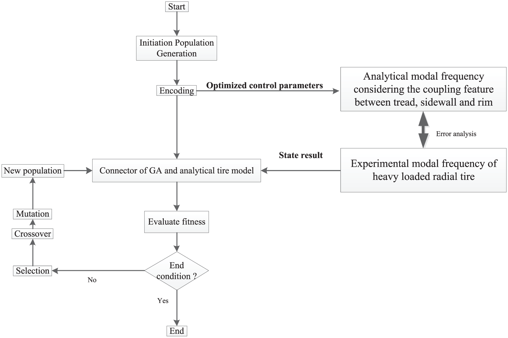
The scheme of structural parameters identification by GA.
Experimental modal parameters
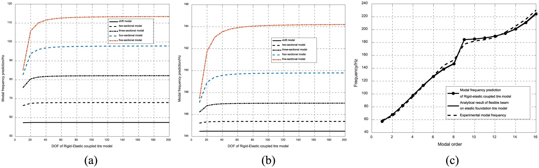
Taking the structural feature of the heavy-loaded radial tire into consideration, the modified modal analysis method considering the coupled characteristic of tread, sidewall, and rim is proposed and implemented, which is shown in Figure 14(a), including tire support device, force hammer and charge amplifier, data test system, and PC computer. The PCB acceleration sensor is pasted, respectively, in the tire tread, sidewall, and rim, and the experimental modal test is implemented through incentive methods along the radial tire tread, which is divided into 34 sections (Figure 14(b)).
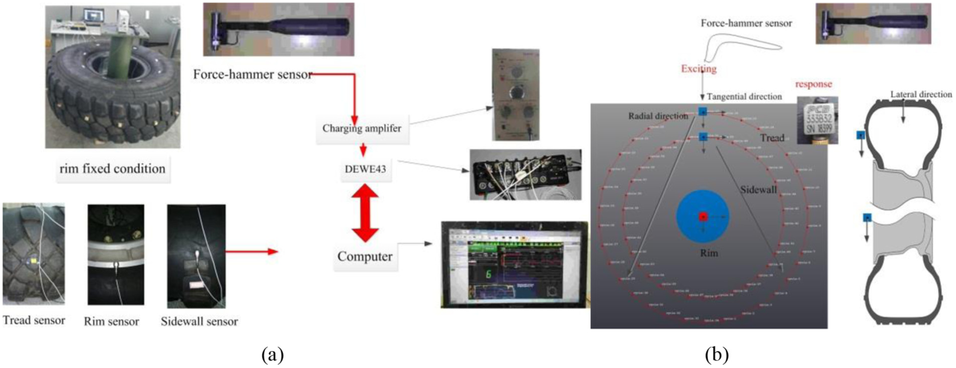
System configuration of experimental modal analysis: (a) hardware equipment of the modal test and (b) incentive method.
The input force is measured by the B&K force hammer transducer, and the signal is conditioned by the charging amplifier. The excited force and the responding acceleration are gathered by DE-43 data collector, and dynamic signal analyzer then computes the desired transfer function.
The transfer function of tread radial response–tread radial excitation, sidewall radial response–tread radial excitation, and rim radial response–tread radial excitation is summed up, and least squares complex exponential (LSCE) method 20 is used to estimate the frequency (Appendix 1), damping (Appendix 1), participation factor, and modal shape (Appendices 2 and 3). In order to validate the orthogonal modal vectors, MAC between each order modal value is computed in Figure 15, compared with that of coupled modal test of tread and rim (Figure 6(b)).
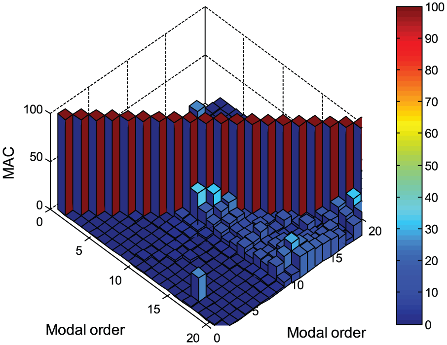
MAC of coupling modal for tread, sidewall, and rim (three-dimensional (3D) view).
MAC value of coupled modal analysis of tread, sidewall, and rim are less than 0.2 (Figure 15), compared with the MAC value of only coupled modal analysis of tread and rim, validating the experimental modal vectors being orthogonal, implying the in-plane experimental modal analysis considering the coupled feature of tread, sidewall, and rim is effective to character the vibration of frequency band within 300 Hz.
Analytical modal resonant frequency
The coupled equation of heavy-loaded radial tire is solved by the modal expansion method, and the partial difference equations are transformed into the time domain and space domain. Assume the free vibration mode in the sinusoidal series as follows

The coupled dynamics of heavy-loaded radial tire are referred as

Namely

Simplifying

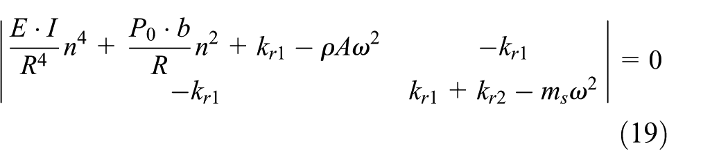
The analytical modal frequency is obtained as
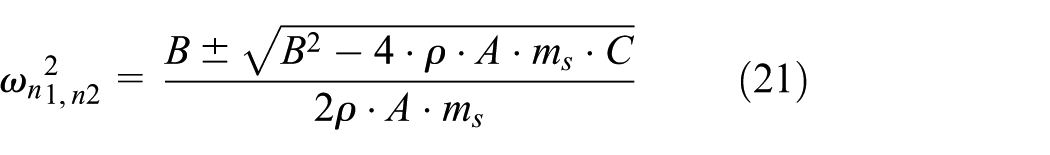
where
Implement of parameters identification by GA
The modal frequency of three-sectional, four-sectional, five-sectional, and six-sectional shape is selected, and to simplify the computation process, the two variables are chosen as the standard function, which are referred as equations (22) and (23)

The error of computed frequency and the experimental frequency is chosen as the object function, referred as equation (24)

The parameters of GA are initialized as population size: 20, generations: 300, generation gap: 0.9, crossover rate: 0.7, and mutation rate: 0.1.
The object value and structural parameters of the parameter identification are shown in Figure 16, and the identified result is shown in Table 3.

Optimization procedure: (a) object value, (b) bending stiffness
Identified result of GA.

GA: genetic algorithm.
Optimization procedure implies that (1) the object value is close to the steady point when the optimization procedure proceeds to 100 generations, which is convergent; (2) the under-identified structural parameters, including bending stiffness
Modal frequency prediction
In order to validate the reality of the identified structural parameters, the analytical modal frequency is predicted and compared with the experimental modal frequency, which is shown in Figure 17.

Analytical modal frequency based on the identified structural parameters.
The compared result implies that (1) the prediction result of analytical heavy-loaded radial tire fits the experimental result, and the error is limited within 5% shown in Figure 23; (2) the in-plane vibration character can be featured as harmonic characteristic seen from the modal shape (Appendices 2 and 3). The modal shape is referred as the same-direction vibration of tread and sidewall within the frequency band of 0–180 Hz; while within the frequency band of 180–300 Hz, the modal shape is featured as the opposite-direction vibration of tread and sidewall. The different coupled vibration characteristics of tread and sidewall can be explained as that the structural and operative feature: overloading inflation pressure, heavier load, larger flat ratio, and larger mass ratio, makes the resonant wavelength longer and reduces the resonant frequency compared with other kinds of tire, such as passenger car tire and truck tire.
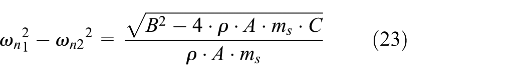
To validate the modal frequency prediction of rigid–elastic-coupled tire model, the influence on the modal frequency of different N is explored and compared as shown in Figure 18. The modal frequency of same-direction vibration shape is shown in Figure 18(a), while modal frequency of opposite-direction vibration shape is shown in Figure 18(b). The result implies that as the degree of freedom (DOF) increases, the modal frequency approaches the steady value shown in Figure 18(a) and (b), implying the rigid–elastic-coupled tire modal is convergent. Modal frequency of in-plane rigid–elastic-coupled tire model is predicted with DOF N = 100 compared with the experimental modal frequency and analytical modal frequency of flexible beam on elastic foundation tire model in Figure 18(c). The compared result is presented that the rigid–elastic-coupled tire model can achieve high-precision modal prediction with DOF N = 100, and the prediction error is limited within 5%.
Influence analysis of different DOFs: (a) same-direction vibration shape, (b) opposite-direction vibration shape, and (c) DOF N = 100.
Transfer function of in-plane rigid–elastic-coupled tire model
Description of hammer test
By means of measuring the response of the heavy-loaded radial tire, caused by a hammer, a frequency transfer function with the rim-fixed condition can be obtained, and the scheme of hammer test is shown in Figure 19. Three exciting points exist along the tread and adjoining interval is 90° as shown in Figure 19(b). Exciting force is measured by the hammer sensor of B&K, and the vibration response is measured by the acceleration sensor of PCB.
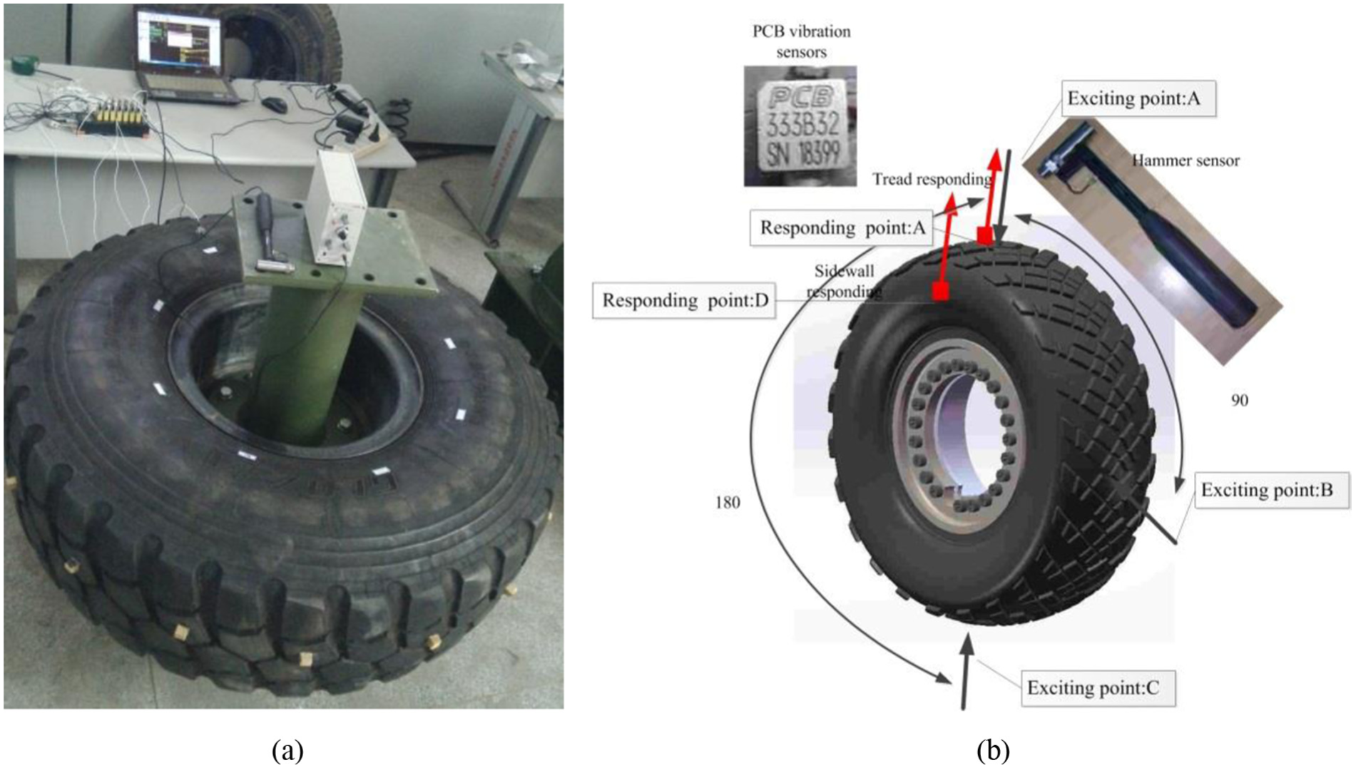
Transfer function of hammer test: (a) rim-fixed condition and (b) hammer test.
In order to validate the vibration transfer function, the vibration responses of tread and sidewall are gathered by the high-speed data acquiring equipment of DEWE-43. The transfer function of tread–tread and tread–sidewall can be calculated.
The tread is excited at the tread points: A, B, and C, respectively, by hammer sensor, and vibration responses of points A and D are gathered, respectively. Six transfer functions are gained by hammer test to validate the analyzing capacity of transfer function.
Analytical transfer function
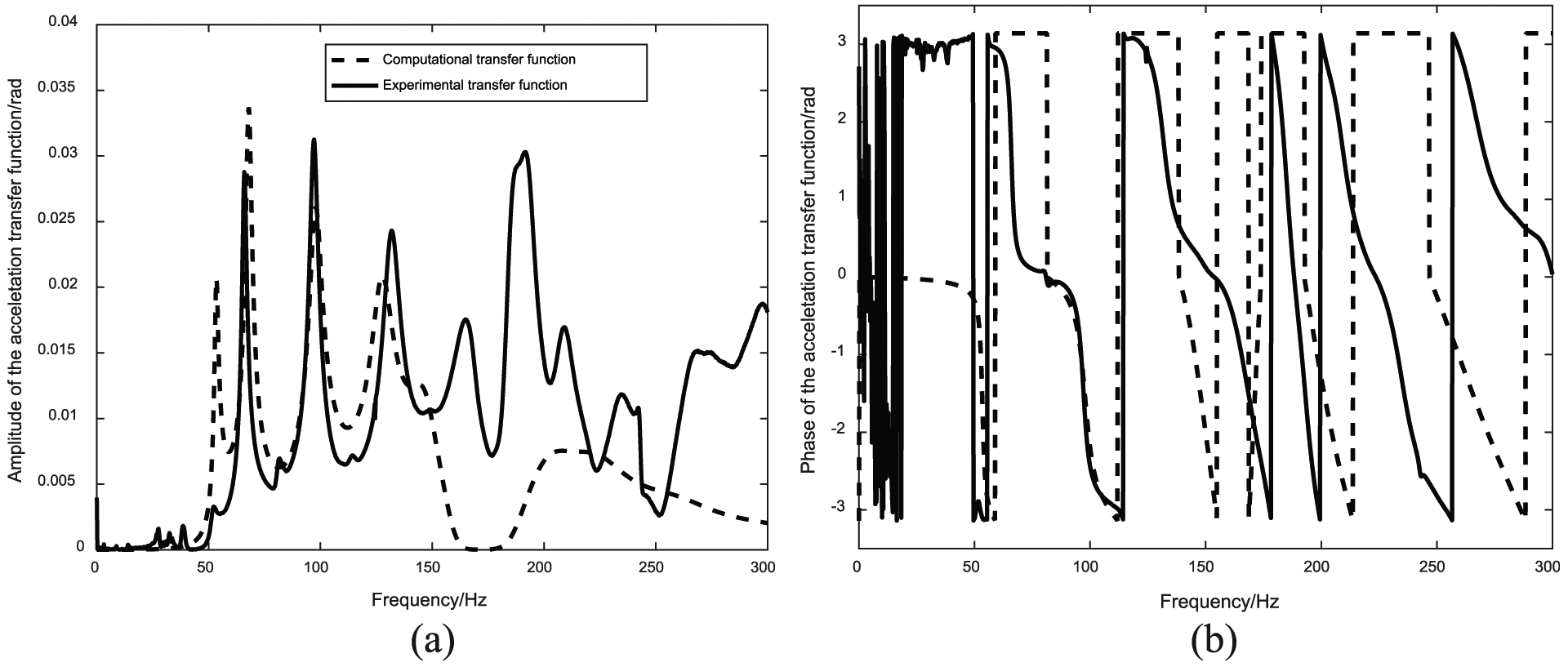
The analytical transfer function of in-plane rigid–elastic-coupled tire model is simulated and compared with the experimental transfer function by hammer test. The transfer function of tread exciting and tread responding is presented in Figures 20–22, while the transfer function of tread exciting and sidewall responding is presented in Figures 23–25.

Tread exciting: A–tread responding: A: (a) amplitude of the transfer function and (b) phase of the transfer function.

Tread exciting: B–tread responding: A: (a) amplitude of the transfer function and (b) phase of the transfer function.

Tread exciting: C–tread responding: A: (a) amplitude of the transfer function and (b) phase of the transfer function.

Tread exciting: A–sidewall responding: D: (a) amplitude of the transfer function and (b) phase of the transfer function.

Tread exciting: B–sidewall responding: D: (a) amplitude of the transfer function and (b) phase of the transfer function.
Tread exciting: C–sidewall responding: D: (a) amplitude of the transfer function and (b) phase of the transfer function.
The compared results imply the following:
The analytical transfer function is compared with the experimental transfer function within 300 Hz, implying that the in-plane rigid–elastic-coupled tire model can character the vibration feature between the tread and sidewall;
The coupled feature of the tread and sidewall makes the transfer function into section shown in Figures 20–25, while the frequency band of 0–180 Hz is referred as the same-direction shape and the frequency band of 180–300 Hz is referred as the opposite-direction shape, which agree with the result of experimental modal analysis in “Appendices 1–3”;
The resonant frequencies of the analytical transfer function fit well with that of the experimental transfer function, but the amplitude of analytical transfer function is larger than that of the experimental transfer function at the shift modal frequency of same-direction modal shape: 55.57 Hz, while the amplitude of analytical transfer function is larger than that of the experimental transfer function at the shift modal frequency of opposite-direction modal shape: 179.076 Hz.
The reason is explained that the mass of sidewall is distributed along the tire radial direction and of anisotropic sectional area, while the lumped mass is taken into the in-plane rigid–elastic-coupled tire model. The in-plane rigid–elastic-coupled tire model presented in the article overestimates the inertial force, and the vibration characteristic of the shift modal shape is dependent on the stiffness and mass. So, the mass of sidewall should be modified to increase precision.
Conclusion
The in-plane vibration transfer function of heavy-loaded radial tire based on the in-plane rigid–elastic-coupled model is researched and validated by experiment, including:
The in-plane vibration modal test and analysis with the coupled feature of tread and sidewall is proposed and implemented;
The in-plane rigid–elastic-coupled tire model is derived, and the backward structural parameter identification is validated with the experimental result;
The modal frequency prediction and transfer function of in-plane rigid–elastic-coupled tire model is presented and compared with the experimental result.
The main results are given as follows:
The in-plane vibration of heavy-loaded radial tire can be referred as the same-direction modal shape within 0–180 Hz; while within the frequency band of 180–300 Hz, the in-plane vibration should be feature as the opposite-direction modal shape. The experimental modal test and analysis considering the coupled feature of tread, sidewall, and rim reveal the vibration characteristic of heavy-loaded radial tire and lay the foundation of the theoretical analysis;
The in-plane rigid–elastic-coupled tire model considering the coupled feature of tread and sidewall is derived based on the modified flexible beam on elastic foundation. The stiffness matrix based on the three parameters—
The backward parameter identification based on the experimental modal parameters can achieve the prediction of high-order modal frequency, and the error is limited within 5% compared with the experimental result;
The analytical transfer function of in-plane rigid–elastic-coupled tire model is derived and validated by the experimental transfer function of hammer test. The compared result implies that the rigid–elastic-coupled tire model can character the in-plane vibration feature of heavy-loaded radial tire within 300 Hz.
Footnotes
Appendix 1
Result of experimental modal analysis under the normal inflation pressure.

| Modal order | Inflation pressure: 0.8 MPa |
Remark | ||
|---|---|---|---|---|
| Frequency | Damping (%) | Modal shape | ||
| 1 | 55.576 | 1.92 | Shift modal | Same-direction vibration shape of tread and sidewall |
| 2 | 65.951 | 1.63 | Two sections | |
| 3 | 81.010 | 1.79 | Three sections | |
| 4 | 97.044 | 2.02 | Four sections | |
| 5 | 114.020 | 2.42 | Five sections | |
| 6 | 131.591 | 2.91 | Six sections | |
| 7 | 149.186 | 3.59 | Seven sections | |
| 8 | 165.783 | 3.76 | Eight sections | |
| 9 | 179.076 | 2.13 | Shift modals | Opposite-direction vibration shape of tread and sidewall |
| 10 | 184.656 | 2.15 | Two sections | |
| 11 | 188.144 | 1.89 | Three sections | |
| 12 | 192.928 | 1.96 | Four sections | |
| 13 | 199.921 | 2.28 | Five sections | |
| 14 | 209.131 | 2.45 | Six sections | |
| 15 | 220.552 | 2.54 | Seven sections | |
| 16 | 234.033 | 2.72 | Eight sections | |
| 17 | 250.186 | 2.82 | Nine sections | |
| 18 | 266.898 | 3.07 | Ten sections | |
Appendix 2
Appendix 3
Handling Editor: Sang-Wook Kang
Declaration of conflicting interests
The author(s) declared no potential conflicts of interest with respect to the research, authorship, and/or publication of this article.
Funding
The author(s) received no financial support for the research, authorship, and/or publication of this article.