
Abstract
This article presents an omnidirectional mobile platform with six mecanum wheels, which provide better carrying capacity than traditional four-wheel platform. Omnidirectional mobile platform with six mecanum wheels can withstand heavier load than the omnidirectional mobile platform with four mecanum wheels, which was used to transport large equipments used in marine and aerospace. Due to the small size, omnidirectional mobile platform with six mecanum wheels move more flexibly and reach desired position and pose easier in narrow workspace, compared with omnidirectional mobile platform with eight mecanum wheels whose disadvantage of large size offsets the advantage of zero turning radius. The kinematic model of the omnidirectional mobile platform with six mecanum wheel is established and verified through four kinds of motion state by the simulation (the omnidirectional mobile platform with six mecanum wheels moving along the Z axis, the X axis, the direction of which angle between positive X is 45°, and the omnidirectional mobile platform with six mecanum wheels rotating around the geometric center). The states of one wheel in failure have been analyzed in this article, taking into account the research levels of omnidirectional mobile platform with six mecanum wheels in the presence. The motion features of the platform with six mecanum wheels and four mecanum wheels are analyzed when certain wheels are locked-up or followed-up based on the force analysis of the wheels, and it proves that the platform with six mecanum wheels moves more stable than the platform with four mecanum wheels. In the presence of wheel failure, the platform still can move to the target location with gesture, due to its redundancy. This study contributes to the research of omnidirectional mobile platform with normal or failure mecanum wheels.
Keywords
Introduction
Autonomous mobile platforms were rapidly developing in last 50 years. It can be categorized into three types: vehicles equipped with wheels similar to the generic automobile type, vehicles with two parallel wheels and one caster wheel (unicycle-type), and vehicles with mecanum wheels.1–3 The omnidirectional mobile platforms have three freedoms (forward/backward, left/right, and turning on the spot) and can move along any direction without changing position. Omnidirectional mobile platform overcome the barriers, while traditional mobile platform could not move transversely and spin on the spot. There are distinct advantages in many situations because of the flexible movement of omnidirectional mobile platform with mecanum wheels. Zero radius of rotation can help the mobile platform move through the narrow spaces with obstacles and obtain high efficiency. The omnidirectional mobile platforms are already widely used for surveillance, transportation, aerospace, and marine. 4 The omnidirectional mobile mechanism researches are mainly concentrated in four-mecanum-wheel omnidirectional mobile platform.
Currently, the heavy-load omnidirectional mobile platform with mecanum in industry mainly used mobile platforms with four mecanum wheels or eight mecanum wheels. However, as increase in size and weight of the aviation products, petrochemical products and electric power products, four-wheel omnidirectional mobile platform gradually has not match under overload. The wheels need more drive torque in heavy loading. Mobile robots usually carry limited power sources. 5 In this case, the mobile platform needs high-voltage power supply which has to install overmuch battery pack and increase the overall size. That design let to negative impact on the economics.
And the mecanum wheel is vulnerable to failure due to its complex structure. The failure situations are solved using several rounds of omnidirectional mobile platform that can response rapidly and reasonably. In particular, actuator failures at the control loop level, which are very common in mobile platforms, may jeopardize the safety of the robot since the position control module reacts on such events with immediate acceleration toward unsafe velocities and forces, which is a risky condition for mobile robots when there are no safety barriers in a hazardous environment. 6 The mobile platform with eight mecanum wheels is too long which cannot show an advantage in limited working space. However, when the omnidirectional mobile platform with four mecanum wheels is intended to be used in hazardous environments or for long-time operations, it is also needed to increase their robustness against possible failures. 7 It is a reasonable choice using synergy drive technology in multiple omnidirectional wheel (mecanum wheel) for heavy loading omnidirectional mobile platform.
This article proposes an omnidirectional mobile platform with six wheels that used synergy drive technology. A kinematics equation has been set up, and then, using ADAMS to complete the kinematics modeling and simulation analysis, some motion features have been obtained. In addition, this article analyzed the motion features of omnidirectional mobile platform with six mecanum wheels (ODMSMWs) when actuators failed. Even in the presence of the wheel failure, the platform can move to the target location with gesture due to its redundancy. The robustness of modeling is indicated through simulation experiment.
Mathematics model of kinematics
Two-dimensional modeling of kinematics
In this work, we consider a mobile platform equipped with six wheels, mounted as pairs on each side of the vehicle and evenly with respect to its center of geometries, moving on planar surface in three degrees of freedom, that is, translation along X and Z axes and rotation about the y. OXY is the coordinate that is connected with the center of geometries. The mecanum wheels are arranged as 1–6 boxes; gradients in the box mean the offset direction of the ground contacting the rollers. The coordinate system Oi, Xi, Yi is connected with omnidirectional wheel hub center Oi; Ri is the wheel center position vector in the platform coordinate system; and ω is the angular velocity of the ODMSMWs which rotates around its geometric center. R is the wheel external radius and l1, l2 is the distance between wheel axis and body center (shown in Figure 1).

Two-dimensional model of ODMSMWs.
Kinematics equation
A precise dynamical modeling is the top priority. Mathematical models can be used to estimate the performance, and this process is highly cost effective, especially due to the minimized development time. 8 To build the kinematics equation of the ODMSMWs, this article propose three hypotheses9–11 about the omnidirectional mobile platform:
ODMSMWs, mecanum wheels, and ground are rigid, the platform motion on the flat ground, ignoring the effects of its own structure and ground deformation in motion.
The friction between wheels and the surface is big enough, the wheel without slippage phenomenon.
Ignore the omnidirectional wheel and omnidirectional chassis in manufacturing error, suppose the contact point of mecanum wheel and ground in the wheel center under face.
The motion of the wheel with angular velocity ω creates axial friction F1 and normal friction F2 between roller and ground. The two forces can be decomposed into axial force Fa and radial force Ft. This makes the mecanum wheels to have the possibility of axial and radial motion.
The core of mecanum wheels robot motion model is to obtain the inverse kinematics equation matrix K. The matrix can put navigation velocity vector map to the four-wheel angular velocity vector. 12
There is a mecanum wheel12,13 in Figure 2. The angle between roller axis and central wheel axis could have any value, but in the case of conventional wheels, it is 45°; the left-hand α = 45° and the right-hand α = −45°, where α is the offset angle of the rollers of the mecanum wheels; ωi denotes the rotational velocity of the ith wheel. 14 The wheels have sideslip phenomenon due to the existence of the roller. Velocity of side-slip 15 is vg; set the wheels xcn axis direction of the speed and the speeds along the direction of the zcn are vxn, vzn


Thus


Movement structure of ith wheel.
The body velocities6,16 are vx and vz (clockwise =−, counter-clockwise =+). Among them, the values of Xoci and Zoci are also represented: left front wheel: i = 1, left-hand α = 45°, Xoc1 = −l2, and Zoc1 = l1; right front wheel: i = 2, right-hand α = −45°, Xoc2 = l2, and Zoc2 = l1; left middle wheel: i = 3, left-hand α = 45°, Xoc3 = −l2, and Zoc3 = 0; right middle wheel: i = 4, right-hand α = −45°, Xoc4 = l2, Zoc4 = 0; left rear wheel: i = 5, right-hand α = −45°, Xoc5 = −l2, Zoc5 = −l1; and right rear wheel: i = 6, left-hand α = 45°, Xoc6 = l2, Zoc6 = −l1, we finally derive the inverse kinematics of the platform as follows:

The Jacobian matrix of the ODMSMWs is a full column rank which meets the condition of omnidirectional movement, which shows that the ODMSMWs can move along X-coordinate axis, Z coordinate axis, and rotate around Y coordinate axis.
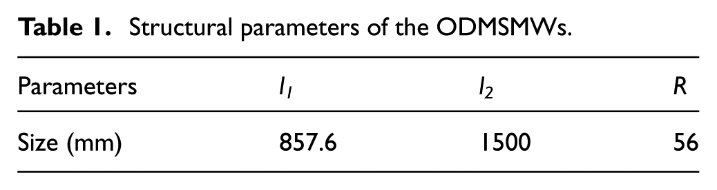
Combining with the characteristics of its load determines the ODMSMWs’ determined structural parameters (shown in Table 1).
Structural parameters of the ODMSMWs.
A common simulation tool used for automotive applications is Automated Dynamic Analysis of Mechanical Systems (ADAMS). 17 However, it is often difficult to obtain all the data necessary to define and execute the computational model. In such cases, the model is often simplified. For this case, a simple modeling method is needed for vehicle analysis. 18 ODMSMWs of three-dimensional model have been built based on the precision requirement, and this study simplified the mechanical structure, omitted the parts which had nothing to do with sport. As this article considers mainly the kinematics of mecanum system during the ODMSMWs kinematics’ simulation, I regard the platform body as a whole part and omit the suspended structure. The rotation of the motor and speed reducer are replaced by drive pair in the software.
The results of simulation and analysis
The simulation of +Z direction
Kinematics simulation of the ODMSMWs moving along the Z axis, given every mecanum wheel, is 180°/s. According to ODMSMWs kinematics equation (6) calculated the speed of platform motion. The result of calculations was shown in Table 2.
The speed of wheels of +Z direction.
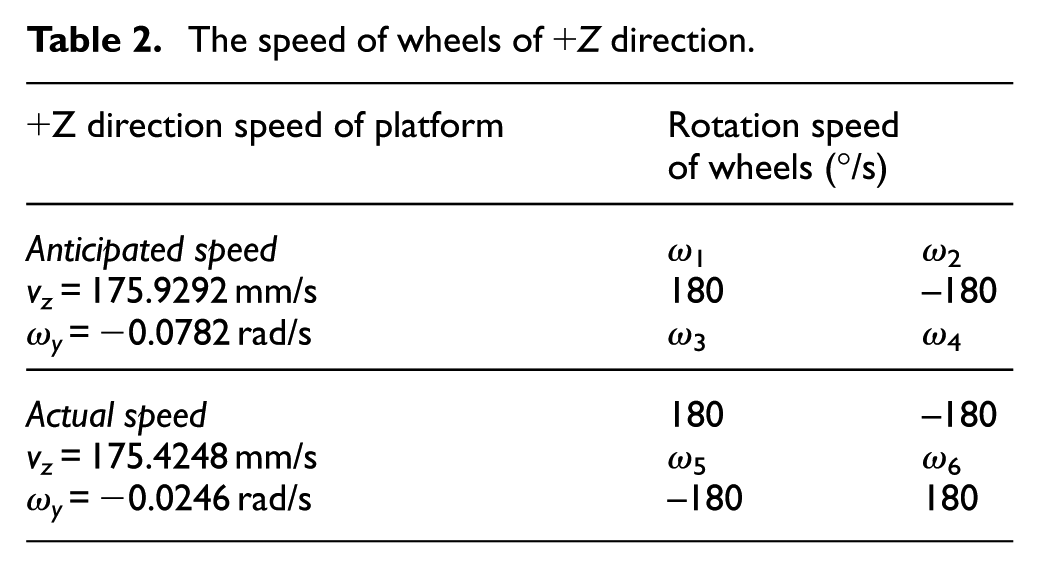
It can be seen in Figure 3 that the speed of movement of platform increases. It is an accelerative process that the movement of platform changes from static state to stable state. The final stable speed of platform is about 175 mm/s that have a very small fluctuation of speed. During the movement, multiple rollers with alternating contact with ground make contact conditions to change constantly, which caused the speed fluctuation in the process of mecanum wheel rotation.

Motion simulation of +Z direction.
The simulation of +X direction
The kinematics simulation of the ODMSMWs moving along the X axis was implemented. The speeds of first wheel, third wheel, and sixth wheel are 180°/s and the speeds of second wheel, fourth wheel, and fifth wheel are −180°/s. According to equation (6), ODMSMWs kinematic equation to calculate the speed of platform motion is shown in Table 3.
The speed of wheels of +X direction.

The speed of the geometric center of the ODMSMWs moving along the X axis is shown in Figure 4. The variation in speed of the geometric center of the ODMSMWs moving along the X axis with time and the speed of the geometric center of the ODMSMWs moving along the Z axis is almost same. The platform began to accelerate from the stationary state. The speed is stabilized at 176 mm/s, which is consistent with the mathematical model that was established. It can be seen from Figures 3 and 4 that the fluctuation of the speed of the omnidirectional mobile platform along the Z direction is greater than that in the X direction, which is caused by the sliding between the rolls and the ground. 19

Motion simulation of +X direction.
The simulation of 45° direction
The kinematic simulation of the ODMSMWs moving along the direction of which 45° down from X was implemented. The speeds of first wheel, third wheel, and sixth wheel are 180°/s. According to equation (6), ODMSMWs kinematic equation to calculate the speed of platform motion is shown in Table 4.
The speed of wheels of 45° direction.
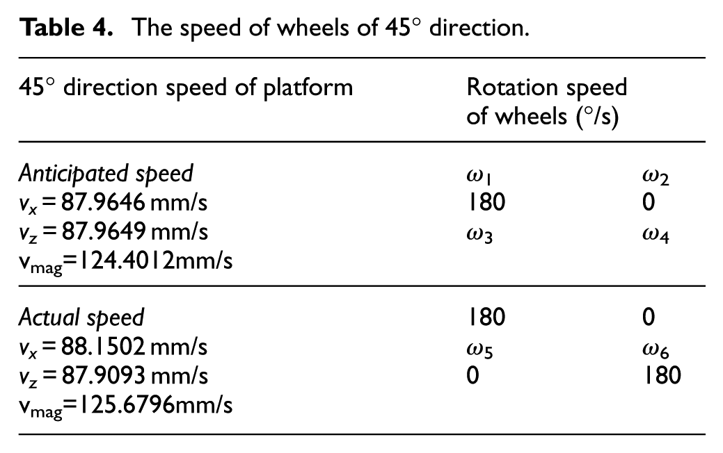
The speed of geometric center of platform that moves along 45° direction is shown in Figure 5. It is easily observed that vx and vz are stable at 88 mm/s; after rising stage, the resultant speed vmag observed is 125 mm/s. It also has a very small fluctuation of speed.
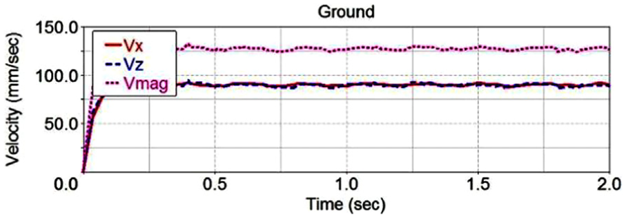
Motion simulation of 45° direction.
The reasons of fluctuation are two. One reason is because the platform moves along the x. The other reason is because the mecanum wheel’s envelope is not a standard cylinder 2 as the rollers being manufactured by approximate ellipse curve.
The simulation of rotational movement
The simulation of rotation around the geometric center
The kinematics simulation of the ODMSMWs rotating around was implemented. The speed of first wheel and fifth wheel is −180°/s and the speed of second wheel and sixth wheel is 180°/s. According to equation (6), ODMSMWs kinematic equation to calculate the speed of platform motion is shown in Table 5.
The speed of wheels rotating around the geometric center.

The rotating angular velocity of ODMSMWs around its geometric center is shown in Figure 6. After the rising stage, the angular velocity arrived at 10°/s, which still has a small fluctuation. Multiple rollers with alternating contact with ground make contact conditions to change constantly, which leads to the speed fluctuation.
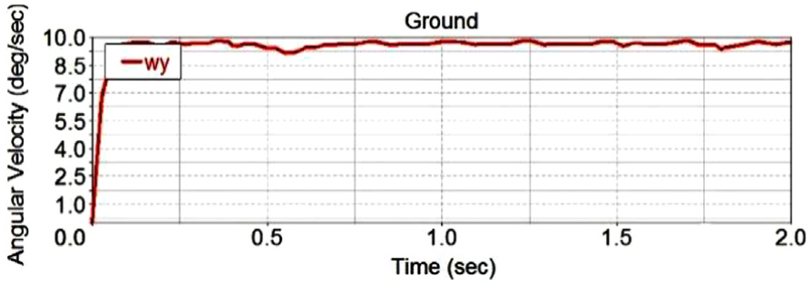
Motion simulation of wheels rotating around the geometric center.
The analysis of rotation around non-geometric center
Figure 7(a) shows that with the motion of the omnidirectional mobile platforms, the speed of wheel 5 is 0°/s and the speeds of other wheels are same (the direction of rotation as shown in Figure 7(a)). At this state, the rotary center of the platform is no longer the geometrical center, but the point that away from the geometrical center point (x, 0, z). The point OB is located in the plane of the centers of first wheel and fifth wheel.

The trajectory of platform rotation around non-geometric center: (a) the trajectory of platform with ω5 = 0, ω1 = −ω2 = ω3 = −ω4 = −ω6 ≠ 0; (b) the trajectory of platform with ω3 = 0, ω1 = −ω2 = −ω4 = ω5 = −ω6 ≠ 0; (c) the trajectory of platform with ω5 = ω6 = 0, ω1 = −ω2 = ω3 = −ω4 ≠ 0; and (d) the trajectory of platform with ω1 = 0, ω2 = −ω3 = ω4 = −ω5 = ω6 ≠ 0.
Figure 7(b) shows that with the motion of the omnidirectional mobile platforms, the speed of wheel 3 is 0°/s and the speeds of other wheels are same (the direction of rotation as shown in Figure 7(b)). The center of turning is on the left in this state.
Figure 7(c) shows that with the motion of the omnidirectional mobile platform, the speed of wheel 5 and wheel 6 is 0°/s and the speeds of other wheels are same (the direction of rotation as shown in Figure 7(c)). The center of turning is in the minus x direction of {A}.
When the speed of first wheel and second wheel is 0°/s and the speed of other wheels is same (the direction of rotation as shown in Figure 7(d)), the center of turning is on the left of the omnidirectional mobile platform. Its trajectory is similar to the state in which wheel 3 has been locked up (shown in Figure 7(d)).
The rotating radius
During turning motions, it becomes important to determine the turn radius. {A} is fixedly connected with the geometrical center of the omnidirectional mobile platform. {B} is fixedly connected with the center of the turning.
The two coordinates are rigid connections. The velocity and the revolving speed3,20 of the mobile platform are defined as follows

P BORG presents the location of the origin of {B} relative to {A}. The cross products can be regarded as operator matrix

Formula (9) can be obtained from formulas (7) and (8)

With referencing the motion of the omnidirectional mobile platform rotating around the geometrical center, we can get a condition as equation (10)

According to equations (9) and (10), the relationship between x and z can be obtained
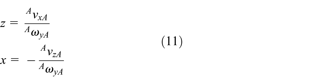
ri is the distance between ith wheel and the center of rotation, and in this case
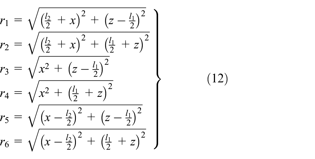

where r is the distance between the geometric center of platform and the center of rotation.
Certain wheels in failure state
The control of mecanum is mostly based on the fact that all the mecanum wheels have same rotation speed. It is known that component failures commonly occur in dynamical systems. 21 The servo motors do not work, which results in the failure of the ODMSMWs. The lock-up of wheel is one mode of failure. A wheel in locked-up means the wheel cannot rotate around its drive shaft but the rollers can rotate freely around its axis owing to the friction with the flat surface. The other mode of failure is follow-up. A wheel follow-up means the wheel cannot be actuated and hence wheels rotate freely around its drive shaft owing to the friction with the flat surface. This chapter analyzed the kinematic of the omnidirectional mobile platforms with six wheels to this state. This article addresses two failure modes: follow-up and locked-up.
Analysis of mecanum wheel
To create a model that gives the force needed for a given movement, the force of the mecanum wheels must be analyzed. The force of mecanum wheeled vehicles is obviously more complex than conventional wheeled vehicles. In the following, an overview will be given on how in this article the force of the ODMSMWs was described.
The structure of mecanum wheel is that free rollers are fixed on the outer ring of the wheel at a 45° angle from the axis of wheel. As the wheels spin, the free rollers contact with the ground. At this moment, the ground will provide a friction force acting on rollers. The angle between friction force and the axis of every wheel is 45°. The friction force would act on a wheel of the vehicle and decompose into two forces: one force parallel to the rotational axis of the wheel and one in the transverse direction. It means the friction force can be decomposed into component X and component Z. The analyses of the force presented in this article are done on the platform from Figure 8.

Force analysis of mecanum wheel.
When the platform moves along +Z, assuming no offset of the centroid of the platform with respect to the attached coordinate system (x, y), there is no rotation of the vehicle if the resulting net torque vanishes; it may easily be shown that the condition for no rotation is


Force Fi acts on the ith wheel. Because the platform is an axisymmetric structure, the relationship between the Fi is
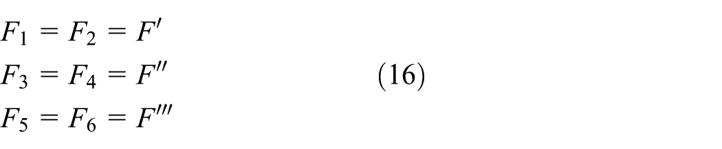
The first wheel and second wheel are left-handed mecanum wheels. The third wheel and fourth wheel are right-handed mecanum wheels. The relationship between the F′ and F″ is

The relationship between the F′, F″, and

Equation (18) can be rewritten as equation (19) after substituting equation (16)

When the platform moves along 45°, F2 = F4 = F5 = 0, and the relationship between Fi is similar to equation (19)
When the platform moves along +X, Fi can be seen as F1 = F2 = F3 = F4 = F5 = F6. When the platform rotates around Y axis, Fi can be seen as F1 = F2 = F5 = F6 and F3 = F4 = 0.
Certain wheels in follow-up
A wheel in follow-up means the wheel cannot be actuated, and hence, wheels rotate freely around its drive shaft owing to the friction with the flat surface. Controlling the platform going forward or backward, if the motor did not transfer torque, the failure of the motor occurs, that is, at this time there is a wheel follow-up, the platform will be subjected to force which displays a degree θ with Z axis and torque. The force and torque of platform are shown in Figure 9.

The force and torque of platform with one wheel follow-up when the platform was controlled to move along +X: (a) first wheel follow-up, (b) third wheel follow-up, and (c) fifth wheel follow-up.
The resultant forces of platform in the above three cases correspond to F+X1, F+X3, and F+X5. The resultant torque of platform in the above three cases corresponds to M+X1, M+X3, and M+X5.When the platform moves along +X, each Fi is equal, setting Fi = F0


The simulation test shows three states: (1) first wheel follow-up, (2) third wheel follow-up, and (3) fifth wheel follow-up (see Figure 13(a)). The trajectory of moving along X axis when a certain wheel follow up as good as normal state. Even if there is a wheel follow-up, the platform still moves basically straight along the X axis. Controlling the platforms going right or left, if a certain wheel follow up, the platform will be subjected to force which displays a degree θ with Z axis and torque. The force and torque of platform are shown in Figure 10.

The force and torque of platform with one wheel follow-up when the platform was controlled to move along +Z: (a) first wheel follow-up, (b) third wheel follow-up, and (c) fifth wheel follow-up.
The resultant forces of platform in the above three cases correspond to F+Z1, F+Z3, and F+Z5. The resultant torque of platform in the above three cases correspond to M+Z1, M+Z3, and M+Z5. When the platform moves along +Z, each Fi is unequal (see equation (30))


The simulation test shows three states: (1) first wheel follow-up, (2) third wheel follow-up, and (3) fifth wheel follow-up (see Figure 13(b)). First wheel follow-up or third wheel follow-up do not have too much impact on the trajectory of moving along Z axis, except fifth wheel follow-up.
Controlling the platform moving along 45°, if a certain wheel follow-up, the platform will be subjected to force which displays a degree θ with Z axis and torque. The force and torque of platform are shown in Figure 11. The simulation test is shown in Figure 13(c).
The force and torque of platform with one wheel follow-up when the platform was controlled to move along 45°: (a) first wheel follow-up, (b) third wheel follow-up, and (c) fifth wheel follow-up.
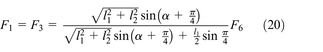
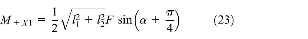
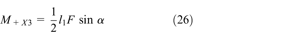
The resultant forces of platform in the above three cases correspond to F45°1, F45°3, and F45°5. The resultant torque of platform in the above three cases corresponds to M45°1, M45°3, and M45°5.When the platform moves along 45°, each Fi is unequal, see equation (20)


The platforms move along 45° perfectly when a certain wheel follow-up. The trajectory is almost the same as the trajectory of none of wheels in failure state. Controlling the platform rotating around Y axis, if a certain wheel follow-up, the platform will be subjected to force which displays a degree θ with Z axis and torque. The force and torque of platform are shown in Figure 12. The simulation test is shown in Figure 13(d).

The force and torque of platform with one wheel follow-up when the platform was controlled to rotate 90° around Y axis: (a) first wheel follow-up and (b) fifth wheel follow-up.

Trajectory of omnidirectional mobile platform with a certain wheel in follow-up: (a) trajectory of moving along +X, (b) trajectory of moving along +Z, (c) trajectory of moving along 45°, and (d) trajectory of rotating 90° around Y axis.
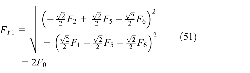
The resultant forces of platform in the above three cases correspond to FY1 and FY5. The resultant torque of platform in the above two cases corresponds to MY1 and MY5.When the platform rotates around Y axis, each Fi is equal


When a certain wheel is in follow-up, the platform was controlled in a normal method. The platform cannot rotate around Y axis; especially, when the influence of the follow-up of first wheel was great (as shown in Figure 13(d)).
To verify the truth that the platform with six mecanum wheels moves more stable than the platform with four mecanum wheels when certain wheels are in failure state, corresponding simulation had been done. The model of omnidirectional mobile platform with four mecanum wheels used in simulation is shown in Figure 14. Determine the structural parameters of omnidirectional mobile platform with four mecanum wheels based on the model of omnidirectional mobile platform with four mecanum wheels (as shown in Table 6).

Two-dimensional model of omnidirectional mobile platform with four mecanum wheels.
Structural parameters of the ODMSMWs.

Note: ODMSMWs: omnidirectional mobile platform with four mecanum wheels.
In that case, first wheel was at follow-up state and the other five wheels were in normal state and the simulation was completed. Except the motion of rotating around the geometric center, the other motion (move along X axis and Z axis, 45°) shown that the trajectory of ODMSMWs is more near to the ideal state (shown in Figure 15(d)).

Trajectory of omnidirectional mobile platform with four mecanum wheels and six wheels when first wheel at follow-up: (a) motion simulation of X direction, (b) motion simulation of Z direction, (c) motion simulation of 45° direction, and (d) motion simulation of wheels rotating around the geometric center.
Certain wheels in locked-up
A wheel in locked-up means the wheel cannot rotate around its drive shaft but the rollers can rotate freely around its axis owing to the friction with the flat surface. The simulation test shows three states: (1) first wheel follow-up, (2) third wheel follow-up, and (3) fifth wheel follow-up (see Figure 16).

Trajectory of omnidirectional mobile platform with a certain wheel been locked-up: (a) trajectory of moving along +X, (b) trajectory of moving along +Z, (c) trajectory of moving along 45°, and (d) trajectory of rotating 90° around Y axis.
When the first wheel was locked up and the other wheels rotate at the same speed and direction, the platform’s trajectory is toward the negative X axis. The offset is great. When wheel 3 was locked up, the trajectory is also toward the negative X axis, but the offset is less. No matter which wheel was locked up, the trajectory has a large gap between the normal state which the platform moving along Z axis.
As wheel 5 was locked in normal state when the platform moves along 45°, it was not simulated. The state at which the first wheel was locked up gives better result than the state at which wheel 3 was locked up.
As wheel 3 was locked in normal state when the platform rotates around Y axis, it was not simulated. The state at which fifth wheel was locked up gives better result than the state at which first wheel was locked up. If the platform rotates 360° around Y axis, the radius of the track will be large.
Similar to the previous purposes, to verify the truth that the ODMSMWs moves more stable than the platform with four mecanum wheels when certain wheels are in failure state, corresponding simulation has been done. In that case, first was wheel in locked-up state and the other five wheels were in normal state, and the simulation was completed. Except the motion of moving along the direction of 45°, the other motion (moving along X axis and Z axis and rotating around the geometric center) shows the trajectory of the ODMSMWs more near to ideal state (as shown in Figure 17).

Trajectory of omnidirectional mobile platform with four mecanum wheels and six wheels when first wheel be locked-up: (a) motion simulation of X direction, (b) motion simulation of Z direction, (c) motion simulation of 45° direction, and (d) motion simulation of wheels rotating around the geometric center.
Experimental results
Robotics has been developed rapidly. Many researchers put their attention on the navigation of mobile robots. The most basic technology of navigation is path planning, which finds a safe and efficient way from starting point to target. In recent years, many researches on path planning have focused on local searching in dynamic environments, where the pose and location of the obstacles are unknown or partially unknown. 22 On the other active research frontier, a controller been proposed with suitable structure to guarantee system stability and satisfactory performance.23,24 Mobile robots are nonlinear system. Control system controls the motion of mobile robots based on the velocity and acceleration that are fed back by robots. De Sousa Junior and Hermerly 25 proposed a novel tracking control approach for real-time navigation of a nonholonomic mobile robot; Yuan et al. 26 designed a controller about mobile robots based on neural net algorithm; Watanabe et al. 27 proposed a fuzzy servo system that is described for a system with noises using a stochastic fuzzy control method with some linear dynamic models; Das and Kar 28 proposed a control structure that makes possible the integration of a kinematic controller and an adaptive fuzzy controller for trajectory tracking, which is developed for nonholonomic mobile robots. This article focuses on the mathematical model of the ODMSMWs; so, path planning should be studied further. Because the omnidirectional mobile platforms with six mecanum wheels have redundancy, even if there is a broken wheel, the platform can reach the desired position and posture. The platforms maybe have to detour. To demonstrate that the platform can reach the desired position and posture with a broken wheel, the above-mentioned mobile platform was considered. This article simulated six conditions: first wheel locked-up, third wheel locked-up, fifth wheel locked-up, first wheel follow-up, third wheel follow-up, and fifth wheel follow-up (see Figure 18). The wheels are symmetrically distributed along the X axis, so the other six cases (second wheel locked-up, fourth wheel locked-up, sixth wheel locked-up, second wheel follow-up, fourth wheel follow-up, and sixth wheel follow-up) are the same as the six conditions mentioned above.

The trajectory of reaching the desired position and posture with a broken wheel: (a) fifth wheel locked-up, (b) fifth wheel follow-up, (c) third wheel follow-up, and (d) first wheel follow-up.
Results and conclusion
In order to meet the development trend of large-precision instruments and equipment which were produced bigger and heavier, this article puts forward an omnidirectional mobile platforms with six wheels. And this article sets up the kinematics model of the omnidirectional mobile platforms with six wheels and the kinematic equations.
This study established the model of the omnidirectional mobile platforms with six mecanum wheels in ADAMS. Through the simulation analysis, motion that the platform moving along +X direction, +Z direction, the direction of 45 degrees and rotating around its geometric center had been obtained. Through the simulation, law of motion that the platform moving along +x direction, +z direction, the direction of 45 degrees and turning motion was analysed.
The simulation results are almost same with the result of calculation that verifies the validity of the mathematical model. The research and development of the establishment of the kinematical model solved the key technical issues of the ODMSMWs. The conclusion for the kinematics control and dynamics controlling laid the foundation.
An interesting point for future work is presenting. An approach to the reliable static output feedback controller analysis and synthesis is proposing for the stochastic fazzyaffine systems. 23 And depending on the multitude of the faults, a robust motion control scheme is developed, which achieves any desired configuration within the operational workspace. 6 That properly may have a significant contribution in this field.
Footnotes
Academic Editor: Hamid Reza Karimi
Declaration of conflicting interests
The author(s) declared no potential conflicts of interest with respect to the research, authorship, and/or publication of this article.
Funding
The author(s) disclosed receipt of the following financial support for the research, authorship, and/or publication of this article: This research work was supported by National Natural Science Foundation of China (71401098), National Key Technology Support Program of China (2015BAF10B01), Science and Technology Commission of Shanghai Municipality (15111104002, 15111106302, 16111107802, 16111108202), Shanghai Training and Support Program for University Youth Teachers (ZZSD15050), and Innovation Program of Shanghai Municipal Education Commission (2015Z102800006).