
Abstract
This article presents an efficient tool path generation method for five-axis machining of a difficult machined centrifugal impeller. Geometry of centrifugal impeller is analyzed, and the inherent low efficiency of the machining of difficult machined centrifugal impeller is obtained. The tool path curves which are calculated by the most common iso-parametric method are shown to testify the waste in machining. The new type machining layers are calculated, and the new machining regions are achieved. The new tool path curves in each new machining region are calculated, and they are sparser and triangular. For the inherent low machining efficiency of difficult machined centrifugal impeller, the machining time can be greatly reduced just by the optimizing tool path generation method in this article. Numerical simulation and a real test impeller are presented as the test of the proposed method.
Introduction
Centrifugal impellers are the very important components in petrochemical engineering, ships, aircraft industry, and so on. Facing the double requirements of aerodynamic performance and operation stability, the careful five-axis machining of the centrifugal impeller is obligatory, and more and more becomes a research focus. Chu et al.1,2 proposed a tool path planning method to finish the undevelopable ruled surface, by the five-axis flank milling with developable surface approximation. Lim 3 focused on the impeller which can lead to manufacturing problems, presented as response surface methodology of five-axis machine to achieve the optimization of the rough cutting factors of impeller. Through the methodology, rough cutting time was minimized, cutting parameters were optimized, and the productivity of impellers machined by five-axis machining was increased. Chu et al. 4 focused on the five-axis machining of centrifugal impeller with split blades and proposed an integrated framework of tool path planning. The machining was divided into four production processes: rough machining, blade semi-finish machining, blade finish machining, and hub finish machining. Several computer-aided manufacturing (CAM) functions that enable automatic generation of quality tool paths were provided and a complex centrifugal impeller with split blades was successfully cut. Chaves-Jacob et al. 5 proposed an optimal strategy to finish an impeller blades using five-axis machining. Three different impeller families were presented, the differences of their machining are studied, flank milling and point milling strategies are compared, and the blade finishing strategy was optimized. Fan et al.6,7 presented a rotary contact method for five-axis sculptured surfaces machining. The rotary contact method found the optimal tool positions by rotating the tool backward could generate big machined strip width, and the improved rotary contact method is developed to improve and perfect the rotary contact method. Chu et al.4,8 proposed a novel tool path planning for five-axis flank milling of ruled surfaces and centrifugal impeller with split blades. It provided several CAM functions in support of different issues in the planning, and the result demonstrated the effectiveness of the novel tool path planning. From the above, it can be seen that the study about the five-axis machining of centrifugal impeller has been lasted for many years, and a series of research results are obtained. Despite this, there are so many difficult problems such as machining procedure,4,5 surface quality,6,7 and machining efficiency3,4,8 need to be improved.
Furthermore, due to the high strength to weight ratio, light weight, good fatigue resistance, and excellent resistance to corrosion, the difficult machined materials such as titanium alloys are used in aerospace, automobiles, ships, and aircraft industry increasingly.9,10 However, titanium alloys are difficult to be machined because of its material characteristics such as high chemical activation, low elastic modulus, and poor thermal conductivity. Patwari et al. 11 studied the influence of chip serration frequency on chatter formation during end milling of Ti-6Al-4V; it included the findings of an experimental study on instabilities of the chip formation process and the influence of these instabilities on chatter formation during end milling of Ti-6Al-4V alloy. Huang et al. 12 proposed a milling force vibration analysis in high-speed-milling titanium alloy. The milling force and acceleration signals were obtained from experiment. Different cutting speed varied from 80 to 360 m/min, and the optimum cutting speed was deduced. Abboud et al. 13 presented a finite element–based modeling to reduce the residual stresses under the Ti-6Al-4V finish turning conditions. The modeling found that the machining conditions could generate a favorable compressive residual stress distribution in the machined surface, and it is important to be identified. Huang et al. 14 focused on the flank milling of Ti-6Al-4V and proposed an analytical model of residual stress. The simulation results of this analytical model indicated that more compressive residual stress was shown in the axial direction than that in the feed direction. Yang and Liu 15 proposed the effect of cutting parameters optimization and surface topography analysis for peripheral milling titanium alloy. The quality of the machined surface was obtained in the combined conditions with low feed, high cutting speed, and small radial. In conclusion, although many researchers have studied the machining about the titanium alloy for many years, those studies are still scattered unsystematically. The study about the machining of the titanium alloy needs more in-depth research.
With the increasing demand of the aerodynamic performance, stability, and energy consumption, the centrifugal impeller needs higher mechanical property but lighter weight. In recent years, some researchers have focused on the numerical control machining of some difficult machined material such as titanium alloy centrifugal impeller. Shi et al. 16 proposed a near net shape forming process of a titanium alloy impeller. Two forming schemes with two-die devices were designed to form the titanium impeller precisely, finite element method was used to simulate the forming process of the impeller, and several key factors were studied in detail. Wu et al. 17 presented an integrated forming process for manufacturing Ti-6Al-4V impeller. An integrated forming process was proposed to manufacture a complex-shaped impeller. The hot iso-static pressing mold with the graphite core pre-depositing a Ni coating layer was designed and conducted, and the results showed that the manufactured impeller had a dimensional precision of 0.15 mm. According to the discussion above, as the key components for multiple industries, the titanium alloy centrifugal impeller is increasingly valued. But, for the numerical control machining of the titanium alloy centrifugal impeller, the research studies are particularly scant.
Focusing on the efficiency and accuracy of the five-axis machining of difficult machined centrifugal impeller, this article proposes an efficient tool path generation for five-axis machining of a difficult machined centrifugal impeller, and the efficient tool path generation can greatly reduce the machining time just by the optimizing tool path generation method. Geometry of centrifugal impeller is analyzed, and the three-dimensional ruled blade surface is defined in
Geometry of centrifugal impeller
Centrifugal impeller is the key part of the rotor system in centrifugal compressor which is widely used in the petrochemical engineering, ships, aircraft industry, and so on. The geometric modeling of centrifugal impeller is composed of hub, blades, and split blades. Figure 1 shows the geometric modeling of a centrifugal impeller, and the impeller includes hub, 9 blades, and 9 split blades.

Geometric modeling of centrifugal impeller.
Blades and split blades are the most crucial parts of the centrifugal impeller. Figure 2 shows a ruled blade surface (blade and split blade have the same geometric modeling) which is widely used in various types of centrifugal impeller. In the

Ruled blade surface.
Table 1 shows some primary parameters of the impeller in Figure 1.
Primary parameters of the impeller.

Traditional tool path generation method
Because centrifugal impeller is a rotating part, there are nine channels which are restricted by the hub, blades, and split blades. Figure 3 shows a channel of centrifugal impeller.
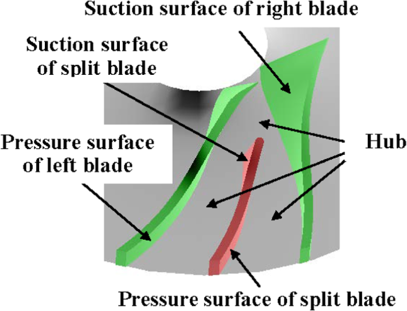
Channel of centrifugal impeller.
The channel is composed by the hub, pressure surface of left blade, suction surface of split blade, pressure surface of split blade, suction surface of right blade. Tool path curves of the channel can finish the machining of the whole centrifugal impeller through the nine rotations of the channel: around Z-axis and 40° each time.
For every space blade surface,

where
Each curve of flow lines can be expressed in the matrix form as


where
Furthermore,
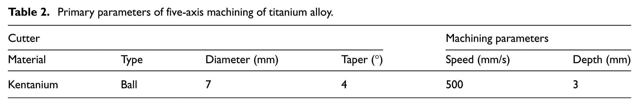
Iso-parametric method is the most common tool path generation method. For the machining of the whole channel, several layers are calculated by the iso-parametric method and be defined as the datum planes. In each datum plane, the iso-parametric tool path curves are generated in the channel. The tool path generation uses the geometric parameters of the impeller shown in Table 1 and the machining parameters shown in Table 2. Then, the machining depth is 3 mm and the maximum axial distance (length of the leading edge) of the impeller is 27.042 mm. So, nine machining layers are calculated from shroud to hub as shown in Figure 4(a). The allowed error is presented as 0.25 mm, and tool path curves are calculated from inlet to outlet in the channel as shown in Figure 4(b).
Primary parameters of five-axis machining of titanium alloy.

Tool path curves using iso-parametric method: (a) common nine machining layers and (b) common tool path curves.
Using iso-parametric tool path generation method, the number of the machining layers is restrained by the geometry near the inlet of the impeller, but each layer must pass through the whole channel. So, near outlet of the impeller, the machining layers are too dense to generate a lot of waste in machining time as shown in Figure 4(a). In each layer, the number of tool path curves is restrained by the geometry near the outlet of the impeller. So, near leading edge of blades and split blades, the tool path curves are too dense to generate a lot of waste in machining time as shown in Figure 4(b).
Focusing on the tool path generation for five-axis finish machining of titanium alloy centrifugal impeller, calculating the new machining layers and new tool path curves, reducing the length of the whole tool path curves, and proposing a novel and efficient tool path generation method are very urgent.
Calculations of the new machining layers and regions
Calculation of the new machining layers
Facing the machining layers which are too dense to generate a lot of waste in machining time as shown in Figure 4(a), the calculation of the new and relatively sparse machining layers are quite eager. Through the analysis of the geometric modeling of centrifugal impeller above, the irregular machining channel is identified as the research target. The irregular channel is composed by the hub and four blade surfaces. From inlet to outlet, the height of the channel is changing from big to small. The maximum is the length of the leading edge of the blade surface, and the minimum is the length of the trailing edge of the blade surface. For the impeller in Figure 1, the two numbers are 27.042 and 6.62 mm which also showed in Table 1: the difference is more than four times between the two numbers.
The new type machining layers to reduce the tool path length can be calculated as the following steps:
Calculate four blade surfaces by the double three-cubed NURBS formula (3) and get
Calculate hub surface by the double three-cubed NURBS formula (1) and get
Define the leading edge of the blade surface
Calculate the vertical distance
Define hub surface
Calculate the intersecting line of
Replace
Define
The flowchart and schematic diagram of calculation of the new machining layers are shown in Figure 5.

New machining layers: (a) flowchart of calculation of the new machining layers and (b) schematic diagram of calculation of the new machining layers.
Calculation of the new machining regions
As shown in Figure 3, the channel is composed by the hub, pressure surface of left blade, suction surface of split blade, pressure surface of split blade, suction surface of right blade. For the simplicity of the later calculations, three machining regions are defined in the channel as shown in Figure 6. From inlet to the leading edge of the split blade in peripheral direction, the region between

New machining regions.
Tool path generation in new machining layers and regions
Using the same cutter, same allowed error, and same iso-parametric method, the tool path curves in new machining layers and regions are calculated. Tool path curves in each layer are very different with the tool path curves in Figure 4. Figure 7 shows four tool path curves in different machining layers. Figure 7(a) shows the tool path curves in
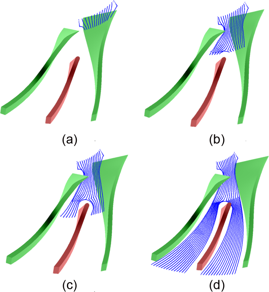
Tool path curves in new machining layers and regions: (a) tool path curves in
For the tool path curves in each iso-parametric machining layer as shown in Figure 4, they have the same length of the curves. The length of the tool path curves in Figure 4(b) is 6581 mm, so the whole length of all tool path curves in all machining layers is 59,229 mm. But, for the tool path curves in each new machining layer and region, they have the different lengths of the curves, and the whole length of all tool path curves is 29,434 mm. Obviously, about 50% of the length of tool path curves is saved (Figure 8).
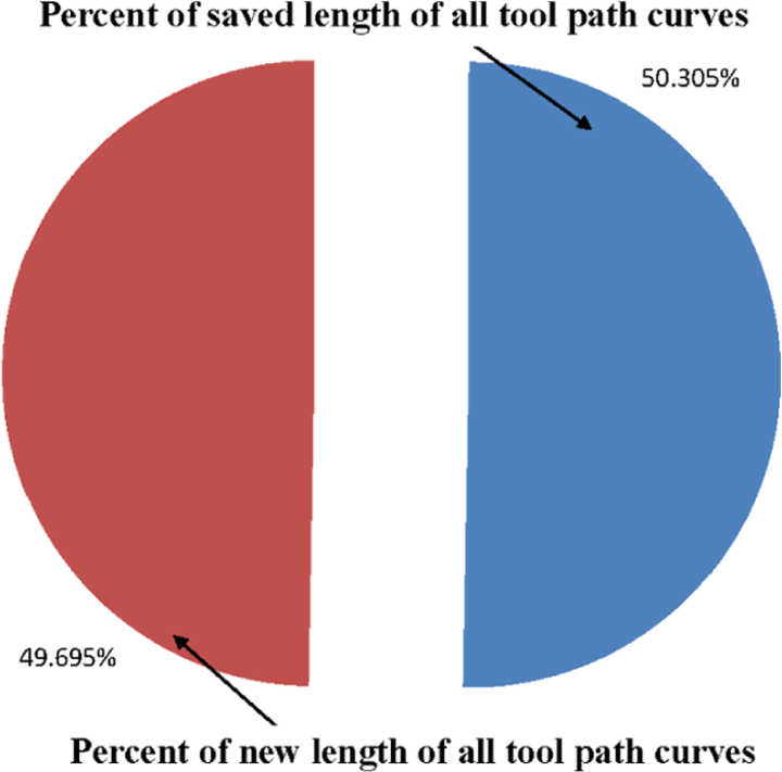
Percent of the new and saved lengths of all tool path curves.
Calculation of the new tool path curves
Through the change of the machining layers and regions, a lot of machining time and cost are saved, facing the tool path curves which are too dense to generate a lot of waste in machining time as shown in Figure 4(b) near leading edge of blades and split blades; the similar research approach can be applied widely.
In each region of every new machining layer, new tool planning is proposed, and the calculation of the new tool path curves can be described as follows:
Define the hub edges of the adjacent blade surfaces as the base curves;
Calculate the tool path interval in the outlet of the region. The relevant parameters are cutter diameter, cutter type, allowed error, geometry of the hub;
Offset two base curves are defined in step 1 to get two tool path curves, the offset direction is from the base curves to the middle of the channel, and the offset distance is the tool path interval calculated in step 2 above;
Define the new tool path curves as the first batch of the tool path curves;
Define the newfound tool path curves as the new base curves and to calculate the other tool path curves by the method in step 3. If the tool path curves are full of the region, go to step 8; otherwise, go to step 6;
If the curves are not intersecting, go to step 5 and continue to offset;
If the curves are intersecting, calculate the intersecting point and take out the parts of the tool path curves from the intersecting point to inlet. Go to step 5 and continue to offset;
Obtain all the tool paths curves.
The flowchart and schematic diagram of calculation of the new tool path curves are shown in Figure 9.
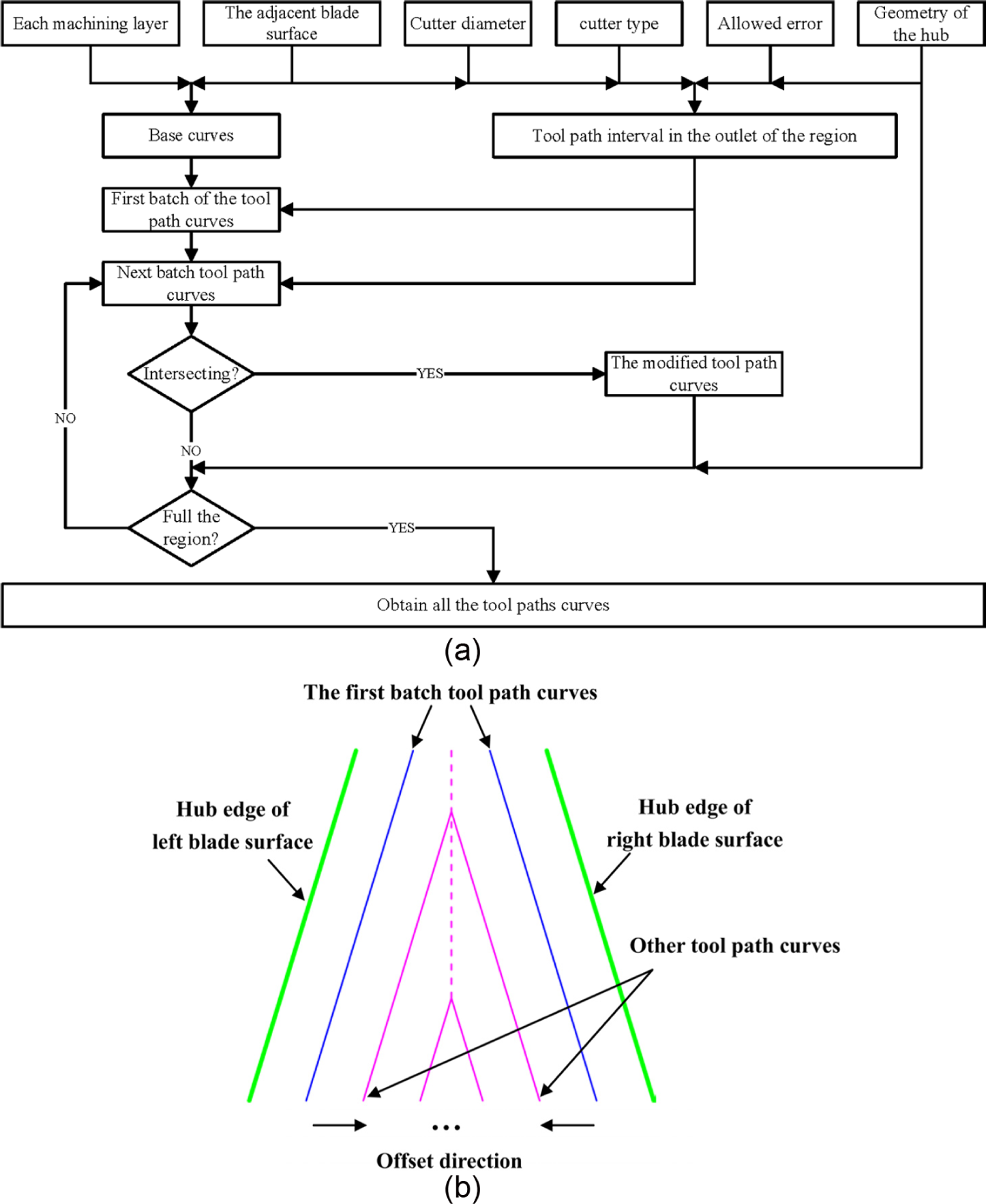
New tool path planning: (a) flowchart of calculation of the new tool path curves and (b) schematic diagram of calculation of the new tool path curves.
For the first batch of the tool path curves, the objective of the machining is to obtain the wanted blade surface. Then, the flank milling algorithm is selected to ensure the high precision of the ruled surface. For the other tool path curves, the objective of the machining is to obtain efficient material removal. Because there is relatively capacious machining space for the tool path curves, the fixed tool orientation and fixed feed at each cutter point are calculated to enhance the instability of machining and improve machining efficiency.
Through the calculations of the new tool path curves and the tool orientation, the different and shorter tool path curves are calculated. The curves in

New tool path curves: (a) new tool path curves in
For the length of the whole tool path curves calculated by the new method, its number is 23,244 mm. That is to say, about 20% of the length of tool path curves is saved further (as shown in Figure 11(a)). Through the optimizing of the tool path generation in two phases, for the whole five-axis machining of titanium alloy centrifugal impeller, 60% of the length of tool path curves are saved (as shown in Figure 11(b)).

Percent of the new and saved lengths of the new tool path curves: (a) percent of the new and saved lengths (comparing with the method in section “Calculation of the new tool path curves”) and (b) percent of the new and saved lengths (comparing with the method in sections “Calculations of the new machining layers and regions” and “Calculation of the new tool path curves”).
To sum up, using the efficient tool path generation for five-axis machining of a difficult machined centrifugal impeller above, 60% of the length of tool path curves is saved. For the real machining, because of the restraint of other technological parameters such as feed rate and processing depth, the length of tool path curves is not the unique standard of machining efficiency. But, it is still one of the key parameters to measure machining efficiency. Especially, for the difficult machined parts, the efficient tool path generation method can reduce the machining time just through tool paths planning. That is to say, although there is a gap about 10 times between the machining impeller with titanium alloy and stainless steel, the difference can be greatly reduced by the optimizing tool path generation method in this article.
Machining experiments
Through the calculation and simulation above, an efficient tool path generation for five-axis machining of a titanium alloy centrifugal impeller which 60% of the length of tool path curves and a lot of cost are obtained. At the same time, Cincinnati Milacron H5 horizontal machining center with Acramatic A950MC computer numerical control system is chosen to machine the test impeller.
The test impeller is real machined as shown in Figure 12(a). Figure 12(b) shows distribution of the measured points in the blade surfaces: Each 11 measure points are marked in the shroud and hub edges in the four blade surfaces; and the biggest value of the machining errors in each corresponding position in the shroud and hub edges from leading edge to trailing edges is selected as a machining error. The distribution of the machining errors is displayed by the lines and symbols as shown in Figure 12(c).

The machining experiment: (a) the test impeller, (b) distribution of the measured points, and (c) the machining errors of the blades.
Conclusion
In this article, an efficient tool path generation method for five-axis machining of a difficult machined centrifugal impeller is presented. Through the analysis of the geometry of centrifugal impeller and characteristics of titanium alloy, the inherent low machining efficiency of difficult machined centrifugal impeller is obtained. Facing the shortcoming of the iso-parametric method, the new machining layers are calculated and the machining layers become relatively sparse and 50% of the length of tool path curves is saved; furthermore, three new machining regions are achieved, and the calculation of the tool path curves in each machining region becomes easy and independent. The new tool path generation method in each new machining layer and new region is presented, and 20% of the length of tool path curves is saved further. Just through the optimizing of the tool path generation method, 60% of the length of tool path curves is saved in the whole machining of the difficult machined titanium alloy centrifugal impeller. For the inherent low machining efficiency of difficult machined centrifugal impeller, the machining time can be greatly reduced by the optimizing tool path generation method in this article. Furthermore, this method can be used for the other complex and difficult machined parts widely.
Footnotes
Handling Editor: Xichun Luo
Declaration of conflicting interests
The author(s) declared no potential conflicts of interest with respect to the research, authorship, and/or publication of this article.
Funding
The author(s) disclosed receipt of the following financial support for the research, authorship, and/or publication of this article: The authors acknowledge the financial support provided by the National Nature Science Foundation of China (Grant no. 51236006).