
Abstract
The centrifugal impeller with arbitrary surface blades is a very important component in automobile, ships, and aircraft industry, and it is one of the most difficult parts to process. Focusing on the machining efficiency improvement, combining the geometric advantages of ruled surface and arbitrary surface, and utilizing the efficient and accurate advantages of flank machining and point machining, this article presents a novel and targeted tool-path generation method and algorithm for five-axis flank machining of centrifugal impeller with arbitrary surface blades. In light of specific characters of different surfaces, the analyses of two different impeller blades are proposed first, the more characteristic and complex geometrical structures of the arbitrary blade are achieved. In rough machining, an approximate ruled surface blade is obtained, and a simple channel is achieved; the flank milling of the centrifugal impeller with ruled surface blades is achieved relative to the point milling of the centrifugal impeller with arbitrary surface blades; and the triangle tool path planning method is added in this process to save the machining time and cost collectively. Furthermore, in semi-finish machining, the approximate sub-ruled blade surfaces are calculated, and a new flank milling method of the sub-ruled blade surfaces is achieved; a new solution for tool interference is achieved in this process and the generation of non-interference tool paths becomes easy. Machining experiments of two different impellers are presented as a test of the proposed methods.
Introduction
Comparing with the conventional three-axis machine, five-axis computer numerical controlled (CNC) machines are widely used to automobile, ships, and aircraft industry. Since 2-degrees of freedom were added to the five-axis machine, the tool can be allowed to machine sculpture parts, which usually have complex geometry and are represented by parameters in very difficult conditions. Furthermore, they share the competitive advantages on higher efficiency, more stability, and less cutting error.1–3
The machining target part, which is composed of freeform surfaces, is one of the research focuses and difficult points for five-axis machining. Lee 4 presented a new approach to generate five-axis numerical controlled tool path for sculpture surface machining. Using the non-isoparametric path generation algorithm and a machining strip evaluation method, a shorter tool path was obtained. Jun et al. 5 presented a method to optimize and smooth the tool orientation control for the five-axis machining of the sculpture surface. An optimal tool orientation was found based on the different machining constraints and a global smoothing method, the key point was the investigation of a searching method in the machining configuration space (C-space). Sriyotha et al. 6 proposed a geometrical modeling of a ball-end finish milling for the complex workpieces, such as dies and moulds. The simulation system accurately predicted the surface topography and simulated the surface microfeatures, which are formed by the five-axis milling process. Fallah and Arezoo 7 focused on the compensation of reference surface errors in the machining of freeform features, a new method for manufacturing error-free workpieces was proposed, and the production time and cost were saved. Can and Ünüvar 8 presented a new approach to determine the efficient iso-scallop tool paths of a freeform B-spline parametric surface. In addition, arc-intersect method, 9 iso-conic partitioning method, 10 steepest ascent method, 11 and so on were presented for five-axis machining of the freeform surface.
Centrifugal impeller is a very important component in automobile, ships, aircraft industry, and so on, and it is regarded as one of the most difficult parts to process. So, the researches on the efficiency and precision of the impeller are more and more deep and interdisciplinary. Furthermore, because performance of the centrifugal impeller is directly influenced by the quality of impeller blades, 12 and as the general theory of three-dimensional flow was proposed in 1952, 13 the researches of the five-axis machining of centrifugal impeller focus on two types of impeller blades: ruled surface blade and arbitrary surface blade.
The ruled surface blade is the conventional three-dimensional flow surface and widely used in a variety of industries. It can be regarded as a type of the limited freeform surface. The five-axis machining for the impeller with ruled surface blades has been researched for many years, a lot of researchers have focused on it, and a series of research findings were produced recently. Young et al. 14 focused on the improvement in the material removal rate, and presented a five-axis rough machining method for centrifugal impellers. The tool paths for impeller-like models were generated automatically using a main module, and the lead time of manufacturing was shortened to reduce the total manufacturing cost. Chu et al. 15 proposed a machining accuracy improvement method in five-axis flank milling of ruled surfaces. An off-line tool was provided to improve the machining precision in five-axis flank milling of ruled surfaces by considering the machine tool capability. Gong and Wang 16 proposed a new tool path method of flank milling with the consideration of the constraints for ball-end cutters. The machining error range was reduced by considering two useful constraints; two types of cutters were used to generate tool paths for the same designed surface and constraint surface. Senatore et al. 17 presented an optimizing positioning of the axis of a milling tool on an offset ruled surface by geometric error minimization. In addition, cutting speed, cutting force, and prediction algorithm were also studied in recent years.18,19
The arbitrary surface blade is a new-style three-dimensional flow surface and has been drawing increasing attention. With the demands for improving efficiency and restraining the energy consumption, noise and vibration to a reasonable level, the arbitrary surface blades which can provide exceptional overall performance were increasingly used in marine, energy, aero-space, and turbo-machinery industries. Compared with the ruled surface, the arbitrary surface can be regarded as the true freeform surface. Several years ago, some researchers started to study the five-axis machining of the centrifugal impeller with arbitrary surface blades. Cai and colleagues20,21 proposed a global tool interference detection method for five-axis machining of sculptured surfaces. The minimum distance from the surface to the cutter axis can be directly calculated by an iterative algorithm. Specifically, a new efficient tool path planning was presented for five-axis surface machining with a drum-taper cutter. Wu and Wang 22 proposed an automatic triangulation method for three-dimensional parametric surfaces based on the advancing front method. A robust triangular element formation procedure was established, and a simple but effective convergence-checking scheme was presented. Fan and Xi 23 proposed an algorithm to optimize the tool path generation for numerical controlled machining of sculpture impeller blade surface. Four sub surfaces which can be obtained and more efficiently calculated were achieved on the entire sculpture blade surface; the optimizing algorithm had significantly reduced the machining time and cost through the three-axis machining instead of the five-axis machining.
For the five-axis machining of the different centrifugal impellers, the differences of the studies were obvious: flank machining is the subconscious machining method to machine the impeller with ruled surface blades because of the relatively simple geometric characteristics of the part, and point machining is the natural choice because of the more characteristic and complex geometrical structures of the parts. Wu 24 proposed a new method for the numerical controlled machining of the arbitrary surfaces of fan, compressor, and impeller blades; if the arbitrary surface could be approximated to a ruled surface, the inefficient point milling could be improved. By contrast, Chen et al. 25 focused on the reverse movements of moving axes along five-axis tool paths, and presented removing tool path marks of blade surface by smoothing five-axis point milling cutter paths. A ruled surface was provided and finished by point milling method. Chaves-Jacob et al. 26 proposed an optimal strategy for finishing impeller blades using five-axis machining. Three finishing strategies, that is, pointing milling, flank milling in one path, and flank milling in multi-paths for impeller blades were presented.
As the literatures mentioned above show, flanking machining method which is always used to machine the ruled surface is a more efficient method to remove the material; on the other hand, point machining method which always used to machine the arbitrary surface has the obvious advantage in milling accuracy. Combining the geometric advantages of ruled surface and arbitrary surface, utilizing the efficient and accurate advantages of flank machining and point machining, and proposing a novel and targeted tool-path generation method for five-axis flank milling of centrifugal impeller with arbitrary surface blades is the research goal of this article.
This work proposes a mathematical analysis and comparing method between the impellers with ruled surface blades and the impellers with arbitrary surface blades; more characteristic and complex geometrical structures of the arbitrary blade surface are achieved. An approximate ruled blade is obtained by the confinement of the milling error and the geometrical distinction of the arbitrary blade in rough machining; flank milling is chosen to replace the traditional point milling of the arbitrary blade. A triangle tool path planning method is achieved in this process and a lot of machining time and cost are saved. Several needed sub-ruled surfaces are obtained in semi-finish machining, a new flank milling method of the sub-ruled blade surfaces is achieved, a new solution method of tool interference is achieved, and a simpler algorithm is obtained compared to the conventional solution method of tool interference. A finished machining test impeller is provided to prove the correctness of the novel tool-path generation method for five-axis flank milling of centrifugal impeller with arbitrary surface blades; another test impeller which was just machined through rough machining and semi-finish machining is provided, and the difficulty and the following considerations of this research are presented.
Analyses of two different impeller blades
As the key part of the impeller, the first geometric model of the blade named the impeller meridian plane line is made up of the four boundary curves, which are named leading edge, trailing edge, shroud edge, and hub edge. In the design of an impeller, the shroud edge and the hub edge are defined by the basic geometric data which were given in a cylindrical coordinate system. The leading edge is the line between the start points on the shroud edge and the hub edge, and the trailing edge is the line between their end points. Figure 1 shows the impeller meridian plane line in the
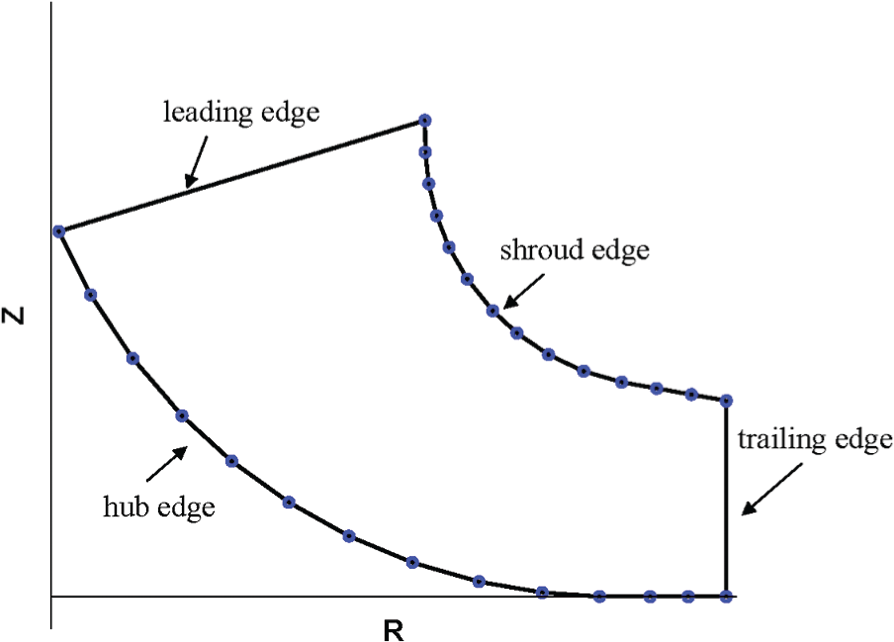
Impeller meridian plane line.
Ruled surface blade is a limited freeform surface. In the cylindrical coordinate system, the twisted shroud edge and hub edge are obtained by adding the θ-axis. Therefore, the ruled surface blade is defined in
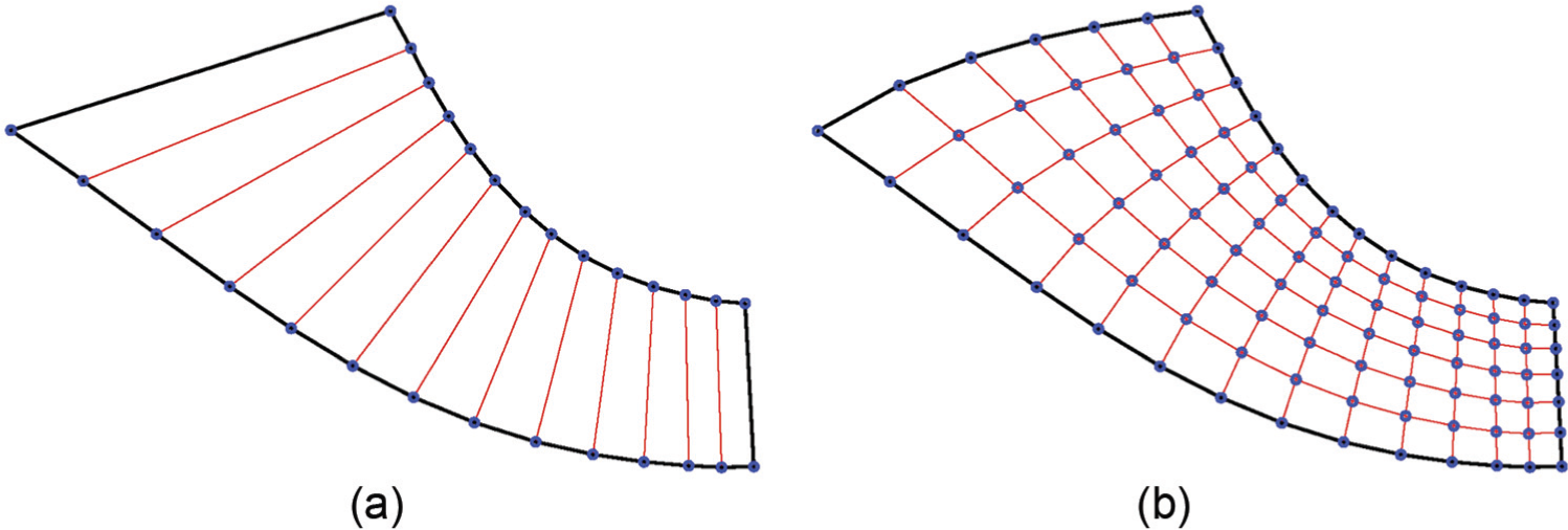
Two different impeller blades: (a) ruled surface blade and (b) arbitrary surface blade.
For the arbitrary surface blade, different space geometrical structures are shown in Figure 2(b). The space points are determined in the leading edge and trailing edge on the arbitrary surface, which means the leading edge and the trailing edge are twisted space curves too. Furthermore, in the region restricted by the four edges, the blade surface is described by a series of space curves rather than a series of lines.
On the other hand, from the view of computational fluid dynamics (CFD), the aerodynamic characteristic of an impeller with the ruled surface blades is merely controlled by the twisted shroud edge and hub edge. Owing to the added control flow lines and control points, more complex flow field and better aerodynamic characteristics can be obtained using the arbitrary surface blades. Figure 3(a) shows the flow lines of the ruled surface blade, and as can be seen the prominent secondary flow vortex is in the middle of the blade; Figure 3(b) shows the flow lines of the arbitrary surface blade; the flow lines are relatively uniform and as there is no prominent secondary flow vortex, the aerodynamic characteristic is naturally better.
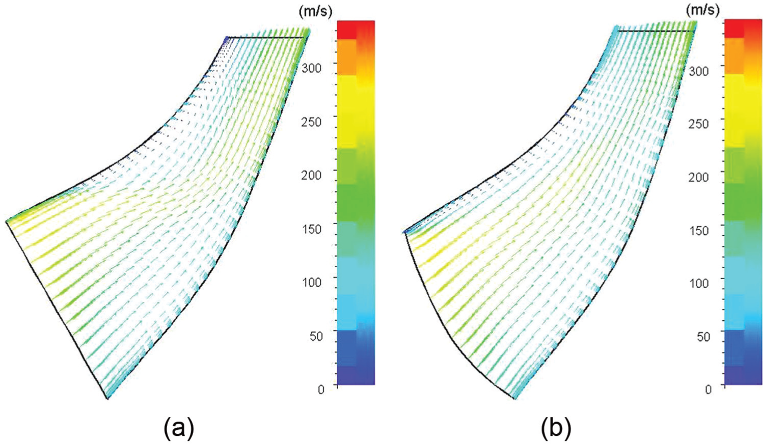
Flow lines of two different impeller blades: (a) flow lines of the ruled surface blade and (b) flow lines of the arbitrary surface blade.
But low machining efficiency is the limiting factor for the popularization and application of the arbitrary surface blades. The common point machining is not the suitable method in the whole processing procedure: it is precise but time-consuming. Flank machining is the best research point of the five-axis machining of the centrifugal impeller with arbitrary surface blades because of its high efficiency.
Different from the surface division of geometry, a controllable surface division method restrained by the ruled surfaces waiting to be processed is proposed. The ruled surfaces waiting to be processed approximate the original arbitrary surface and different forms are calculated in different machining processes.
Tool path generation of rough machining
In the rough machining of the impeller, high efficiency is the research focus: more metal is removed quickly; more time and more machining cost are saved. For the precision of the target surface, it is the research focus in the following finish machining.
Generation of the approximated ruled surface blade
Because of the complex geometrical characteristic of the arbitrary surface blade, tool paths of flank machining are very difficult to be generated. But comparing the ruled surface blade with the arbitrary surface blade, as shown in Figure 2(a) and (b), the similar shroud edge and hub edge are the focuses, which can be considered as the connections of the two types of blades.
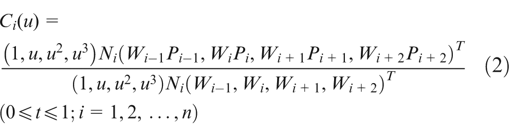
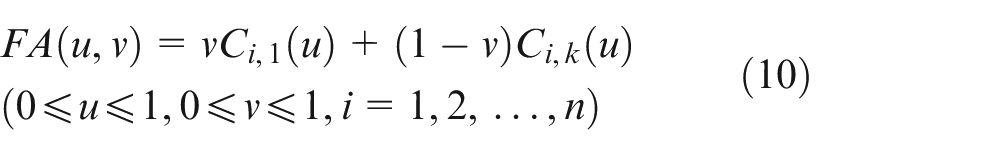
The arbitrary surface blade Ω is defined as a double three cubed non-uniform rational B-splines (NURBS) surface, 23 the matrix form of which is
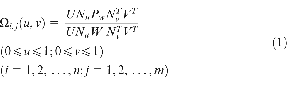
where
For
Let the other curves of flow lines between
As shown in Figure 4, the shroud edges and hub edges of the two blades coincide with each other. The significant difference between the arbitrary blade and the ruled blade is shown in the leading/trailing edges. Most obviously, the leading edge of the arbitrary blade is a space curve, but the leading edge of the ruled blade is a straight line.
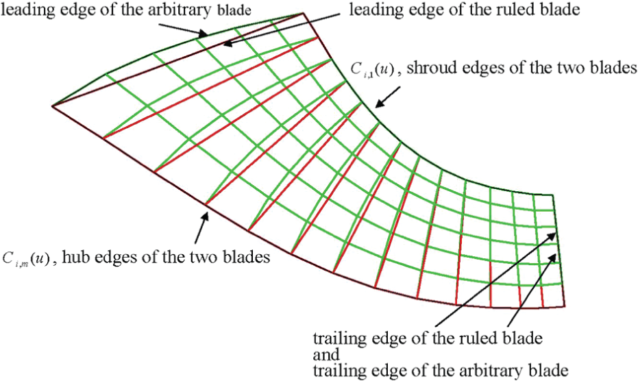
The approximated ruled blade and the arbitrary blade.
The ruled blade with suction surface and pressure surface
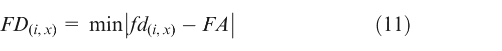
The two different surface blades with the same shroud edge and hub edge are obtained, but the space is obvious between the two blades. In rough machining, the main issue that the researcher must face to is what the arbitrary surface blades must not be cut. Therefore, the distance between the approximated ruled blade and the arbitrary blade must be calculated. From the approximated ruled blade, the arbitrary blade looks like a suction surface, and the tendency is not turned on the whole blade. First,
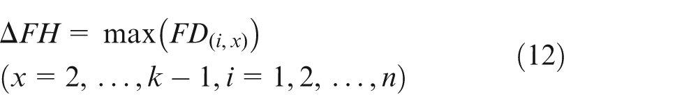
For the whole space between the two blades,
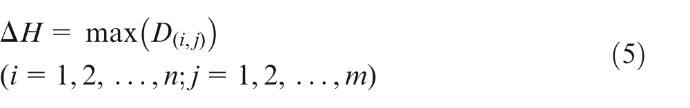
Then, for the rough machining, the real blade with thickness which defined as
The real blade
The real blade B (with thickness).
In conclusion, the approximated ruled blades (blade surface and the blade with thickness) are obtained in sections “Generation of the approximated ruled surface blade” and “The ruled blade with suction surface and pressure surface” above; there are two unique features of the method which are different from the ordinary generation method of the ruled surface in the computer-aided manufacturing (CAM) software. One is that the approximated ruled blades can be obtained strictly by the allowable error; another is that the original blade surface or the approximated ruled blades can be split optionally by every
Through the surface division mentioned above, the original machining channel which constituted the hub and adjacent arbitrary surface blades becomes a relatively simple channel which constituted the hub and adjacent ruled surface blades. Simple algorithm and high efficiency are easy to be achieved in follow-up work.
Tool path generation of rough machining
Generally, the blade surfaces were machined by removing metal material. The machining technique to remove metal material mainly depends on the shape of the space between a blade and the adjacent one. Two most important tool paths can be obtained by calculating the peripheries of the cutter edges that touch the two adjacent blade surfaces. Between them, the removal of the metal material is a time-consuming process.
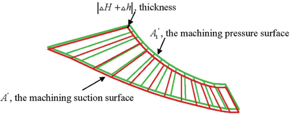
Figure 6(a) shows the conventional isoparametric tool path planning for the channels between the two adjacent blade surfaces. All the tool paths are a series of curves, and they pass through the whole channel from leading edge to trailing edge (
Two different tool path planning methods: (a) isoparametric tool path planning, (b) flowchart of the triangle tool path planning method, and (c) triangle tool path planning.
This research proposes a tool path planning method, which improved by the iso-scallop method, and the advantage is the special tool path arrangement for the channel, which constituted the hub and the approximated ruled surface blades. Similarly, the NURBS channel surface and the two curves on the left and right side are calculated first. The difference appears in the zone between the two sides: a triangular tool path planning.
The entry point of the improved tool path planning is the allowable scallop height.
The tool path interval
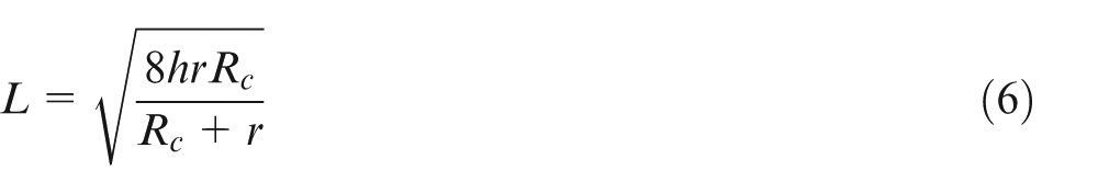
The tool path interval
When
For the target channel surface in this research, there is a minor warp on it.
The improved triangle tool path planning method can be concluded as follows:
Calculate the tool path interval
Calculate the path-line number on the outlet of the channel by the division of the outlet edge of the channel;
Get the two curves on the left and right sides;
Offset the two curves from sides to middle, get a series of curves which overlap each other. The offset distance is
Calculate and get the crossover points of the curves which are obtained in step 4;
Delete the parts from inlet of channel to the crossover points of the crossed curves;
Get the wanted curves of tool paths. The number of the path-line is decided by the tool path interval
Finish the tool path generation through the addition of technological parameters.
The triangle tool path planning method is shown in Figure 6(b), and the tool path planning for the channels between the two adjacent blade surfaces is shown in Figure 6(c).
For a same channel, the different path-line lengths are shown in Figure 7. The graph was finished in a same situation: same cutter, same impeller channel, same roughness, and same machine. Considering that the largest machining zone is near the outlet of impeller, the roughness is calculated there, and the same path-line number also appears there. Obviously, a lot of machining time is wasted when using the isoparametric tool path planning method, since the tool paths on the whole channel are too overcrowded to suit the outlet of the channel. As a result, the wasted time appears, especially, near the inlet of the channel. Using the triangle tool path planning, the needless tool paths are removed and most lengths of the path-lines are shorter. Figure 7 shows that about 30% path-line lengths are saved, and furthermore, about 30% machining time and much more machining cost are saved.
Path-line lengths of different tool path planning methods.
In conclusion, the whole tool path generation processes for rough machining above (sections “Generation of the approximated ruled surface blade,”“The ruled blade with suction surface and pressure surface,” and “Tool path generation of rough machining”) are also shown in Figure 8.
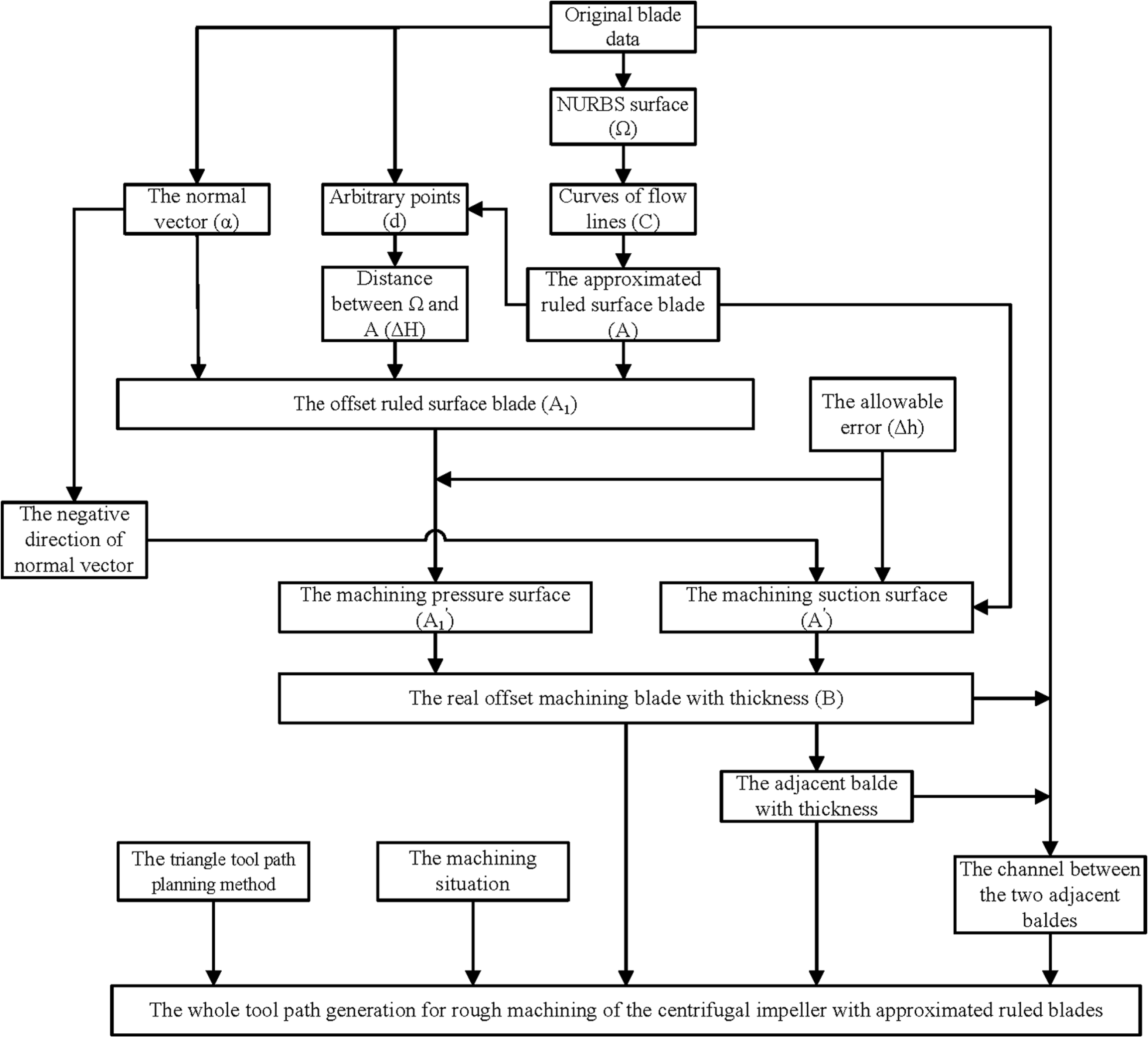
Flowchart of new tool path generation method.
The current CAM software SDRC.CAMAND V14.0 is chosen to do the same process of the same impeller; the difference is that the target channel is restricted by two original arbitrary blade surfaces. Comparing with the channel which generated by using the SDRC.CAMAND V14.0, the simpler channel which restricted by the ruled blade surfaces and the easier algorithm are two unique features of the tool path using the generation method above. Furthermore, with the same allowable error, 2465 mm (using CAM software) and 1698 mm (using the triangle tool path planning method) are two different tool path lengths. The result shows that about 30% path-line length, machining time, and machining costs, such as cutter, lubricant, water, and electricity, and staff costs are saved as a result of using the triangle tool path planning which is targeted to focus on the impeller channel; this is the other difference from using the traditional isoparametric tool path planning which is the universal module of the current CAM software.
Tool path generation of semi-finish machining
After rough machining, most of the metal material has been removed and the approximated ruled blades already appear. Compared with the original solid block, a bathtub construction with the approximated ruled blades is obtained. However, the blade surfaces remain too crude for the finish machining. Therefore, the main target of semi-finish machining is distinct from that of rough machining. The precision of the blade surfaces, rather than the high efficiency of material removal, is the main purpose in semi-finish machining. Obviously, the approximated ruled surface blades formed by the suction surface
Generation of the sub-ruled surface blades
The same NURBS blade surface
From shroud edge to hub edge,
Get an initializing ruled surface blade
A parameter
For the whole points in
Compare
If
The algorithm to calculate the first sub-ruled surface is also shown in Figure 9.
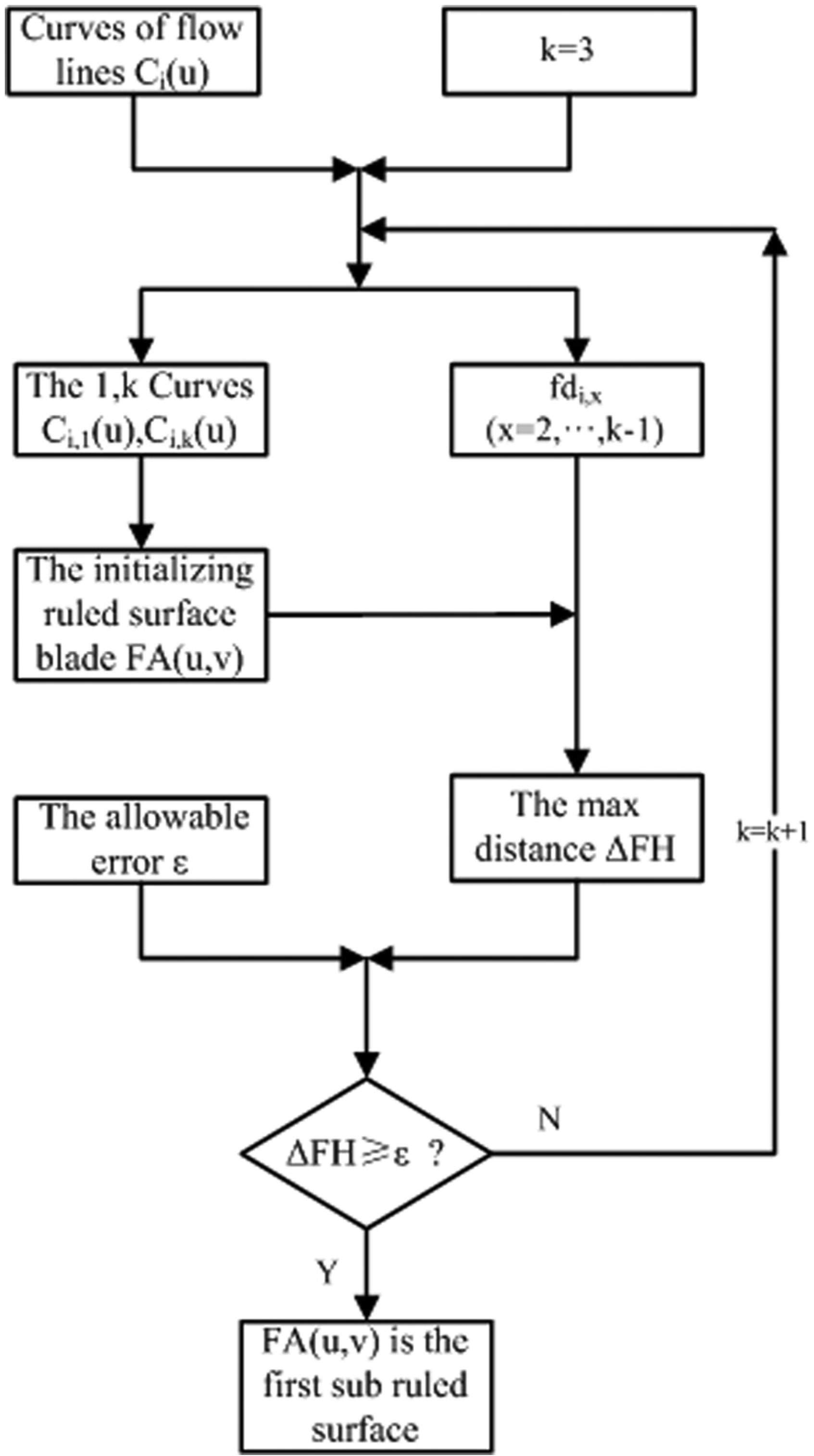
Flowchart of the algorithm to calculate the first sub-ruled surface.
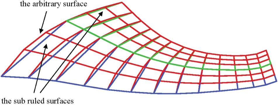
The sub-ruled blade surfaces.
The tool interference of semi-finish machining
An approximate impeller with sub-ruled surface blades can be obtained through the similar processes mentioned in section “The ruled blade with suction surface and pressure surface.” In rough machining above, the channel is the target of the removal of the metal material; the blades are only the interference surfaces. But in semi-finish machining, the blades are both the added targets of machining and the interference surfaces. Specifically, more difficulties appear as the addition of the machining and interference surfaces. A new method for the tool interference checking is necessary.
For semi-finish machining of the blades, the flank milling method of non-developable ruled surface is the best choice. Chu and Chen 1 proposed an approximate developable surface to get the tool path planning for five-axis flank milling of non-developable ruled surface; the method successfully transformed avoidance of tool interference into a geometric modeling problem and provided a simple solution. In this research, the added interference surfaces are the focuses of semi-finish machining of the impeller.
Figure 11 shows a cross section of a channel,
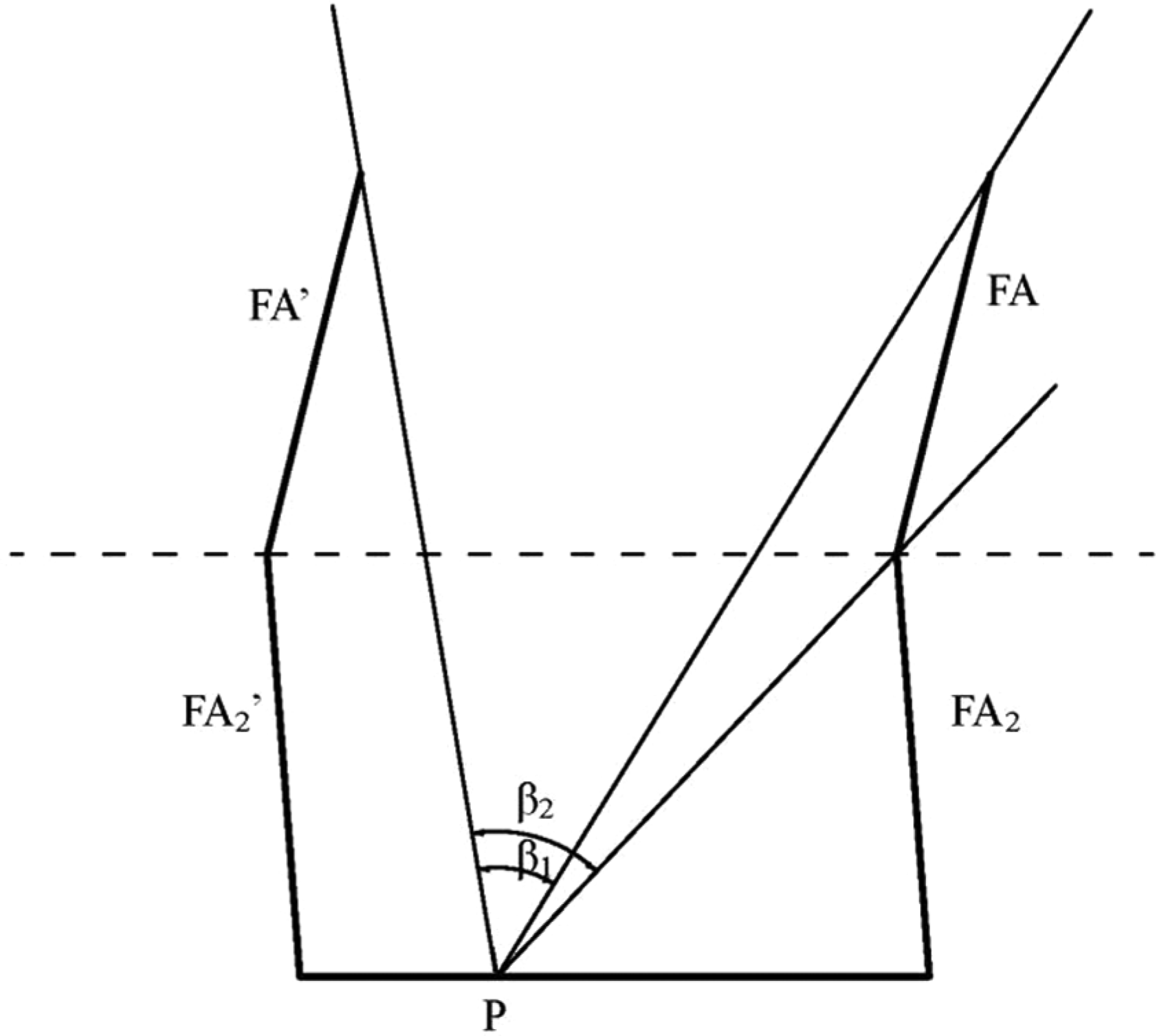
A cross section of a channel.
But for the semi-finish machining of the second sub-ruled surface and the channel bottom, the situation is more complex.
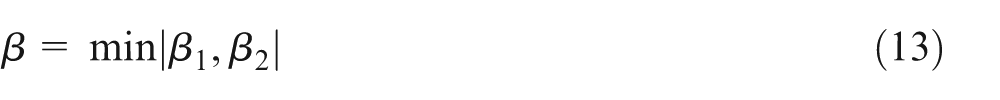
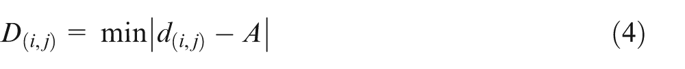
Ignoring the complex geometric modeling problem, for every point on the channel bottom, in the channel or on
The comparison is made between the current machining method using the CAM software SDRC.CAMAND V14.0 and the new method above. With the same allowable error and the machining condition, two different tool path lengths of the same blade are obtained using two different methods. The tool path length is 1277 mm using the current machining method of the CAM software SDRC.CAMAND V14.0, and the tool path length is 344 mm using the new method used in this article above. The result shows that about 70% path-line length, machining time, and machining costs are saved in semi-finish machining.
Machining experiments
The new tool path generation methods of rough machining and semi-finish machining are proposed above. For finish machining, the tool path generation method is very close to the tool path generation method of semi-finish machining, and the differences are accuracy and machining time. That is to say, in finish machining, for the similar maximum distance
For the calculation of the machining experiments,
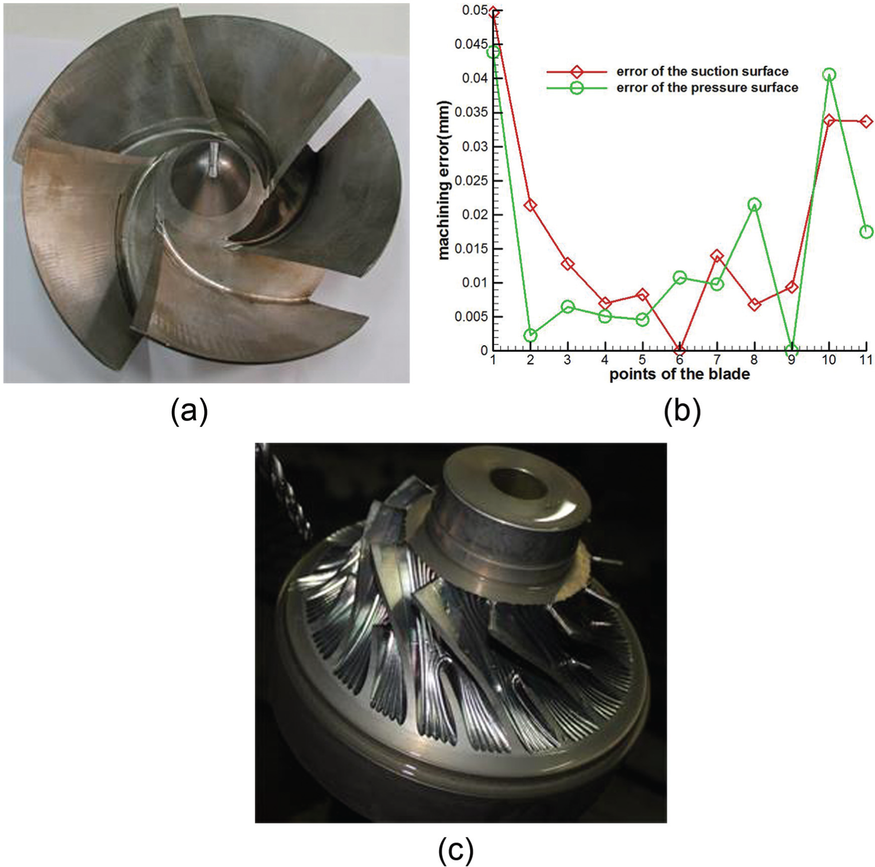
The machining experiment: (a) a finished test impeller, (b) the machining error of the blade, and (c) a test impeller of semi-finish machining.
Figure 12(a) shows a finished impeller. There are five blades for the impeller, and each geometric modeling of the arbitrary blade surface is relatively simple. Therefore, the impeller is finished through rough machining and finish machining. In other words, through rough machining, there is just very small metal residue for the next processor. When two approximate sub-ruled blade surfaces are obtained, the Boolean expression
The extreme difference appears in Figure 12(c), in which the impeller consists of 22 blades (11 blades and 11 splitters), and each geometric modeling of the arbitrary blade surface is very complex. After the rough machining and semi-finish machining, the metal residue is still not enough to finish the impeller blades just through three or four approximate sub-ruled blade surfaces. The research about this is being studied, and the new method and special tools are being researched upon.
Conclusion
In this article, a novel tool-path generation method for five-axis flank milling of centrifugal impeller with arbitrary surface blades is proposed, and it is summarized as follows:
In light of specific characters of different centrifugal impeller blade surfaces, the analyses of two different impeller blades which are named ruled blade surface and arbitrary blade surface are proposed first; compared with the ruled blade, the more characteristic and complex geometrical structures of the arbitrary blade are achieved;
The approximate ruled blade surfaces are calculated in rough machining; the point milling of the centrifugal impeller with arbitrary surface blades becomes the flank milling of the centrifugal impeller with ruled surface blades. The algorithm is easier, and much more machining time is saved. A triangle tool path planning method is proposed in this process. Compared to using the conventional isoparametric tool path planning, with the same path-line number, most lengths of the path-lines are shorter when using the triangle tool path planning method. The results show that about 30% of path-line length is saved; furthermore, a lot of machining costs are saved.
The approximate sub-ruled blade surfaces are calculated to replace the arbitrary blade surface in semi-finish machining; a new flank milling method of the sub-ruled blade surfaces is achieved relative to the traditional semi-finish machining method. For the first sub-ruled surface, the conventional five-axis flank milling of non-developable ruled surface is the simple choice; for the second sub-ruled surface and the channel bottom, a new solution method of tool interference is obtained and a simpler algorithm is obtained compared to the conventional solution method of tool interference.
As the results show, focusing on the machining efficiency improvement, combining the geometric advantages of ruled surface and arbitrary surface, and utilizing the efficient and accurate advantages of flank machining and point machining, this novel and target tool-path generation method for five-axis flank milling of centrifugal impeller with arbitrary blades can successfully achieve efficient machining in rough machining and semi-finish machining. In finish machining, gratifying progress is made in a wide range of areas, but the difficulty faced in this research is still being studied in complex impellers. The new method and special tools follow the research considerations in this research.
Footnotes
Declaration of conflicting interests
The author(s) declared no potential conflicts of interest with respect to the research, authorship, and/or publication of this article.
Funding
This work was partially supported by the National Basic Research Program (973 Program) of China [Grant no. 2011CB706505] and the Shaanxi Province Natural Science Foundation of China [Grant no. 2012JM7004].