
Abstract
A theoretical model of annular upward flow in vertical narrow channel heated from one side has been developed based on the fundamental conservation equations of the vapor core and liquid film. The experimental verification is performed to research on the flow boiling and heat transfer characteristics by setting up visualization platform with the channel that heated from one side. Through solving the closed equations of proposed model by numerical method, the film heat transfer coefficient for vertical two-phase flow is obtained. The results show a good agreement for the local heat transfer coefficient between theoretically calculated results and experimental data. Its mean absolute percentage error is 13.8%. With the applications of the proposed model, further study on the effects of several parameters (such as the cross-sectional width, mass velocity, and effective heat flux) on the liquid film thickness along the channel and radial velocity distributions in the liquid film are conducted.
Introduction
Over the last decade, the study on narrow channel heat sinks have become one of the hot topics and have attracted the attention of a large number of researchers due to its high heat transfer efficiency and compact structure. The possibility of bringing huge advantages by mastering this technology has highlighted this subject in the field of thermal science. Additionally, prediction of the local heat transfer coefficient is one of the important steps for the design of high-efficiency heat exchangers. Many experimental studies on two-phase flow and boiling heat transfer characteristics in channel have been carried out recently by researchers from various countries, such as those presented by Basu et al., 1 Gasche, 2 Diani et al., 3 Kouidri et al., 4 Anwar et al., 5 Huang et al., 6 Chen et al., 7 Shen et al., 8 and Harirchian and Garimella 9 The visualization experimental results had indicated that the annular flow is one of the primary flow patterns in narrow channel. 10
Annular flow is a particularly important flow pattern. A continuous and unstable liquid film covers the inner surface of the channel in the annular region, while vapor and entrained droplets flow into the central vapor core. At the vapor–liquid interface, mass transfer process of liquid film evaporation, droplets entrainment, and droplets deposition occurred simultaneously. Through theoretical analysis of liquid droplets deposition and entrainment process based on reasonable assumptions, the empirical correlations of liquid droplets entrainment rate and deposition rate for different channels and different conditions are obtained, which have great significance for developing a theoretical model of two-phase annular flow. Holowach et al. 11 developed an upward co-current annular flow model based on a force balance and stability analysis and predicted the liquid droplet entrainment rate of annular flow region. Okawa et al. 12 measured deposition rate of droplets in vapor–water annular two-phase flow in a 5-mm-diameter vertical circular tube and presented the correlations for liquid droplet deposition rate. The mechanism of entrainment and deposition of annular flow is analyzed based on different assumptions and research methods, and the correlations for droplet entrainment rate and droplet deposition rate under different conditions are given by Ueda et al., 13 Okawa and Kataoka, 14 Schubring and Shedd, 15 Paleev and Filippovich, 16 Kataoka et al., 17 and Hewitt and Govan. 18 On the basis of the above literatures, many researchers such as Du et al., 19 Sudo, 20 Kim and Mudawar, 21 Fu and Klausner, 22 and Su et al. 23 have proposed the theoretical model for annular flow in narrow channel, round tube, and annular gap tube, but the literature about the annular flow model in the one-side heated vertical narrow channel is relatively scarce. Thus, it is necessary to further study the annular two-phase flow in vertical narrow channel heated from one side.
Theoretical model of annular upward flow
Figure 1 schematically illustrates the annular flow model in vertical narrow channel heated from one side. As can be seen, liquid phase flows partly in liquid film adjacent to the inner wall of channel and partly as droplets in vapor core;

Schematic diagram of annular flow model in narrow channel heated from one side.
Assumptions for annular flow
Annular upward flow for saturated flow boiling is considered as a typical process of heat and mass transfer. For model simplification, several basic assumptions have been made as follows:
The flow is considered as a one-dimensional steady-state and incompressible flow.
The influence of narrow side on liquid film formed on wide side is assumed to be neglected.
The pressure across the narrow channel cross-sectional area is uniform.
The liquid–vapor interface is smooth enough.
There is no slip between the droplets and the vapor, and entrained liquid droplets are uniformly distributed.
The conduction heat transfer along the axial direction is neglected.
Equations of annular flow model
The fluid with a certain sub-cooling degree flows into the narrow channel. Large numbers of bubbles are generated as the liquid is heated along the channel. With the growth of bubbles, they are prone to deformation due to the limitation of the channel size. The bubbles are restricted in the radial direction, which enables bubble extension quickly along the flow direction. Under the action of vapor–liquid interfacial shear stress, the vapor with entrained droplets converges to the center of the narrow channel while the liquid phase is squeezed to the edge of channel finally. When the annular flow in the one-side heated narrow channel reaches a steady state, the heated liquid film covers the heated surface of the channel, and the adiabatic liquid film covers the adiabatic surface of the channel, as depicted in Figure 1. The mass conservation equations of liquid films formed on the heated and adiabatic surface are as follows, respectively. For the heated liquid film

For the adiabatic liquid film

where
In the annular region, the vapor core and the liquid films can be analyzed separately.
24
A microunit is considered. Its height is


where
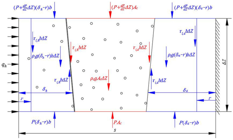
Momentum analysis schematic diagram of annular upward flow model.
The shear stress in the heated and adiabatic liquid film can be obtained from equations (3) and (4), respectively. They are


The shear stress in the liquid film can be used to estimate the velocity in liquid film based on the Newton viscosity law

The boundary conditions of equation (7) are as follows
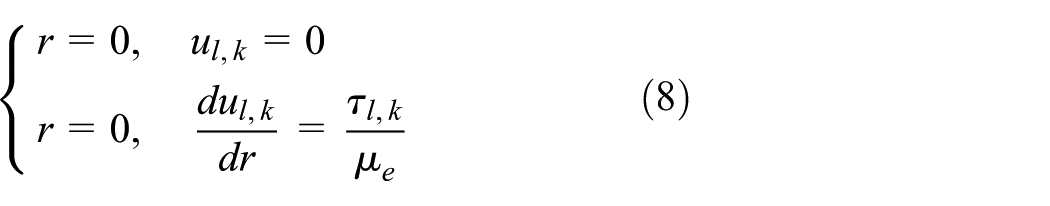
where
The mass flow rate of the heated and adiabatic liquid film can be determined by integrating the velocity, respectively


With the analysis of forces as shown in Figure 2, the momentum conservation equation of vapor core can be expressed as follows

The axial pressure gradient can be calculated by simplifying equation (11). That is

where
The density and mean velocity of the vapor core are very important to the annular flow model and can be expressed by equations (13) and (14)

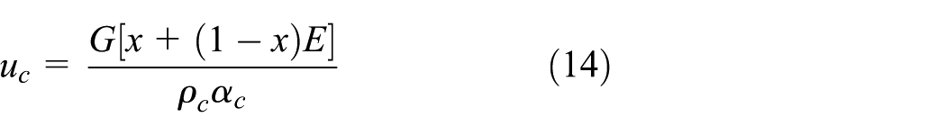
where
The convection can be ignored if the liquid film is assumed to be thin enough. The axial conduction is also neglected according to the assumptions of the annular flow model. Thus, the energy equation of the heated liquid film is as follows

The boundary conditions of equation (15) are as follows

Then, the temperature in the liquid film can be calculated by the energy equation

where
The inner wall temperature is considered to be equal to the temperature in the liquid film at r = 0. Thus, the local heat transfer coefficient can be defined by

where
Solution of annular flow model
Based on separated flow, a mathematical model has been established that is applicable to the annular upward flow in vertical narrow channel heated from one side.
Closed equations of annular flow model
The location of the onset of annular flow can be determined through visual observation. In order to solve the equations of annular flow model proposed above with numerical solution, the variables
The onset of annular flow
The test section of visualization experiment platform is connected by two pieces of A3 steel plates and various components through bolts. It consists of a 4-mm-thick copper plate (material: H69), two steel plates, a 5-mm-thick transparent toughened glass, an electric heater, silicone rectangular sealing rings, and fixing device. The onset of annular flow can be observed through the toughened glass. A scale is installed on the steel plate at the visual side in order to facilitate recording the location of the onset of annular flow. The test section is wrapped with insulation material except the visual window. Thus, the effective heat flux is introduced in equation (1) for avoiding large data processing error caused by heat leakage. That is

where
In the annular flow region, the vapor quality along the flow direction can be calculated by heat balance equation

where
The calculation of interfacial shear stress
The interfacial shear stress is very important to the solutions of the annular flow model. Wallis 25 proposed the correlation of the interfacial shear stress considering the influence of the liquid velocity and droplet entrainment at liquid–vapor interface
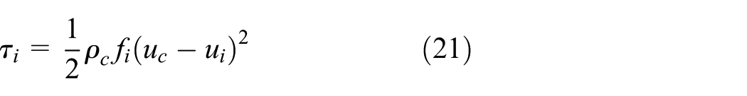
where
Entrained liquid mass fraction
The correlation of the entrained liquid mass fraction is accepted that considering 2460 data points collected from 38 different literature studies of annular flow given by Cioncolini and Thome 27


where
The void fraction
The accurate prediction of the void fraction is crucial in developing the annular flow model. The void fraction can be calculated by the correlation proposed by Cioncolini and Thome 28

The eddy viscosity of the liquid
At present, there is still no effective method to measure the detailed turbulence for the liquid films of annular flow in vertical narrow channel heated from one side. The liquid eddy viscosity is introduced to describe the extent of turbulence in the liquid film by Kays 29

where
The eddy thermal diffusivity of the liquid
The relationship between the liquid eddy viscosity and eddy thermal diffusivity can be given by Celata et al. 31

where
Entrainment rate of liquid droplets
It is considered that the droplets entrainment is composed of two different mechanisms of droplets formation: the wave entrainment

where the recommended values for


where
The boiling entrainment rate due to burst of boiling bubbles can be calculated by the correlation proposed by Ueda et al. 32
Thus, the entrainment rate at the liquid–vapor interface can be obtained by

Deposition rate of liquid droplets
Most of theoretical correlations for calculating the droplets deposition rate are based on a linearity hypothesis that the deposition rate is directly proportional to the concentration of liquid droplets in the vapor core. The deposition rate can be calculated by the equation deduced by Kataoka et al. 17
Calculation procedure of annular flow model
The above equations of annular flow model are closed now. The physical properties of fluid can be queried according to the given test parameters. With the numerical solution to the closed equations, the local heat transfer coefficient, the liquid film thickness, and radial velocity distributions are obtained. Figure 3 is a flowchart illustrating the solving procedure, which also can be summarized as:
The location of the onset of annular flow is determined by experimental observation. Equation (20) is used to compute the initial vapor quality of annular flow
The region where the value of the vapor quality is greater than
An initial value is assumed for the interfacial velocity
Equations (5)–(8) are used in conjunction with equation (25) to calculate the heated and adiabatic liquid film velocity distributions:
Check if the initial interfacial velocity assumed in step (3) equals to the calculated interfacial velocity in step (4). If not, adjust the initial value of the interfacial velocity, and repeat steps (3)–(5).
Equation (9) is employed to calculate the heated liquid film mass flow rate
The heated and adiabatic liquid film mass flow rate also can be calculated by equations (1) and (2), which can be represented by
Check if

Flowchart of calculation procedure.
Experimental equipment and verification
A visualization experimental platform for flow boiling in the one-side heated vertical narrow channel is designed and built for verification of the proposed annular flow model.
Experimental facility
The experimental apparatus system is shown in Figure 4. The experimental apparatus mainly contains the test section, a DC power supply, a condenser, a pump, an electromagnetic flow meter, a pressurizer, and an electrical pre-heater. Deionized water is used to investigate the flow boiling characteristics in vertical narrow channel heated from one side. The fluid flows through the electromagnetic flow meter, the pre-heater, the test section, and the condenser, then returns to the pump which is used for fluid circulation. The electromagnetic flow meter with the accuracy of ±0.3% of the test span is used to measure the inlet mass flow rate of the test section, and the maximum flow rate is 1.8 m 3 /h. The pre-heater is mainly used to control the inlet temperature of the test section, and its maximum electric power is 60 kW. The test section is heated by a DC power supplied with a 120 kW maximum electric power. The pressurizer is connected with high-pressure nitrogen (N2) cylinder, and the system pressure is regulated by adjusting the charge of N2 through the nitrogen charging line. The maximum system pressure is 0.5 MPa due to the limitation of the structure design of the test section.

Schematic diagram of the experimental apparatus system.
Figure 5 schematically illustrates the structure of the test section. The cross-sectional size of the test section is 2 mm × 260 mm. The heated wall temperature is measured from 10 type-T thermocouples evenly along the test copper plate section. The location of 10 thermocouples which are placed into the 2-mm small holes opened in the side of the copper plate to measure the wall temperature are as follows: z = 0.11, 0.24, 0.37, 0.50, 0.63, 0.76, 0.89, 1.02, 1.15, and 1.28 m. The measurement error of thermocouples is less than 0.5°C. The uncertainty of direct measurement parameters is shown in Table 1.

Structure of the test section.
The uncertainty of experimental parameters.

Model verification
A total of 319 experiment data points are used to verify local heat transfer coefficient obtained by proposed annular flow model, as shown in Figure 6. The theoretically calculated results have a good agreement with the experimental local heat transfer coefficient with a deviation of ±20% and a mean absolute percentage error (MAPE) of 13.8%. A further analysis shows that about 73.4% local heat transfer coefficients of the calculation are larger than those of experimental data. There are two explanations for this phenomenon. The first reason is that the wall temperature measured by experiment is actually the internal temperature of copper plate and is theoretically slightly larger than the surface temperature of copper plate theoretically. In other words, the wall temperature obtained by experiment is larger than that of the proposed model. The second reason is that the thermocouples have a calibration accuracy of ±0.5°C. The first one is the primary cause.
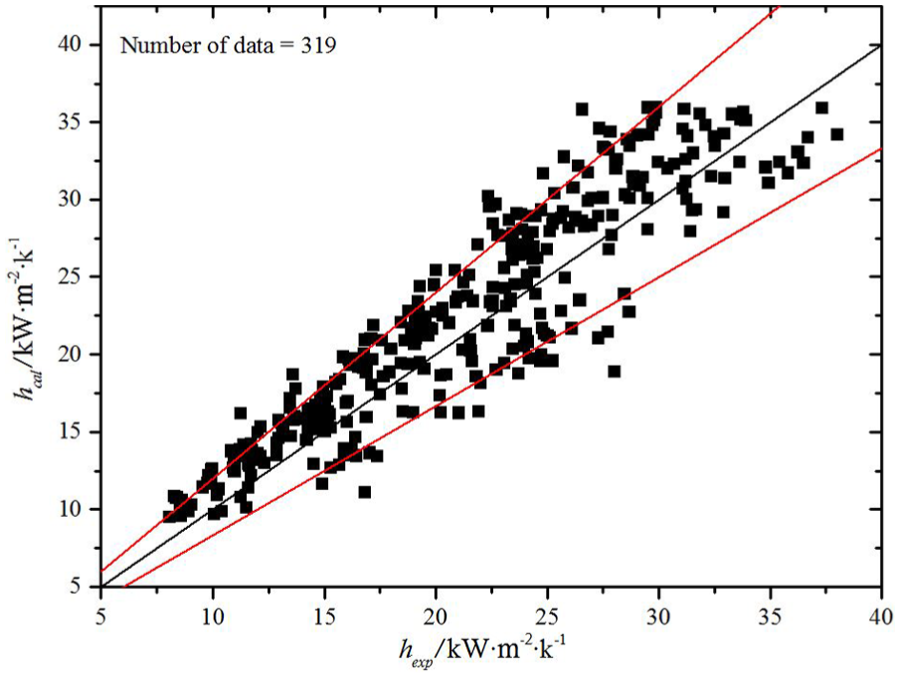
Comparison of the local heat transfer coefficient between the present model and experiment.
Figure 7 shows the local heat transfer coefficient of annular flow changes with the axial distance. The heat transfer coefficient increases with the increment of axial distance, and the change trend of heat transfer coefficient of proposed model is similar to that of experiment.
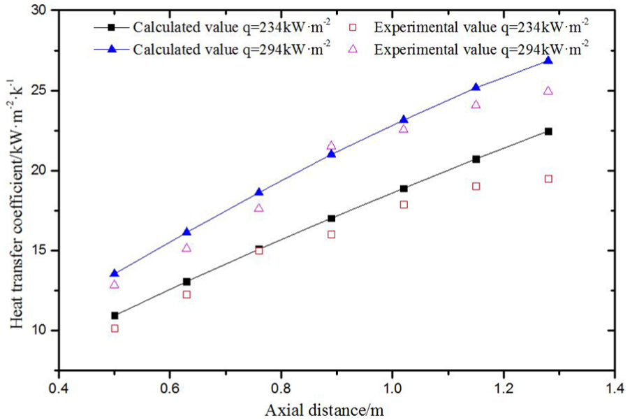
Local heat transfer coefficient between the present model and experiment in the axial direction.
It is proved that the proposed annular flow model is reliable to predict two-phase local heat transfer coefficient. Therefore, further theoretical researches on the characteristics of annular flow can be done, which has a great significance for a deeper understanding of the heat transfer mechanism of annular flow in vertical narrow channel heated from one side.
Results and discussion
In order to further study the characteristics of annular flow in one-side heated narrow channel, the heated and adiabatic liquid film thickness, the velocity distributions in the liquid films are obtained by solving proposed annular flow model.
The liquid film thickness distributions
The liquid film thickness to axial distance with different cross-sectional width, mass velocity, and effective heat flux are shown in Figure 8. Owing to the combined influences of liquid film evaporation, droplets deposition and entrainment, both of the heated and adiabatic film thickness will decrease with the increment of axial distance. Under the same conditions, the heated film is thicker than the adiabatic film. The reason for this result may be that the one-side heated surface needs a large wall superheat to maintain a steady flow state of annular flow comparing with that in the peripherally heated channel. Therefore, according to Fourier’s law of heat conduction, the heated film in one-side heated narrow channel will become thicker with increase in the wall superheat under a certain heat flux condition.

The heated and adiabatic film thickness in the axial direction: (a) effects of cross-sectional width on the heated film thickness, (b) effects of cross-sectional width on the adiabatic film thickness, (c) effects of mass velocity on the heated film thickness, (d) effects of mass velocity on the adiabatic film thickness, (e) effects of effective heat flux on the heated film thickness, and (f) effects of effective heat flux on the adiabatic film thickness.
As shown in Figure 8(a) and (b), the heated and adiabatic film thickness will increase with the increment of cross-sectional width. The narrowing of the channel will result in the increasing of suppression effect to the film thickness. That is to say, the suppression effect will decrease with increasing cross-sectional width, and it is conducive to fully develop the liquid film thickness of annular flow. Moreover, the transported liquid will obviously increase as the cross-sectional width increase at a constant mass velocity. Therefore, both the heated and adiabatic film thickness will increase. Figure 8(c) and (d) shows that the heated and adiabatic film thickness will increase with the increasing of mass velocity. The main reason for the increase in film thickness is that the transported liquid obviously increases with the increment of mass velocity. The changing curves of the heated and adiabatic film thickness corresponding to axial distance with different effective heat flux are shown in Figure 8(e) and (f), respectively. With increasing effective heat flux, the heated and adiabatic film thickness will decrease due to increasing evaporation rate of liquid film. In the meantime, the increase in the evaporation rate will bring an increase to the velocity of vapor core; the interfacial shear stress will become bigger; the drag effect on the liquid film caused by interfacial shear stress will increase, which makes the heated and adiabatic film become thinner.
The velocity distribution in the liquid film
Figure 9 presents the velocity distributions in the heated and adiabatic liquid film.

The velocity distributions in the heated and adiabatic liquid film: (a) velocity distribution in the heated liquid film with different cross-sectional width, (b) velocity distributions in the adiabatic liquid film with different cross-sectional width, (c) velocity distributions in the heated liquid film with different effective heat flux, (d) velocity distributions in the adiabatic liquid film with different effective heat flux, (e) velocity distributions in the heated liquid film with different mass velocity, (f) velocity distributions in the adiabatic liquid film with different mass velocity, (g) velocity distributions in the heated liquid film at different locations along axial direction, and (h) velocity distributions in the adiabatic liquid film at different locations along axial direction.
It can be found from Figure 9 that the velocities of heated liquid film are obviously faster than that of adiabatic liquid film under the same condition. The reasons for this phenomenon may be that the fluid in the heated side is evaporated when heated, the volume increases rapidly and the bubbles also have a certain driving effect on the heated liquid film in the early stage of the bubble departure, which finally lead to the heated liquid film flowing faster. Figure 9 also indicates that the velocities of heated and adiabatic film have different change trends under the same conditions. When the non-dimensional distance from the wall increases from 0 to 1, the velocity gradient of heated liquid film remains almost unchanged first, then decreases and finally increases rapidly. That is because the flow is in laminar flow region near the heating wall, the radial velocity distribution in the heated liquid film is nearly linear within laminar flow region, and the velocity gradient of liquid film is big since the thickness of laminar flow region is small enough. With the increment of the non-dimensional distance, the flow becomes turbulent. As a result of irregular motion of fluid particles in turbulent flow, the fluid velocity trends to be homogeneous, which make the gradient of film velocity decrease finally. Owing to the drag force of vapor to fluid, the velocity gradient increases markedly near the vapor–liquid interface. But the irregular motion of fluid particles makes that the drag effect on fluid only can maintain a very short distance from the vapor–liquid interface. The velocity distribution in adiabatic film is nearly linear when the liquid velocity at vapor–liquid interface is lower than 2.5 m/s that is because the drag force of vapor to liquid film is relatively small and the adiabatic film is almost in laminar flow region. But when the liquid velocity at vapor–liquid interface becomes faster than 2.5 m/s, the velocity distribution in the adiabatic film tends to be similar to that in the heated film due to the enhancing of drag effect of vapor on liquid film.
Conclusion
The fundamental conservation equations of the vapor core and liquid film have been used to build a theoretical model of annular upward flow in vertical narrow channel heated from one side. The numerical method has been applied to solve the closed equations of the proposed model. The local heat transfer coefficient, liquid film thickness, and velocity distributions in the liquid films have also been obtained. A further study on the characteristics of annular flow has been conducted with the applications of present model. Through analyzing the results, several conclusions from the study are as follows:
The local heat transfer coefficient of vertical narrow channel with one-side heating can be predicted well by annular flow model. The comparison of local heat transfer coefficient between experiment and calculated results shows that the deviation is ±20%, and the mean absolute error is 13.8%.
Under same conditions, the heated film is thicker than the adiabatic film, and the velocity of heated liquid film is larger than that of adiabatic liquid film.
Under same conditions, the thickness of heated film has the same changing tendency with that of adiabatic film. The film thickness increases with the increment of cross-sectional width and mass velocity but decreases with increasing effective heat flux.
In the annular flow region, the velocities of heated and adiabatic film increase with the increase of mass velocity and effective heat flux, while decrease with an increased cross-sectional width. With the increment of non-dimensional distance from the wall, the velocity gradient of heated film remains uncharged first, then decreases, and finally increases rapidly. But the velocity distribution in the adiabatic film seems to be related to the liquid velocity at vapor–liquid interface. When the liquid velocity is lower than 2.5 m/s, the velocity distribution in adiabatic film is nearly linear, and when the liquid velocity is faster than 2.5 m/s, the velocity distribution in adiabatic film is similar to that in heated film.
Footnotes
Appendix 1
Academic Editor: Hyung Hee Cho
Declaration of conflicting interests
The author(s) declared no potential conflicts of interest with respect to the research, authorship, and/or publication of this article.
Funding
The author(s) disclosed receipt of the following financial support for the research, authorship, and/or publication of this article: This work was funded by opening project of Shanghai Key Laboratory of Multiphase Flow and Heat Transfer in Power Engineering (No. 13DZ2260900), to which the deepest gratitude should be paid.