
Abstract
This study is on the dynamic analysis of long heavy-duty roller chain drive systems, which is used in a bucket elevator of continuous ship unloader. Currently, most dynamic analysis is focused on part of the driving system, such as a chain tight span. However, it is not enough for the practical application. To simulate the unloading process more precisely, the dynamic response of the roller chain during working was simulated used a geometric modeling with Automatic Dynamic Analysis of Mechanical System. The major objective of this work is to study the factor analysis of long heavy-duty roller chain system for bucket elevator of continuous ship unloader. The aim of this article is to analyze the dynamic behavior of the complex chain system. The results are expressed in terms of parameters such as angular velocity, angular acceleration, contact force, driving sprocket torque, roller chain tension, and displacement. It shows that as a multi-body model, the roller chain system has a complicated dynamic characteristic. The results from the dynamic simulation can help to better the choice of parameters. Maximum contact force and chain tension positions of the chain system model are determined and can be used in the following finite element method analysis. In addition, influence of the speeds on the kinetic parameters is also simulated and critical speed is deducted through the lateral displacement analysis.
Keywords
Introduction
To deliver products in an efficient and fast way is necessary in modern society. The continuous ship unloader (CSU) is widely used to meet the above requirement. Chain drives are easy to assemble and adjust, highly efficient, durable, reliable, compact, and capable of attaining a wide range of power and speed capacities. Chain drive system can be widely found in conveying applications as an effective way of transmitting power. 1 Therefore, it is utilized in the CSU in this research. The CSUs are constituted by large-size components and having complex structures. The size of the chain makes the system stiffer than the smaller chain drive systems and the computation has to be made with a focus on minimizing the simulation time. 2 In practice, the vibration and noise often affect the working parameters of the roller chain, such as the frequency and amplitude of the chain. 3 So, the related study is carried out and becomes a popular topic. In the past 20 years, many research concerned on the theoretical analysis. But the whole process is a complex one and it is difficult to get the precise result. Therefore, the simulation technology was applied widely. For example, recently, researchers have turned to kinetic analytical methods as a means for chain–sprocket interaction and chain drive. 4
Theoretical analysis, experimental research, and numerical simulation are the main approaches for the chain drive system. For example, in some studies,5–7 mechanical models of a chain drive system are proposed and applied to the theoretical analysis of chain drive system of a certain type of heavy-duty apron feeder. Then, multi-body dynamics models are established for the verification of theoretical results and dynamic simulation. Currently, development of computers has made it easy to numerically solve some of the equations given in complicated mechanisms of the chain drives. As the world’s most famous and widely used Multibody Dynamics (MBD) software, Automatic Dynamic Analysis of Mechanical System (ADAMS) improves engineering efficiency and reduces product development costs by enabling early system-level design validation and will be utilized in the following research.
The existing references comprehensively involve the influence of some parameters on the driving, such as the load distribution the meshing impact, the polygonal action, and the method of reducing the vibration, and most of these analyses are based on the simple chain drive.8–10 However, to meet the requirement of the practice complex, chain drive system is needed. It usually has special dynamic behavior for the peculiar structure and service environment. The objective of this article proves to build a model in ADAMS software and using simulation method to analyze the dynamic behavior of the long heavy-duty roller chain drive systems.
Modeling, theoretical analysis, and simulation
Chain system modeling
As shown in Figure 1, heavy-duty roller chain drive systems, which is used in a bucket elevator–type CSU is an important part of the CSU. A bucket elevator–type CSU is used for both a sidewise shoveling operation and a catenary cleaning up operation. 11 The digital picture of bucket elevator CSU unit and the component parameters of roller chain system are shown in Figure 1 and Table 1, respectively. The specifications of the chain are given below:
Chain length: 93.8 m;
Pitch: 350 mm;
Roller diameter: 130 mm;
One link weight: 137 kg/m;
Total number of chain link: 268 EA;
Chain breaking load: 360,000 kgf.

A bucket elevator–type CSU.
Parameters of the components in roller chain system. 12
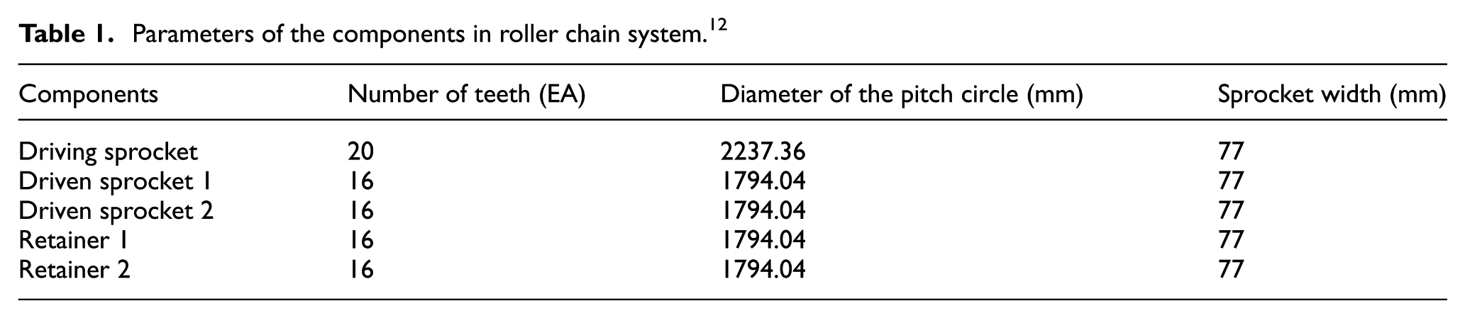
Figure 2 shows the heavy-duty roller chain drive system layout. It indicates that the model consists of one driving sprocket, two driven sprockets, two retainers, and the long roller chain. Driving sprocket supports the force to put the bulk cargo in the bucket. Two retainers are designed to provide sufficient tension to ensure the normal operation of institutions. In this study, counterclockwise direction is set to positive direction. The sprocket rotates counterclockwise and retainer rotates clockwise and has a negative value.

Roller chain system modeling.
Theoretical analysis
It is known that the chain is composed of rigid link through the hinge pin shaft. When the chain is running on the sprocket and meshing with the corresponding chain gear, this chain becomes a part of the regular polygon, as shown in Figure 3 (two different positions). The regular polygon side length is equal to the pitch link and the number of edges is equal to the sprocket teeth.

Polygon effect in chain drive: (a) Tip (crests) diameter position and (b) Root (trough) diameter position.
An alternative angle of present during the chain motion due to sprocket shape as shown in Figure 3. The kinematic characteristic of chain drive is called polygon effect. When the drive sprocket rotates at a constant speed, due to the polygon effect, linear velocity of driving chain and angular velocity of driven wheel change and this kind of change is cyclical. The CSU model consists of a sprocket and a retainer. The system configuration changes according to the polygon effect, the speed relationship of the drive chain, and the drive tension.
When the driving sprocket rolls with a constant angular velocity, the chain linear velocity is constantly changing. Equations (1) and (2) show the speed of the vertical direction and horizontal direction of positions, as shown in Figure 3


where r1 is the radius of sprocket standard pitch circle and
During the chain driving process, impact occurs from the transmission characteristics of itself (as mentioned above). The velocities of colliding bodies change rapidly, and the reactions are impulsive in nature.
Simulation conditions
The large roller chain drive systems are stiff systems for the numerical integration routine to solve, so the simulation time is large. The use of the nonlinear contact force model combined with the overall motion of the roller chain drive system leads to rapid changes in the velocities and accelerations, which explain why the system is stiff. In order to prevent that the numerical errors of the results increases, a small time step must be applied.13,14
A short simulation time is desirable and discontinuities are avoided as far as possible. In order to minimize the simulation time, several approaches are implemented for the upstart of the integration to be smooth. As shown in section “Chain system modeling,” the chain length is 93.8 m, under different speeds (1, 1.5, 2, 2.5 m/s), it takes 93.8, 62.53, 46.9, 37.25 s to drive one cycle. So, in order to simulate the one intact cycle, at least 93.8-s time should be used to analyze. Two types of simulation times are carried out, in order to get the characteristic of the special roller chain system: 5 s is used in the process and 500-s time is used to analyze influence of speed during the simulation. Step size is 0.01 s in all simulations.
Results and discussions
In this research, dynamic response of the system, such as angular velocity and angular acceleration, will be analyzed in detail. Some parameters, which will be useful in the practical application, such as contact force, driving sprocket torque, roller chain tension, and displacement, will be analyzed in different driving speeds.
Angular velocity and angular acceleration
Angular velocity
There are two kinds of angular velocities in the chain system: one is constant angular velocity the other is oscillating angular velocity. It means that in the chain system, the sprocket rotates at a constant speed. For the sprocket wheel polygon effect, the angular velocity in driven sprockets and retainers will not be constant. The angular velocities of each sprocket are shown in Figure 4. Kinematics regularity of the sprockets can be obtained from the results. Driving sprocket angular velocity is a constant value. Angular velocity–driven sprockets do periodic vibration with driving sprocket angular velocity as the center.

Angular velocity of sprockets.
As the driving sprocket rotates, the teeth and the roller come in contact with each other, and then the force is applied to the sprocket. The acceleration peak is shifted in the vertical direction with respect to the traveling direction of the chain, and the peak period is changed. The retainer rotates in the direction opposite to the driving direction and shows a negative value. The retainer has the dynamics of applying a sufficient tensile force to the chain.
Angular acceleration
From Figure 5, it can be seen that there is variation in the angular acceleration, and with obvious impact vibration phenomenon, a series of peak values appear. These phenomena make noise and vibration in the process of chain drive and accelerate the sprocket and chain link between the wear and tear. The larger impact will cause greater damage to the chain system. From the simulation results (Figure 5), it shows that compared to peaks of angular acceleration of the sprockets, the retainers have higher peaks than the driven sprockets at the beginning. But as the drive process continues, all the peaks are controlled in a relatively stable area.

Angular acceleration of sprockets.
Characteristic of driving sprocket torque
For the driving sprocket, a very large inertia moment is considered to ensure its rotation with a constant angular velocity throughout the analyses carried out in this work. The initial torques of different speeds are analyzed and shown in Figure 6. It shows that there is a short transient response when the chain is just starting and finished when the first rollers contacted with the sprockets. Afterward, the chain works in the transversal vibrations, and the polygon effect and the strand length variation become steady. During this process, all the links on the chain have the similar kinematic behavior. It means that the maximum driving sprocket torque usually occurs at the beginning of the driving, and in the following time, it keeps a relatively stable running. So, as mentioned in section “Simulation conditions,” the simulations under different speeds are carried out with a 5-s simulation time. The driving sprocket torque waveform is shown in Figure 6. It shows that the torques distribute according to certain diminishing rules until a stable running is reached.

Driving sprocket torque in different speeds.
The torque that the drive sprocket has while driving is shown. In the beginning, a large force is required, and the torque value stabilizes and becomes smaller after a certain period of time. Figure 7 shows the maximum value of the initial torque of the drive sprocket.

Influence of simulation speed on maximum driving sprocket torque.
It also shows that the higher speed of the roller chain needs higher driving sprocket torque. This means that the initial torque value needed to drive the high speed is greatly needed. Comparing the maximum torque in different speeds (Figure 7), it shows that increase in the same value of the speed in higher speed (1.5–2.5 m/s) can influence the sprocket torque obviously than in lower speed (1–1.5 m/s). At 0.5 s, the time at which the first roller and the sprocket mesh with each other while driving the drive sprocket is equal to the peak occurrence at the beginning. This is because the sprocket and the roller contact each other at the 0.5 s position at the point where the constant velocity is not reached at the initial velocity, and the peak value is obtained. Thereafter, the peak is stabilized while decreasing, and the peak point changes with time depending on the speed.
The sprocket teeth and rollers contact and have a positive torque value. Then, the torque is dropped while rotating. At that time, the value of the torque received at the same position becomes small. This means that when one sprocket tooth is seen, it touches the left side in the beginning, then touches the right side, and then repeats positive and negative while receiving the opposite torque force.
The driving sprocket torque analysis at a speed of 1.5 m/s showed comparatively stable results due to transfer efficiency. Torque results at a speed of 1.5 m/s show a tendency to decrease constantly.
At other speeds, there is no tendency for the torque to decrease steadily. As the roller chain rotated, irregularities occurred in the direction perpendicular to the traveling direction.
Contact force
Maximum contact force determination
The contact force between the chains and sprockets is the major part of investigation. From the dynamic analysis, maximum contact force can be confirmed. As shown in Figure 8, the maximum contact force occurs when the sprocket and the roller chain are in contact. There are variations in different cycles because the contact angle of gears and chains cannot guarantee completely consistent when they contact with each other.

The position of the maximum contact force.
Influence of speed on contact force
The changes of the contact between the chain plates and sprockets under different driving speeds will be discussed in detail. To show the dynamic behavior of this chain driving system, one cycle is simulated for the contact force. As shown in Figure 9, one driving cycle (in 2.5 m/s, one cycle time is 37.25 s) can be divided into four stages. In the first one, there is no contact, so the contact force is zero. The maximum contact force occurs when the link enters the driving sprocket (second stage). Figure 9 shows the contact force of the roller chain 1 link as it moves. During 1 week of rotation, all seven peaks appeared. It appears to be engaged with the sprocket two times in the driving sprocket, one time in the retainer 1, one time in the retainer 2, two times in the driven sprocket 2, and one time in the driven sprocket 1, all having seven peak values. This peak value refers to the force received by the sprocket and the roller in contact with each other and is repeatedly displayed every rotation. The maximum contact force differs per rotation. This is because the chain is driven and the difference is caused by the shaking in the vertical direction. As in the first stage, the value of contact force is 0 and then link 1 gets to driven sprocket area, as shown in Figure 9. In consideration of the distinction in every cycle, to get a more accurate result, a long simulation time is used in this section, and the contact force in different speeds is shown in Figure 10.

Contact force in one cycle.

Contact force in different speeds: (a) 1 m/s, (b) 1.5 m/s, (c) 2 m/s, and (d) 2.5 m/s.
From the above results, the maximum contact forces in different speeds can be obtained and the values are 44761.3, 49598.9, 46925.1, and 45187.2 N, respectively, in 1, 1.5, 2, and 2.5 m/s. Based on the results, the influence of simulation speed on maximum contact force is analyzed in Figure 11. It is clear that there is a peak of maximum contact force in the 1.5 m/s speed.

Influence of simulation speed on maximum contact force.
Roller chain can vibrate noticeably when the frequency of an exciting source is close to one of the natural frequencies of the chain. The major sources of excitement are large cyclic loads, chordal action, and roller-tooth impact. The natural chain frequencies are computed and transformed to the driver sprocket speeds for better understanding. These speeds are named as critical speeds. If the driver sprocket speed is close to one of the critical speeds, the vibrations may occur. In order to verify this critical speed lateral, displacement of the chain will be simulated in the following section.
The contact force fluctuation (the difference between the maximum value and the minimum value) of each speed is calculated and the values are indicated in Figure 12. The tendency chart shows that contact force can fluctuate in the driving process and the fluctuation range increases with the higher speed.

The contact force of each speed.
Lateral displacement
To some extent, the chain of each order natural frequency of transverse vibration has a declining trend with the increase in chain transmission speed. However, other parameters influence on the final results too. In order to find out the resonance velocity, simulations on lateral displacement are carried out. As shown in Figure 13, the lateral displacements of the chain with different speeds are compared to each other. Both the 1 and 2 m/s cases are also high at the beginning, but they can be seen to show stable behavior afterward. In the case of 1.5 m/s, contact force received during initial driving was larger than other speeds. As a result, the vibration in the roller chain was greatly increased, and the displacement in the lateral direction was also large. The results indicate that at the beginning of the driving, maximum displacement occurred for each speed and the displacement in 1.5 m/s is higher than in other speeds obviously. It means that there is a critical speed for the whole roller chain system and it is better to avoid it during the practical applications. It can be used as one of the main reason to explain the results in Figure 13.

Comparison of the lateral displacement in different speeds.
Chain tension
The maximum tension of the chain occurs in the tight side near by the driving sprocket, as shown in Figure 14. Figure 15 shows the chain tension in one cycle and it can be divided into three stages for the whole cycle. In the first stage, the link moves from the driven sprocket 1 to the driving sprocket. During this process, with more links entering this stage, the chain tension becomes larger until meshing with the sprocket and then leaves the sprocket. During this stage (a short stage), the chain tension decreased dramatically near to zero. When the link enters the third stage, from the driving sprocket to the driven sprocket, the chain tension decreases until it reaches to the next cycle.

The position of the maximum tension.

Chain tension in one cycle.
Figure 16 shows the chain tensions in different speeds. The results show that the value of the maximum tension roller chain at all speeds is similar, which is about 100,000 N. Maximum tension is mainly influenced by gravity and speed has no obvious impact on it. However, when the chain system runs under the working status, it will be under variable load with the equipment loading and unloading the cargo. This will be part of the work in the future.

Maximum tension in different speeds: (a) 1 m/s, (b) 1.5 m/s, (c) 2 m/s, and (d) 2.5 m/s.
Conclusion
The dynamic and simulation analyses were carried out to study the long heavy-duty roller chain drive system used in a bucket elevator of CSU. In addition, a designed model was developed based on actual bucket elevator and simulated dynamic responses by ADAMS software. In these analyses, four different speeds were considered, that is, 1, 1.5, 2, and 2.5 m/s. The main conclusions are shown in the following:
The angular acceleration peaks of the sprockets, comparatively the retainers, have higher than the driven sprockets. The components showed more variable load than driving sprocket during the process. The peak of the impact vibration was generated by contacting with the sprocket by rotation force during initial driving. Hence, vibration damping and reduction have to be considered while designing the model for bucket elevator.
The driving sprocket torque analysis, the speed of 1.5 m/s, showed comparatively stable results due to transfer efficiency. At this speed (1.5 m/s), the contact force was maximum and also showed that large displacement of chain refers to critical speed. In addition, the most important point is to avoid the resonance frequency band at this speed while designing the bucket elevator.
The maximum tension of the roller chain fluctuated in initial speed, but no change occurred with higher speed. Hence, the tension of the roller chain totally depends on weight and gravity. Therefore, tension force should be considered while designing the chain. Moreover, impact load is also important due to the maximum weight and fluctuating load.
Using dynamic simulation software, the kinematics and dynamics behavior can be analyzed. The results have important guiding significantly for the design and application of the actual device. Meanwhile, it can provide the initial data for the subsequent finite element simulation.
Footnotes
Academic Editor: Aditya Sharma
Declaration of conflicting interests
The author(s) declared no potential conflicts of interest with respect to the research, authorship, and/or publication of this article.
Funding
The author(s) disclosed receipt of the following financial support for the research, authorship, and/or publication of this article: This work is supported by the National Research Foundation of Korea (NRF) grant funded by the Korea government (MSIP) (nos 2014H1C1A1067175 and 2011-0030058).