
Abstract
The serial cable-driven sheaves, wrapped by cables in a single-sided pattern, inevitably produce synchronous error for their cable deformation influences. The synchronous accuracy is a key technology for two spacecraft successful docking, which is mainly dependent on the adjustment of the preload on cable. This research on single-sided cable-driven sheaves is not well enough because of their complicated cable deformation behaviors under the preload. This makes them a low assembly efficiency and poor assembly quality in guaranteeing their synchronous accuracy. Thus, building a more precise model is essential between the preload and cable deformation in the assembly of the cable-driven sheaves. For this, considering both the way of the cable preload applied and their operating conditions, a predicting cable deformation (angle error) model is first proposed based on the stiffness of cable-driven sheaves. Then, some useful results are obtained through the analysis of the angle error influenced by three dominating parameters (wrap angle, preload, and friction coefficient) and of the parameter sensitivities to angle error. Finally, some experiments verified the model. This article provides a favorable attempt for better controlling the cable deformation and lays a foundation for further investigation on the synchronous accuracy and improving assembly efficiency of the serial cable-driven sheaves.
Introduction
Cable-driven sheaves are being widely used in transmission application (aerospace, ships, wharf, and civil elevator, etc.) for their lightweight, good flexibility, high impact resistance, and intensity, and so on. The cable-driven sheaves in docking mechanisms are serially connected with cables in a single-sided pattern and form a closed-loop transmission, as shown in Figure 1. Relative to ones with cables wrapped in a figure-eight or two-sided parallel pattern,1–3 of which transmission depends on the friction between the cable and sheave, this type of sheaves is mainly driven by the driving sheave pulling the driven one with a cable. Therefore, the transmission failure, caused by cable slippage, cannot occur as a larger torque is loaded for their specially connected way between the cable and sheave.

Structure of docking mechanisms.
However, an angle error is inevitably produced between sheaves for the cable deformation in driving process, which will influence the synchronous accuracy, that is, the difference between the biggest and the smallest wrap angles relative to initial ones in serial cable-driven sheaves, respectively. Actually, to ensure successful docking and sealing requirements of the docking mechanisms, the synchronous accuracy of serial cable-driven sheaves is desired to meet a certain criterion. This mainly depends on their assembly accuracy because of the space environmental limitation. Thus, how to control the cable deformation becomes a crucial issue in the assembly of serial cable-driven sheaves. For this, with respect to synchronous accuracy of the docking mechanisms, many scholars carried out some researches in kinematic aspects. H Zhang et al. 4 pointed out the main factors influencing on synchronous accuracy using ADAMS simulation. T Huang et al. 5 studied motion synchronization. For studying the cable elastic deformation effects on synchronous transmission, Y Zheng et al. 6 built a mechanical model and put forward how to control and reduce the tension and cable deformation. J Li et al. 7 proposed a model for predicting the synchronous accuracy of sheave drives. J Xiao et al. 8 found the main factors affecting motion synchronization and put forward several measures in improving movement synchronization through the orthogonal experiment. However, in view of assembly aspects, the cable deformation effects have not been involved in their studies. Hitherto, due to lack in-depth research in assembly of the serial cable-driven sheaves, their synchronous accuracy is guaranteed mainly by workers’ experience for several assembly cycles. This leads to lower assembly efficiency and higher assembly costs, correspondingly.
Since the synchronous accuracy of the serial sheaves is also affected by such factors as design error, coupling effects between serial cables, cable creep, and friction between transmission parts besides the cable deformation, building a united model is rather difficult to describe it. However, since each of cable-driven sheaves presents similar characteristics under the preload for their serial relationships, this provides us a new method to study them. For this, based on the way of the preload, a prediction model for the cable deformation is proposed in assembly of the cable-driven sheaves. And some useful results are obtained through analysis of the angle error influenced by the dominating parameters and of those parameter sensitivities to angle error. This provides a value reference in controlling the assembly accuracy and improving the assembly efficiency of the docking mechanisms.
Theoretical approach
Force model
Figure 2 shows the way of the preload applied to the cable between two sheaves. The preload F0 used to control the cable deformation is determined by both forces

where θ is the wrap angle, F(θ) represents the cable tension at wrap angle θ, FB1 represents the tension of cable at contact point B1, and μ is the friction coefficient between the cable and sheave.

Way of the preload applied to the cable.
Considering the friction between the cable and sheave, equation (1) is a classic sheave equation, which can be used to establish relations between the cable tension and wrap angle under an exterior force or a load torque.
Then, according to the directions of two forces


where
Cable deformation
Based on Hooke’s law, the strain of the cable on sheave can be expressed as follows

where ε is the cable strain, A is the cable cross-sectional area, and E and G represent elastic and stiffness moduli, respectively.
And the microsegment cable on sheave can also be expressed as follows

where dδ is the differential element of cable deformation, dL represents differential element of cable wound around sheave, R is the radius of two sheaves, and dθ is the differential wrap angle.
Hence

Integrating from 0 to θ, the cable deformation under the tension F(θ) can be written as follows

Equation (7) is used to calculate the cable deformation on wrap angle θ under the tension F(θ). Then, the cable deformation on arc A1B1 or C1D1 can be written as follows

where
And the cable deformation on arc MN or EF can be written as follows

where r is the radius of two deflector sheaves, and
As for three free line segments B1M, NE, and FC1, their deformations can be obtained by Hooke’s Law as follows

where δi represents δ1, δ2, or δ3; Li is L1, L2, or L3; and Fj represents FB1M, FNE, or FFC1, correspondingly.
Stiffness
As shown in Figure 2, the cable of sheaves can be simplified as seven segments according to whether to contact sheaves or not. Each sectional tension is not equal under the preload F0 because of the friction effects between the transmission parts, which makes them produce different deformations, consequently. This indicates that the stiffness of each section is also different under the preload F0. Thus, when the stiffness of the cable-driven sheaves is calculated, it should be analyzed according to the serial relationships among seven sections of cable, as shown in Figure 3.
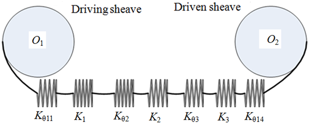
Spring stiffness model of a cable between two sheaves.
Then, the stiffness of cable-driven sheaves can be expressed as follows

where K is the cable stiffness between two sheaves, Ki represents
The stiffness is determined from (1/K) = compliance (dδ/dF). In equations (8)–(10), each cable deformation takes a derivative with respect to their tension and the results are substituted into equation (11), respectively

And the θ14 can be obtained from the geometric relations of cable-driven sheaves as follows

where θ0 = (L − L1 − L2 − L3 − r(θ2 + θ3))/R and θ0 > θ11.
As seen from equations (12) and (13), the stiffness of cable-driven sheaves is mainly influenced by the friction coefficient and wrap angle of the driving sheave.
Deformation model
Under the preload F0, the relations between the cable deformation and stiffness of cable-driven sheaves can be expressed as follows

where δ is the cable deformation under the preload.
The cable deformation is reflected by angle error in the assembly of docking mechanisms. Thus, to facilitate the coming research and coincide with actuality, here the cable deformation is expressed by angle error as well and their relations exist

where the term Δθ angle error is produced by the total cable deformation of the sheaves.
Then, equation (16) can be derived by connecting equations (14) and (15) as follows

where d = R − r.
Equation (16) is a new governing equation that can be used to calculate the cable deformation based on the way of the preload applied to the cable. It can be seen from equation (16) that the angle error is mainly dominated by such three parameters as the preload F0, friction coefficient μ, and the wrap angle θ11. And it is hardly affected by other parameters for the given devices. Moreover, since the cable deformation of cable-driven sheaves is reflected by the angle error, equation (16) can describe the cable deformation through analyzing the effects of above three parameters on the angle error.
Parameter sensitivities
The parameter sensitivities mainly measure its influences on the angle error and reflect how difficult their synchronous accuracy is guaranteed in assembly of the serial cable-driven sheaves. In equation (16), taking derivative of the angle error with respect to the preload, wrap angle and friction coefficient are given, respectively


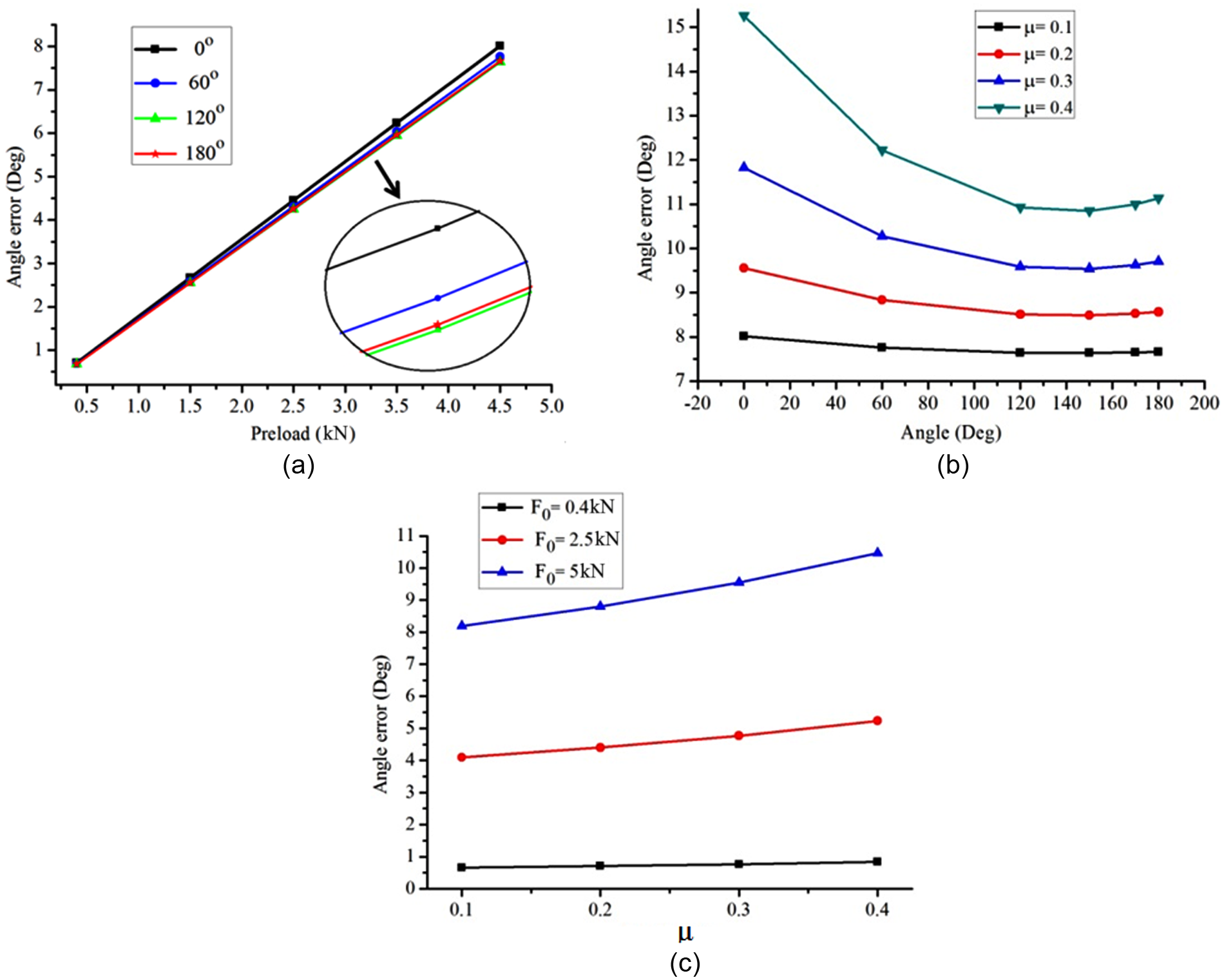
The preload sensitivity to angle error, calculated by equation (17), is shown in Figure 4(a). It is hardly affected by the wrap angle with a friction coefficient smaller than 0.15. However, it becomes larger with the increase in the friction coefficient under the same wrap angle and is more evident especially at a smaller wrap angle. This shows that the angle error is more sensitive to the preload with the increase in friction coefficient at a smaller wrap angle, and thus, the synchronous accuracy of cable-driven sheaves is vulnerable to the preload and is obtained more difficult in assembly, relatively. Moreover, the preload sensitivity decreases with the wrap angle increasing from 0° to 120° at the same friction coefficient. While the wrap angle rises to 180°, it becomes slightly greater, but still far smaller than that at 60°, interestingly. This indicates the assembly accuracy of cable-driven sheaves is easier to obtain with the wrap angle increasing from 0° to 120°. While the wrap angle is at 180°, it becomes difficult slightly relative to 120°. The larger the friction coefficient is, the more evident this trend is.

Parameter sensitivities to angle error: (a) preload, (b) wrap angle, μ = 0.1, and (c) friction coefficient, θ11 = 120°.
Next, for the wrap angle sensitivity of the driving sheave, calculated by equation (18), it is little affected by the wrap angle for a smaller preload 0.4 kN, as shown in Figure 4(b). However, for a preload more than 2.5 kN, it presents from the negative to positive changes with the increase in wrap angle. Correspondingly, obtaining the synchronous accuracy also goes through a process from difficult to easy and again from easy to difficult in assembly of serial cable-driven sheaves. At about 143° (2.5 rad), the wrap angle sensitivity is almost zero, which shows the assembly quality of the cable-driven sheaves is hardly affected by the changes of the preload and their synchronous accuracy is easily guaranteed. But for another wrap angle, its sensitivity becomes larger with the increase in their difference. Correspondingly, obtaining the synchronous accuracy of cable-driven sheaves becomes difficult, relatively. The bigger the preload is, the more significantly this trend presents.
As shown in Figure 4(c), the friction coefficient sensitivity to angle error calculated by equation (19) is very small under a preload smaller than 0.4 kN and is hardly affected by the friction coefficient. However, it becomes larger with the increase in friction coefficient under a preload larger than 2.5 kN. This shows that the angle error is susceptible to a greater friction coefficient, and the synchronous accuracy of the serial cable-driven sheaves is more difficult to obtain under a larger preload. Moreover, the friction coefficient sensitivity also becomes greater with the increase in the preload under the same friction coefficient, which is more distinct for a friction coefficient more than 0.15. This indicates that the angle error is more sensitive to a greater friction coefficient under a larger preload, and the synchronous accuracy of the cable-driven sheaves is acquired much harder, especially for a greater friction coefficient.
By the above analysis, both the sensitivities of the wrap angle and friction coefficient to angle error are reflected mainly by the preload, which both become gradually larger with the increase in preload and also are influenced distinctly by these two factors. From three-parameter sensitivities, the assembly accuracy of serial cable-driven sheaves is terribly influenced by the friction coefficient and then by the wrap angle and the preload. Therefore, to reduce three-parameter sensitivities and improve the assembly efficiency in obtaining the synchronous accuracy of the cable-driven sheaves, the friction coefficient is first controlled smaller than 0.15. Then, if allowed, the wrap angle is desired near 2.5 rad and the preload is applied smaller.
The experimental research
Device
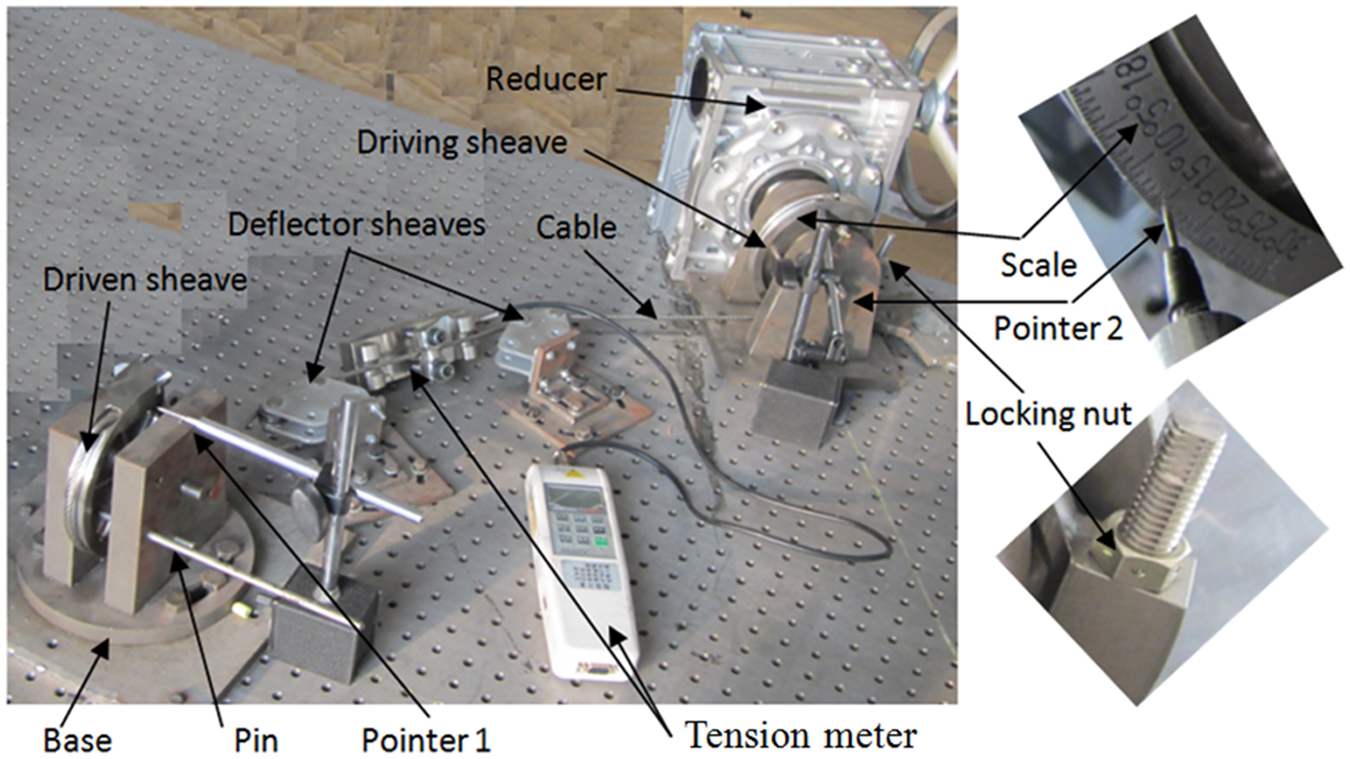
The experimental system for determining the cable deformation of the sheaves mainly consists of a driving sheave, a driven sheave, two deflector sheaves, a tension meter, and a reducer, linked by cable segments, as shown in Figure 5. Here, the preload F0 between two deflector sheaves is exerted by the reducer, a device of self-locking function, and connection with the driving sheave. Its value is read by the tension meter. A scale is on each rim of the sheaves, used to record the wrap angle with a pointer. The wrap angle of the driving sheave becomes larger with the increase in the preload by reducer. Then, the wrap angles of the driving and driven sheaves are collected by specified end angle minus initial one with the pointer, respectively. Correspondingly, the cable deformation is just the difference of above two collected wrap angles. The structural parameters of the whole system are shown in Table 1.
Experimental system.
Device structural parameters.

Experimental scheme
According to the practical assembly requirements, the synchronous accuracy of serial cable-driven sheaves is achieved mainly by controlling the preload in three phases of the docking process (engaging, unlocking, and locking).4–6 For this, to investigate the relationships between the preload and cable deformation, a series of experiments are carried out at wrap angles 0°, 60°, 120°, and 180° of the driving sheave under the working preload smaller than 5 kN, respectively. Here, angle 0° is the starting angle, and others represent the corresponding angles of above three phases, respectively. Meanwhile, in order to decrease the errors produced by the assembly and measurement, the average values of the collecting data are taken as the experimental results. The full procedures are as follows:
Rotate the driving sheave by reducer to locate the cable end A1 at the entrance point B1 and set this point as the starting angle 0° of the driving sheave, as shown in Figure 2. Then, position the driven sheave with pins.
Adjust the cable tension between two deflector sheaves to 0.4 kN as the initial preload with two locking nuts on cable ends.
Calibrate a given angle on each sheave with a pointer, set them as the initial angle, respectively, and regard the angle error of cable-driven sheaves as 0° under this preload.
Rotate the driving sheave clockwise in increment of 1° by reducer until the cable tension rises to its working load 5 kN.
Record the wrap angles of the driving and driven sheaves relative to initial ones and the corresponding preload each time, respectively.
Repeat steps 1 to 5 two more times and complete data collection of three cables at 0°.
Rotate the angle of driving sheave clockwise from 0° to 60°, 120° and 180°, respectively, and complete data collection using above similar approaches at these angles.
In the experiment, it must be noted that a certain error is inevitably produced if three-cable original lengths are different. To reduce it, the wrap angles of two sheaves are first positioned before each test. Then, three-cable original preloads between two deflectors are all ensured 0.4 kN. By this means, the testing lengths of three cables are all equal. Even if they are different from their original lengths, the error caused by those is hardly produced in the test. As for the difference between three original cable lengths, it can be considered in theory calculation.
Experiment results and model validation
The collecting data are wrap angles of two sheaves and their angle error represents the cable deformation under the preload. Figure 6 shows the relations between the angle error and preload at different wrap angles of 0°, 60°, 120°, and 180° under the preload smaller than 5 kN and μ = 0.1. From the graph, each curve of the angle error presents a nonlinear increase with the preload because of the cable viscoelastic and viscoplastic deformation behaviors.10,11 Also, each slope of the curves changes abruptly under a smaller preload due to the cable uneven composition of the steel wires and poor ability to resist deformation. However, the cable performance is improved gradually with the increase in preload. And the slope tends to be constant and the angle error approximately presents a linear increase with the preload. Especially, the effects of wrap angle on the angle error must be noted. Since every cable deformation of four wrap angles is different, the corresponding angle error also changes with preload, inconsistently. The angle error gradually becomes smaller as the wrap angle rises from 0° to 120° under the same preload, while the angle error becomes larger slightly at 180° relative to angle 120°. For better elucidating this, the proposed model is first verified by experiment.

Relations between angle error and preload at different wrap angles.
To illustrate more clearly, the predicted data by model and the experimental results are compared in two groups, respectively, as shown in Figure 7. Since the proposed model is developed on the classic equation without considering the nonlinear performance of the cable, the predicted data present a linear trend with the preload, which leads to an error between them, inevitably. However, their error captures the dominant trends under the given operating conditions and the biggest error is not more than 5% under the preload smaller than 5 kN. This indicates that the elastic deformation dominates in the cable deformation and their error can be accepted relative to the maximum angle error (about 8°). On the other hand, equation (16) can be used to describe the cable deformation by analyzing parameter effects on angle error.

Comparison between experimental results and predicted data under μ = 0.1: (a) 0° and 60° and (b) 120° and 180°.
However, the cable nonlinear deformation, caused by its structure length and physical difference, also influences the experiment results even though the elastic deformation is dormant. Thus, to improve experimental results and reduce the effects of cable nonlinear deformation, pre-tensioning the cable is essential before the test. In this experiment, all the cables were pre-tensioned with weights 5 kN.
Furthermore, by contrast with Figure 7(a) and (b), although the difference of two wrap angles is both 60° in each figure, the fluctuation of angle error in Figure 7(b) is far less than that in Figure 7(a). This is because the wrap angle sensitivity to angle error decreases with the angle increase and it is less affected by the wrap angle. Correspondingly, the experimental data are concentrated relatively and their errors become smaller as well, as shown in Figure 7(b).
Then, the reasons of the angle error caused by the wrap angle in the experiment can well be illustrated by the following two respects. According to equations (1) and (2), the cable tension on the driving sheave becomes larger with the increase in θ11 from its initial angle 0° to the end angle 120° under the same preload. But the one on the driven sheave gets smaller with the decrease in θ14 from its corresponding initial angle 285° to the end 165° (calculated by equation (13)). Since the cable tension is subjected to the exponential function, its changing rate is different even though two angles change equally. This makes the increased tension on the driving sheave smaller than the decreased one on the driven sheave under the equal preload. In this case, the total tension of the cable becomes smaller relatively, which makes the angle error decrease, correspondingly. However, when the angle θ11 is at 180°, the changes of the cable tension on two sheaves are just to the contrary, which leads to the angle error greater slightly.
On the other hand, the whole cable angle on two sheaves can be divided into two parts in driving the process, as stated in the literature.1,2 One is called slip section and the other no-slip section. But for the assembly of cable-driven sheaves, the slip section does not change when the angle of the driving sheave comes into the no-slip one if to exist. Even if it increases, the angle error is still constant for a new cable deformation not being produced in no-slip section. However, it can be seen from Figure 6 that four wrap angle errors are consistently different at the same preload, which shows that the no-slip section cannot exist in the angle θ11 from 0° to 180°. This also elucidates the reason why the wrap angles θ11 and θ14 are not divided into the slip and no-slip sections in building equation (16).
Results and discussion
Factor influences
The study of three-parameter effects on angle error is a base on the analysis and control of the cable deformation in the assembly of cable-driven sheaves. For the term G, it can be obtained by experiment according to the standard 12

In this research, the average value of the tested cables G is about 5.85 × 10⁵ N.
Based on equation (16), the relationships between the preload, wrap angle, and angle error can be found in Figure 8(a) and (b). It is easily observed that the angle error becomes larger with the increase in preload, of which maximum arrives at 8° under the preload 5 kN. For a preload smaller than 1.5 kN, the angle error is little affected by the wrap angle. While the preload exceeds 1.5 kN, the wrap angle influences the angle error distinctly and there is an interesting regularity between them. Specifically, when the angle increases from 0° to 120°, the angle error gradually decreases under the same preload. But after the angle exceeds 120° to 180°, it gets slightly larger relative to that at 120°. However, the angle error presents a linear increase with the preload under the given operating conditions, which is different from the experimental results. This is mainly because the model was developed on the classic equation, which was derived from the cable elastic deformation and did not consider the influence of cable viscoelastic and viscoplastic deformations. Meanwhile, although the proposed model (equation (16)) can be used to predict the angle error and analyze its influencing factors in the assembly of cable-driven sheaves, the model still needs to be further modified.
Relations between three parameters and angle error: (a) preload, μ = 0.1; (b) wrap angle, F0 = 5 kN; and (c) friction coefficient, θ11 = 120°.
By the above analysis, since the angle error is unequal at three phases of engaging (60°), locking (180°), and unlocking (120°) in the assembly of docking mechanisms, their corresponding cable deformation is also different under the preload. It is the largest at engaging, followed by the unlocking and locking. Thus, if the equal angle error is acquired, the preload of three control points should be applied differently. It is the largest at the locking, next is the unlocking, and the engaging is the smallest. Only by this method, the synchronous accuracy of the docking mechanisms can be easily obtained.
The relations between the friction coefficient and angle error are shown in Figure 8(b) and (c). The angle error is little influenced by the friction coefficient for a preload smaller than 0.4 kN. However, it becomes evidently larger with the increase in friction coefficient under the preload larger than 2.5 kN. This is mainly because the loss of cable tension caused by a larger friction coefficient makes the tension applied to cable ends greater than that by a smaller one under the same preload. Moreover, the range of angle error under the different friction coefficients is less than 2° with the preload from 0.4 kN to 5 kN and the friction coefficient from 0.1 to 0.4, which is smaller relative to that under the preload (about 8°).
For the assembly of serial cable-driven sheaves in docking mechanisms, since the serial cables’ performance and their lubricating condition are different, their friction coefficient between the cable and sheave is not all equal. By the above analysis, their corresponding angle error is also different under the same preload. If the friction coefficient is smaller, the angle error is smaller, too. Thus, to keep the angle error equal between serial cable-driven sheaves, the applied preload should be larger. Meanwhile, since the angle error under a larger friction coefficient is greater at the same angle, its corresponding preload should be applied smaller. As for the effects of different friction coefficients on the angle error, they will be researched qualitatively in section “Friction coefficient experiments.”
For the cable-driven sheaves under study, the friction coefficient is constant in theory. Thus, the angle error is dominated mainly by the preload and the wrap angle. Since the preload has a larger effect (about 8°) than the wrap angle, of which effect is only about 0.5°, controlling the preload is vital to the assembly accuracy of the cable-driven sheaves. However, also influenced by other factors in practical assembly, the angle error is different even though the equal preload is exerted on the serial cable-driven sheaves. To obtain the cable deformation more precisely, it is essential to consider the effects of various operating conditions on the angle error. This is also favorable for improving the assembly efficiency of the docking mechanisms.
Friction coefficient experiments
To further analyze the influences of different friction coefficients on assembly accuracy and to determine their optimal value in design or use of the cable-driven sheaves, two other materials of nylon and fabric are, respectively, used as pads to test qualitatively, as shown in Figure 9. The terms μ1, μ2, and μ3 are used to represent the friction coefficients between the cable, nylon, fabric, and sheave, respectively. Obviously, there is a relation among them as follows: μ3 > μ2 > μ1. According to the mentioned procedures in section “Experimental scheme,” the experiments of above three friction coefficients are carried out, additionally.

Friction coefficient qualitative testing: (a) cable, (b) cloth, and (c) nylon.
Figure 10 shows the experimental results at wrap angle 120° under three friction coefficients. From the graph, the angle error becomes larger with the increase in friction coefficient under the same preload, which is more obvious for a bigger preload. The reasons caused by this are as follows. The loss of cable tension produced by the friction becomes greater with the increase in friction coefficient in force transmission. If an equal preload is obtained between two deflector sheaves, the force exerted on cable ends should be greater under a larger friction coefficient. Naturally, the cable deformation becomes greater, which makes the angle error become greater, correspondingly. Thus, to reduce the influences of the friction coefficient on the synchronous accuracy, the lubricating conditions of serial cable-driven sheaves should be kept consistent in their assembly. Otherwise, for the good lubricating cable-driven sheaves, the preload applied to cable should be larger than a poor one. Even though here the effects of friction coefficient on the angle error are just investigated qualitatively, the experimental results also coincide with the theoretical analysis. As the quantified investigation on friction coefficient is not the focus of our study, here it is not involved. A further investigation still needs to be carried out in the following work.

Relations between angle error and preload at different friction coefficients.
Modeling precision comparison
In order to describe the effects of the cable deformation on the assembly accuracy of cable-driven sheaves precisely, the way of preload applied to cable is crucial to establish a prediction model. For the cable-driven sheaves under study, there are probably four types of force modes on sheaves for different ways of the preload: (1)
To further validate the model (equation (16)), the relations between the angle error and preload are also, respectively, predicated on other three modes (2)–(4), as shown in Figure 11. By contrast with the experimental results, as shown in Figure 6, it is easily observed that there is an evident difference between them. In Figure 11(a) and (b), the angle error grows larger with the increase in wrap angle under the same preload, of which relations are opposite to the experimental results completely. Although the predicted data, as shown in Figure 11(c), basically coincide with the experimental results from the wrap angle 0° to 120°, they are also different due to a contrary trend at 180°. Therefore, it is inappropriate to establish a prediction model based on the modes (2)–(4) for predicting the angle error of cable-driven sheaves under study. On the other hand, this also further demonstrates that the model based on the mode (1) is more precise in investigating the cable deformation than that on other three modes.

Relations between the angle error and preload under other three modes: (a)
Conclusion
Based on the way of preload applied to cable in the assembly of serial cable-driven sheaves, a prediction angle error model for describing the cable deformation is proposed, which is validated by experiment.
By analysis of the relations between the angle error and its influencing factors, it is essential to consider the effects of various operating conditions on the angle error. This is favorable for controlling the synchronous accuracy of the serial cable-driven sheaves.
Parameter sensitivities to angle error are obtained in the assembly of serial cable-driven sheaves. To improve the assembly efficiency of the docking mechanisms, the friction coefficient should be controlled smaller than 0.15 and the working wrap angle is desired near 2.5 rad under the working preload.
Footnotes
Appendix 1
Academic Editor: Jia-Jang Wu
Declaration of conflicting interests
The author(s) declared no potential conflicts of interest with respect to the research, authorship, and/or publication of this article.
Funding
The author(s) disclosed receipt of the following financial support for the research, authorship, and/or publication of this article: The project is supported by Programs for National Defense Basic Scientific Research (no. A0320110019) and for Liaoning Innovative Research Team in University (no. LT2015014).