
Abstract
Gears are one of the most crucial parts of power transmission systems in various industrial applications. Recently, there emerged a need to design gear drivers due to the rising performance requirements of various power transmission applications, such as higher load-carrying capacity, higher strength, longer working life, lower cost, and higher velocity. Due to their excellent properties, gears with asymmetric teeth have been designed to obtain better performance in applications. As the rotation speed of the gear transmission increases, the dynamic behavior of the gears has become a subject of growing interest. The most important contributing factor of dynamic behavior is the stiffness of the teeth, which changes constantly throughout the operation. The calculation of gear stiffness is important for determining the load distribution between the gear teeth when two sets of teeth are in contact. The primary objective of this article is to develop a new approach to calculate gear mesh stiffness for asymmetric gears. With this aim in mind, single tooth stiffness was calculated in the first stage of the study using a finite element method. This study presents crucial results to gear researchers for understanding spur gears with involute asymmetric teeth, and the results will provide researchers with input data for dynamic analysis.
Introduction
Recently, due to environmental concerns and air pollution associated with energy consumption, there has been a greater demand for higher efficiency machinery in industries. The efficiency of gears, an integral part of power transmission in industrial machinery, aircraft, and automotive, has been considered as a significant factor in decreasing energy consumption. Furthermore, the improvement of gear system efficiency also provides some benefits, like a reduction in gear system failures and frictional heat generation in the gearbox, as well as a decrease in their operational costs.
In the operation of several applications, traditional gears with an involute profile that is symmetric can be rotated in only one direction. In the unidirectional rotation, the geometry of the coast side does not have to be symmetric with the drive side, allowing for the possibility of an asymmetric teeth design. Because it is a nonstandard design, asymmetric teeth provide variability to designers in different application fields. 1 Asymmetric teeth consist of a standard involute profile but with different pressure angles on the drive and back side of the teeth. Apart from that, all the other parameters are the same as with the symmetric standard spur gears. In particular, symmetric gears have 20°–20° pressure angles, while asymmetric gears, for example, may have 20°–25° and 20°–30° pressure angles. The asymmetric gears are mainly used in gear pumps, wind turbines, helicopter drivetrain, and turboprop engine. If they are correctly designed, asymmetric teeth can offer important contributions to the improvement of designs in several industries. The asymmetric profile of these gears provides a good degree of flexibility for obtaining the most favorable design in several applications. As a result, gears with asymmetric teeth can be designed to provide different pressure angles on the coast side and drive side. In this way, key properties, such as low weight, reduction in vibration and acoustic emissions, and high load-carrying capacity, are obtained. 2
Many researchers have investigated the stress and deformation analysis of gears with asymmetric teeth in the literature.3–13 Kapelevich 3 derived equations required for asymmetric gear design and developed a method for this purpose. The author confirmed that, when a high-pressure angle on the drive side is chosen, the bending and contact stress and vibration levels are substantially reduced. Different computer programs were developed by Karpat et al. 4 and Di Francesco and Marini 5 for optimizing the asymmetric teeth design. These programs can be used to optimize the degree of asymmetry automatically in order to maximize the performance of the teeth. A method was developed by Alipiev 6 for the geometric design of gears with asymmetric teeth.
Litvin et al. 7 used numerical examples to investigate static transmission errors for modified asymmetric teeth and found that asymmetric teeth reduced contact stress and bending stress. A theoretical method was proposed by Cavdar et al. 8 to examine the bending stress of asymmetric gears. The authors stated that asymmetric teeth perform better for bending stress minimization than both symmetric teeth with common pressure angles and symmetric teeth with high-pressure angles. Yang 9 developed a method for designing helical gears with asymmetric teeth based on a rack cutter and, in this study, the three-dimensional (3D) stress analysis results of the helical gears with asymmetric teeth and spur gears with asymmetric teeth are compared comprehensively. Pedersen 10 showed that bending stress can be reduced significantly using asymmetric gear teeth. Kumar et al. 11 examined the influence of asymmetric teeth pressure angles on gear drive quality. Yang 12 presented basic aspects of the geometry of internal gears with asymmetric involute teeth and developed a simulation of meshing and the contact of misaligned internal gears with asymmetric involute teeth. Sekar and Muthuveerappan 13 investigated the influence of the gear ratio, transverse contact ratio, top land thickness coefficient, and pinion teeth number on the load-sharing ratio and the non-dimensional stress number in asymmetric helical gears. Spitas et al. 14 introduced a concept of asymmetric half-involute gear teeth, which they studied using finite element analysis (FEA).
The tooth surfaces are subjected to different stresses under working conditions. The stress distribution of gear teeth plays an important role in preventing failure during operation and aids in the advanced prediction of failure. When the tooth surfaces are subjected to excessive stress conditions, tooth surface failure may occur. This can cause deformations of the contact points of the tooth surfaces, leading to damage and a reduction in gear tooth stiffness, which can be used to assess the severity of tooth damage. Tooth stiffness is a key parameter of gear dynamics in determining factors such as dynamic tooth loads, load-carrying capacity of gears, and vibration characteristics of geared system. The calculation of single tooth stiffness requires determining the elastic deflection of the tooth along the direction of tooth load, which primarily contributes to bending, shear, and rim deformations of the gear tooth. 15 Tooth stiffness is needed for a variety of reasons. For gears in mesh, there are different numbers of teeth in contact, depending on the contact ratio, during motion. With more than two sets of teeth in contact, tooth stiffness must be known to determine the load on an individual tooth.
Numerous works in the literature have been conducted on methods of calculating gear tooth stiffness.15–26 Tooth failures can be estimated through the calculation of tooth stiffness reduction. Yesilyurt et al. 15 analyzed the single tooth stiffness of spur gears according to deformations of the rim, bending, and shear. Chen and Shao 18 derived equations for use in the study of the effects of tooth errors on transmission errors and mesh stiffness. Li 19 investigated the effect of the addendum on contact strength, bending strength, and the basic performance parameters of two pairs of spur gears with different addendums and high contact ratios. The author stated that mesh stiffness is reduced if the addendum becomes longer and the number of contact teeth is not changed. Chaari et al. 20 proposed an analytical formulation of the time-varying gear mesh stiffness and modeled the effect of tooth cracks on stiffness. They stated that tooth cracks decrease gear mesh stiffness when the affected tooth was in the mesh. Rincon et al. 21 presented a model for assessing the contact forces between gear pairs and analyzed the effect of transmitted torque, friction, and modified center distance on mesh stiffness. Pedersen and Jorgensen 22 presented a method for estimating the stiffness of individual gear teeth as a function of the contact point position. The authors stated that an increase in rim thickness reduced stiffness, while an increase in contact length increased stiffness. Chang et al. 23 proposed a model for determining the mesh stiffness of cylindrical gears. The authors stated that a decrease in rim thickness and web thickness results in smaller mesh stiffness.
The literature shows that many authors have discussed the calculation of tooth stiffness for gears with symmetric teeth theoretically by using several equations. However, no methods or equations could be observed in the literature for the calculation of tooth stiffness for asymmetric gears. Therefore, this work aims to fill this gap in the literature. Even though other authors in the literature 24 have developed a simple equation in order to compute the tooth stiffness of asymmetric spur gears, they have examined only one pressure angle. In addition to gear design, dynamic loads that occur during mesh periods are determined using calculated tooth stiffness values. There are some parameters, such as profile errors, rotational speed, tooth number, and tooth stiffness, which affect the dynamic load of the gear. Until now, the effects of all parameters on the dynamic behavior have only been considered by researchers for involute symmetric teeth, leaving a gap in the literature regarding asymmetric teeth. Since asymmetric teeth are not standard, the results of this study pertaining to mesh stiffness and tooth stiffness will serve as input for designers.
The potential energy method is another powerful way for the calculation of gear mesh stiffness. A number of studies are present in literature. By using potential energy method, the gear mesh stiffness can be calculated analytically.25–27 Moreover, the effect of crack and gear failures on the gear mesh stiffness can be calculated using this method. 26
The primary aim of this article is to develop novel equations which facilitate the calculation of tooth stiffness. Hence, a parametric study was conducted to determine the mesh stiffness of spur gears with asymmetric teeth. In this context, a two-dimensional (2D) tooth model with asymmetric teeth was created for FEA. Novel equations were developed from the FEA results to calculate the approximate tooth stiffness with pressure angles on the drive side and coast side, and tooth number. Furthermore, by using the equations developed in this study, the mesh stiffness of the involute spur gear pair with asymmetric teeth was calculated for different cases.
Calculation of mesh stiffness
Single tooth stiffness
The single tooth stiffness is defined as the value of the transmitted load divided by the total deflection of the tooth, which consists of bending deformation, shear deformation, and axial compression. The single tooth stiffness is required for calculating the mesh stiffness of tooth pairs. The tooth stiffness can be calculated using the following formulas
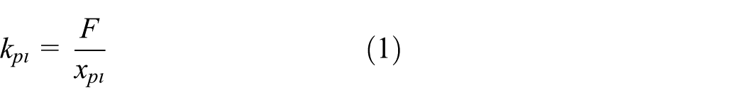

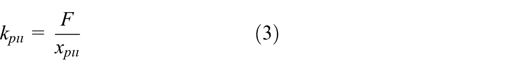

where


This study started with the creation of a 2D FEA of an asymmetric gear tooth to calculate the deflection values. Because more than 1200 analyses were planned to calculate the single tooth stiffness for a variety of tooth numbers and pressure angles, 2D models were preferred. Certainly, 3D models may be more reliable than the 2D models; however, the FEA running time of 2D models is less than 15 times that of 3D models for each analysis. Furthermore, in the FEM approach, if the model has a constant cross-sectional area, the 2D models result as accurate as the 3D models. The amount of error between the 2D and the 3D models is nearly 3%. To eliminate these differences in the study, correction factors for each case were substituted into the derived formulas. A computer program 1 was prepared using MATLAB. This program enables the researcher to change basic gear parameters, such as module, tooth number, pressure angle, face width, modulus of elasticity, and Poisson’s ratio. During the running process of MATLAB, a batch file was generated for ANSYS, and all FEM procedures from 2D modeling to post-processing were done automatically using the batch file. Finally, a text file including the deflection values of the nodes was produced; the nodal deflections could also be gained from the software interface. This process was repeated for each gear pair. The flowchart of the study is shown in Figure 1.

Flowchart of the study.
In this study, a 2D FEM of the asymmetric gear tooth profile was created for the FEA (Figure 2). First, a larger pressure angle for the drive side than the coast side was selected for the asymmetric tooth design, and then tooth stiffness and mesh stiffness were investigated, respectively. In the FEA, the loads were applied to six different locations of the tooth (Figure 3). For each contact point, the applied loads were chosen as 250 N to calculate the tooth deflection. In order to define the Hertzian part of the deflection at the point of loading, the size of the mesh structure near the point of loading was used as suggested by Coy and Chao. 28 The estimated curves for tooth stiffness were drawn with regard to the radius of the gears using the deflection values at the nodes according to the text file produced by the computer program.

2D FEM model of asymmetric teeth.

Load application points on asymmetric tooth profile: (a) αc = 20°, αd = 30°; (b) αc = 18°, αd = 26°; and (c) αc = 30°, αd = 20°.
Gear mesh stiffness
Gear mesh stiffness depends on the number of teeth in contact. As can be seen in Figure 4, the meshing process starts at point A, which is the addendum circle of the driven gear and terminates at point E, which is the addendum circle of the driver gear. During the meshing process of low contact ratio spur gears, in some locations (between BD), the single tooth pair is in contact; however, in some locations (between AB and DE), the double teeth pairs are in contact (Figure 4). Thus, the gear mesh stiffness constantly changes between single and double teeth pair zones.

Contact line of asymmetric gears.
The equivalent stiffness of meshing tooth pairs can be written as follows
First tooth pairs

Second tooth pairs

Here, the tooth pairs are considered as springs connected in series:
KI ≠ 0 and KII = 0 in single contact zone (between |BD|)
KI ≠ 0 and KII ≠ 0 in double contact zone (between |AB| and |DE|)
In the single tooth contact zone, the gear mesh stiffness is equal to KI because only one gear pair is in contact. In the double tooth contact zone, the gear mesh stiffness can be calculated as (KI + KII). Thus, the double tooth contact zone mesh stiffness values are higher than the single tooth contact zone. In Figure 4, it is illustrated with cord BD that as the pressure angle increased on the drive side of the asymmetric gear, the length of the single tooth contact zone also increased. Thus, the gear pair contact ratio decreased. To define the single and double tooth contact positions, the radii of the highest and lowest points of single tooth contact must be known. The radii of these points were defined by Colbourne. 29
The radius of the lowest point of single tooth contact is
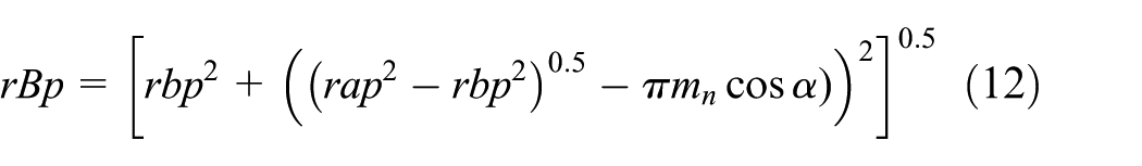
The radius of the highest point of single tooth contact is


The contact ratio can be calculated as

In general, the contact ratio is between 1.1 and 1.98 for gears with low contact ratio. The contact ratio should not be more than 1.98 for low contact ratio spur gears. The contact ratio of the gears directly defines the dynamic performance of the gear system. When the contact ratio increases, the dynamic performance of the gears also increases, but the vibration levels and noise decrease. The contact ratio also defines the load-sharing ratio and the number of teeth in contact. For instance, with the increment of the contact ratio, the number of teeth in contact changes; in low contact ratio gears, one gear pair is always in contact, but in high contact ratio gears, two gear pairs are always in contact. A diagram of a typical contact point, three mesh processes, and varying mesh stiffness is given in Figure 5 for low contact ration gears. As can be seen in the first position, two tooth pairs are in mesh in the region |AB|. When the gear reaches point B, the tooth pairs separate from each other, meaning that only one tooth pair is in contact in the region |BD|. Thus, the gear mesh stiffness decreases sharply. While the gear system is rotating, this process continues periodically as in Figure 5.

Changing of mesh stiffness in the gear meshing period.
Results and discussion
In this study, there were four different cases for each contact point. The deformation values and the tooth stiffness values were computed. In all cases, the number of teeth selected was between 20 and 60 for pinion and gear, and the module was 10 mm. In addition, different modules were used to test for accuracy, and the results of the different modules demonstrated a high degree of similarity. The pressure angle on the drive side (αd) and the pressure angle on the coast side (αc) were variables. In the first case, αd and αc were 20°–32° and 20°, respectively. In the second case, αd varied from 25° to 30°, and αc was held constant at 25°. In the third case, αd and αc were 20°–26° and 18°, respectively. In the fourth case, αd was held at 20° and αc varied from 20° to 30°. The gear data for each case are given in Table 1. When the pressure angle increases, the tip width of the gear decreases. Thus, the reduced tip width would be unsafe in practice as the tip is liable to be damaged easily, especially if the teeth are hardened.
Gear pairs’ properties of the cases.

Tooth stiffness calculation results
The primary purpose of this study was to develop a new method including some equations for calculating the tooth stiffness of spur gears with asymmetric teeth. A parametric study was conducted for this research with parameters of teeth number, and pressure angle on the coast side (αc) and drive side (αd). Four cases of asymmetric gear tooth stiffness were investigated for different contact points. The FEA results of the tooth stiffness of case 2 are given in Figure 6. By using the FEA results for each case, four different equations were developed. The new equation (19) was derived to estimate the tooth stiffness values of the spur gears

where
For case 1 (αc = 20° and αd = 20° … 32°)


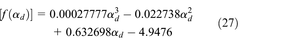
For case 2 (αc = 25° and αd = 25° … 30°)


For case 3 (αc = 18° and αd = 20° … 26°)


For case 4 (αc = 20° … 30° and αd = 20°)


FEA results of the tooth stiffness for contact points of case 2.
Four cases were investigated in this study, and the tooth stiffness results of case 2 are given in Tables 2–7. The results show that both the pressure angle on the drive side and the number of teeth affect the single tooth stiffness, depending on the contact points. The number of teeth increased from 20 to 60, and the pressure angle increased from 25° to 30°. This process was repeated for different modules. Consequently, in this study, 1200 cases were analyzed and 7200 displacement values were gained from the FEA.
Tooth stiffness FEA results for case 2 point-1 (N/mm).

Tooth stiffness FEA results for case 2 point-2 (N/mm).

Tooth stiffness FEA results for case 2 point-3 (N/mm).

Tooth stiffness FEA results for case 2 point-4 (N/mm).

Tooth stiffness FEA results for case 2 point-5 (N/mm).

Tooth stiffness FEA results for case 2 point-6 (N/mm).

Figure 7 shows the effect of the drive-side pressure angle on the single tooth stiffness, as calculated according to the tooth stiffness results. A correlation was found between the drive-side pressure angle and the single tooth stiffness of the gear. The average increase in the stiffness was found to be 10% when the pressure angle was 25°. When the drive-side pressure angle reached 32°, the single tooth stiffness increased by nearly 20%.

Pressure angle effects on the single tooth stiffness (module = 3.18 mm, Z = 20, b = 25.4 mm).
In this study, in order to verify the results obtained from FEA, the results were compared with the findings in the literature.16,17 The FEA results and Kuang et al.’s16,17 equations, which are well known in the literature, were compared. First, the single tooth stiffness results were compared. As can be seen in Figure 8, both the results from the literature and FE analysis matched well.
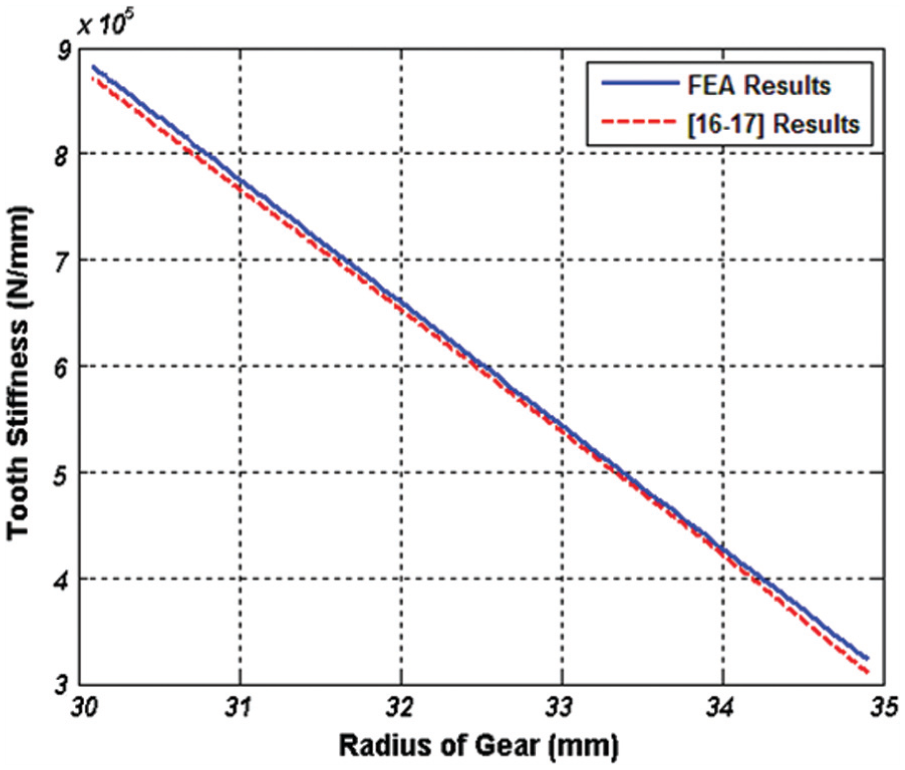
Comparison of single tooth stiffness by using different methods (module = 3.18 mm, αd = αc = 20°, Z = 20, b = 25.4 mm).
Second, time-varying mesh stiffness results were compared. The comparison of FE analysis results and Kuang et al.’s results16,17 is given in Figure 9. The differences between the two methods are acceptable. Thus, it can be said that the FE analysis procedure can be used for the definition of gear mesh stiffness.

Comparison of mesh stiffness by using different methods (module = 3.18 mm, αd = αc = 20°, Z = 20, b = 25.4 mm).
Mesh stiffness calculation results
After tooth stiffness values were obtained from ANSYS, the mesh stiffness was calculated using equations (10) and (11). In the condition of single tooth contact, the mesh stiffness is directly equal to
Gears with asymmetric teeth for which the coast-side angle was constant at 20° and drive-side angle varied from 20° to 32° were investigated in terms of gear mesh stiffness in case 1. The drive-side pressure angle was found to be an effective parameter on the mesh stiffness. When the gear drive-side pressure angle increased, the root of the gear also increased; thus, the single gear tooth stiffness increased. When the tooth pressure angle on the drive side was higher than 20°, it became stiffer than the symmetric gear. When the gear pressure angle increased, the contact stiffness increased gradually. In Figure 10, three different gear pairs are given. When the drive-side pressure angle increased, both the single and the double zone mesh stiffnesses increased. Furthermore, the double contact zones become shorter and the single tooth contact zone becomes larger. This means that the contact ratio was also affected by the drive-side pressure angle. When the drive-side pressure angle increased, the contact ratio decreased.

Effect of drive-side pressure angle on gear mesh stiffness for case 1 (αc = 20°, αd = 20°–25°–32°).
Gears with asymmetric teeth for which the coast-side angle was held constant at 25° and the drive-side angle varied from 25° to 30°were investigated in terms of gear mesh stiffness in case 2. This type of gear is especially used in the United States. The mesh stiffness variations of the gears were obtained from the enhanced equation (20). In this case, the results were similar to case 1. When the drive-side pressure angle increased, the mesh stiffness of the gears also increased (Figure 11), although not as much as in case 1, because the reference gear pairs (αc = 25°, αd = 25°) in case 2 were stiffer than the reference gear pairs (αc = 20°, αd = 20°) in case 1. Also, in case 2, it was clearly seen that the augmentation of the drive-side pressure angle reduced the gear contact ratio.

Effect of drive-side pressure angle on gear mesh stiffness for case 2 (αc = 25°, αd = 25°–28°–30°).
In case 3, a different type of gear pair was investigated. Both coast-side and drive-side pressure angles (αc, αd) were the smallest gear type in this study. Thus, the lowest stiffness values were gained in case 3. However, the characteristics of the mesh stiffness were the same as in the other cases, in which the mesh stiffness of the gear pair increased when the drive-side pressure angle increased. The amount with which the mesh stiffness increased according to the drive-side pressure angle was greatest in case 3 (Figure 12).

Effect of drive-side pressure angle on gear mesh stiffness for case 3 (αc = 18°, αd = 20°–24°–26°).
Case 4 is similar to case 1 but the coast-side pressure angle (αc) increased from 20° to 30° and the drive-side pressure angle (αd) was held constant at 20°. In this case, the effect of the coast side on the mesh stiffness was investigated. The results were also similar to case 1 but with slight differences. In Figure 13, the mesh stiffness of the gear pairs could be seen. When the coast-side pressure angle increased, the mesh stiffness also increased, although not as much as in case 1. Moreover, the contact ratio decreased when the coast-side pressure angle increased. The increased stiffness and low contact ratio lead to an increase in dynamic force.

Effect of coast-side pressure angle on gear mesh stiffness for case 4 (αc = 20°–25°–30°, αd = 20°).
Conclusion
The primary aim of this study was to define the single tooth stiffness and gear pair mesh stiffness for different types of spur gears with asymmetric teeth. First, the single tooth stiffness calculation method was defined using MATLAB based on 2D FEA models for four different cases. In each case, different drive-side and coast-side pressure angles were investigated, and for each contact point, the tooth stiffness values were calculated. Based on the FEA results, new empirical correlations were developed for single tooth stiffness using multiple regression methods. Second, the gear mesh stiffness values were calculated using the tooth stiffness results obtained for each of the four different cases.
Based on the findings of this study, the tooth stiffness and the mesh stiffness values of the asymmetric gears indicate that FEA results and empirical equation results are compatible with each other, with an acceptable margin of error of 5% between the FEA and the equations results. For the asymmetric teeth, when the pressure angle increased (drive side or coast side) due to an increase in the tooth thickness of any radius, the single tooth stiffness increased slightly. Consequently, the gear mesh stiffness increased. Also, the pressure angle affected the contact ratio of the gear pair, which decreased as the pressure angle increased because the single tooth contact length increased as the pressure angle on the drive side increased. The results obtained from this study may provide important input for designers. Because the dynamic gear loads are affected by mesh stiffness, designers may use the mesh and tooth stiffness results for the dynamic analysis of gears with asymmetric teeth.
Footnotes
Appendix 1
Academic Editor: Yi Wang
Declaration of conflicting interests
The author(s) declared no potential conflicts of interest with respect to the research, authorship, and/or publication of this article.
Funding
The author(s) disclosed receipt of the following financial support for the research, authorship, and/or publication of this article: This study was supported in part by Uludağ University (The Scientific Research Project; project no: OUAP (MH)-2014/25).