
Abstract
Due to the complex structure of the planetary gear train, the influence of early fault on the dynamic characteristics of the planetary gear train is complex and changeable. This paper proposes a time-varying meshing stiffness (TVMS) calculation model of internal meshing considering the coupling effect between teeth; and a multi-tooth coupling stiffness calculation model of the planetary gear train. The Archard equation is used to calculate the wear depth; moreover, the potential energy method calculated The TVMS of the planetary gear train under the wear state. The wear fault will cause the TVMS of the gear to decrease. In the two-stage planetary gear train, the TVMS of the first-stage sun-planet gear decreases more obviously. In addition, there is a specific coupling effect between the sun, ring, and planetary gear. The influence of the wear fault on the two-stage planetary gear train is analyzed by calculating the synthetic stiffness considering the meshing phase difference. The results show that under the same wear fault condition, the more teeth involved in meshing, the more significant the decrease in coupling stiffness.
Introduction
Planetary reducers have many advantages, such as small size, high carrying capacity, and stable operation, which are used in engineering, medical, aerospace, and other fields.1,2 The planetary reducer is shown in Figure 1, due to the complex internal structure and the simultaneous engagement of multiple points, there are technical difficulties in the fault diagnosis and dynamic characteristic evaluation of planetary gear train. 3 The TVMS is the main excitation of gear dynamics. Therefore, the calculation and analysis of TVMS for early failures can effectively promote the research of gear fault identification and life prediction. 4
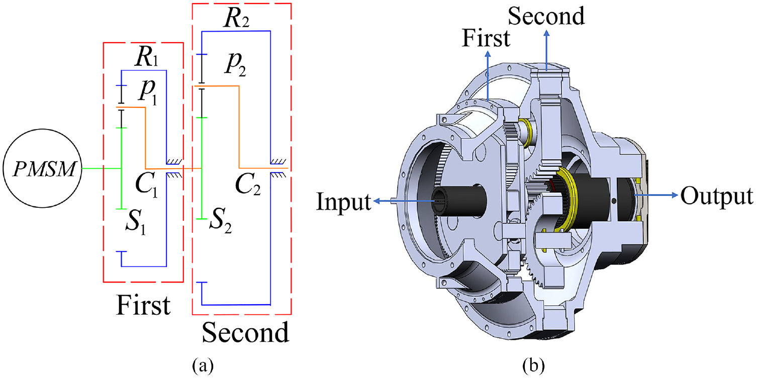
Two-stage planetary gear train: (a) schematic diagram of the structure and (b) 3D model.
The early fault of tooth surface wear causes noise. It reduces the stability of gear transmission and the overall performance of mechanical equipment. Studying the changes in mesh stiffness caused by wear can provide the basis for identifying and diagnosing wear faults.5,6 The potential energy as a theoretical basis for calculating gear meshing stiffness, this method solves many practical scientific research problems.7,8 Shen et al. 9 Analyzed the TVMS of planetary gear train considering the wear and improved the traditional calculation model of TVMS. Chen et al. 10 Calculated the TVMS of cracked gear. A computational model of gear crack is proposed and studied and analyzes the dynamic behavior caused by gear crack. The research showed that the crack fault would decrease TVMS, and its dynamic behavior was characterized by impact. Ma et al. 11 Analyzed the transition fillet area, and the calculation method of TVMS is corrected. At the same time, the external mesh stiffness was divided into two calculation models, and the rationality was verified by the finite element method. Mo et al.12–16 Analyze the dynamic behavior of the gear drivetrain, which explains the causes of the change in dynamic behavior. Liang et al. 17 Calculated the TVMS of gear pitting, and the effect of different pitting degrees on TVMS was studied. Wu et al. 18 Researched the vibration effect of gear crack on the first-stage gear transmission system. By comparing the statistical indicators, their vibration characteristics were summarized. Yuksel and Kahraman 19 Characteristic analysis of gear wear failures, the dynamic behavior of tooth separation in planetary gear train is nonlinear. The tooth surface wear significantly changes the non-resonant velocity, and the tooth separation will weaken near the resonant peak.
The TVMS of gear is an important parameter of fault dynamics, and the accurate solution of TVMS is of great significance for solving the dynamic behavior caused by early faults. Tian 20 Corrected the calculation method of gear meshing stiffness. By considering shear deformations, proposing a new method for calculating TVMS. Sainsot et al. 21 Found the gear body will also produce a certain degree of deformation during the meshing process. He analyzed the deformation caused by the load on the gear. He proposed the calculation formula of the gear body deformation. However, the error of Sainsot’s research on the deformation of the double teeth meshing zone is always large. So the solution to the basal body deformation of the double-teeth toothing region has become a very challenging problem. In 2018, Xie et al.22,23 Proposed a flexible base stiffness calculation principle considering the coupling effect between teeth. The calculation accuracy is further improved. Chen et al. 24 Proposed a nonlinear principle of contact stiffness calculation.
The precise calculation of the TVMS is still an area of exploration by many scholars, particularly the calculation of fault meshing stiffness for complex gear trains. In this paper, An improved TVMS model of planetary gear train is proposed, considering the coupling effect between teeth and the Hertzian contact stiffness under nonlinear load. At the same time, TVMS wiht wear is calculated, and the changes in mesh stiffness of early gear failures were quantitatively analyzed. Finally, the spring oscillator model of sun-planet-ring gears is established, and synthetic stiffness is calculated by using the principle of series, which significantly simplifies the complex gear train dynamics model.
At the same time, due to the planetary gear train in the installation, there is a certain phase difference between each planet gear. When analyzing the effect of wear on the TVMS of a two-stage planetary gear train, we consider the coupling effect of the phase difference between each planet gear and wear on the TVMS of the planetary gear train.
TVMS calculation model
The flowchart for calculating the TVMS is shown in the Figure 2. By analyzing the geometric motion relationship of the gears, the calculation formula of TVMS is derived. The TVMS of the gear is then calculated according to the parameters.
Flow chart for calculating the TVMS.
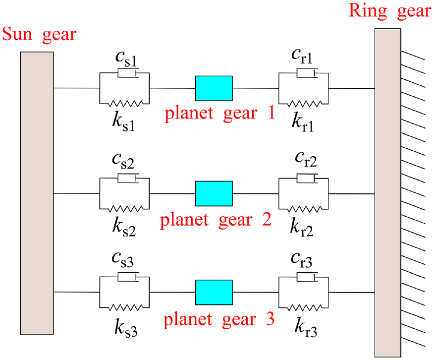
In Figure 3, the ring of teeth is not rotating, and each stage has three planet gears. There are two types of meshing in the transmission system; therefore, in the study of the TVMS, the two kinds of meshing need to be modeled and calculated respectively.
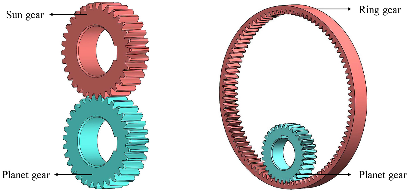
Two meshing forms.
TVMS calculation model of external
Five kinds of deformation stiffness can express the TVMS of gear. They are Hertzian stiffness kh, Flexible base stiffness kf, Shear stiffness ks, Bending stiffness kb, and Axial compression stiffness ka. There are two cases of inconsistent relationship between the base radius and the root fillet radius in gear external engagement. However, kb, ks, and ka relate to gear geometry parameters, so the kinematic relationships and geometric positions of the gears during the meshing process need to be analyzed, the case-by-case calculation and analysis. Firstly, the case that the root fillet radius is smaller than the base radius is analyzed.
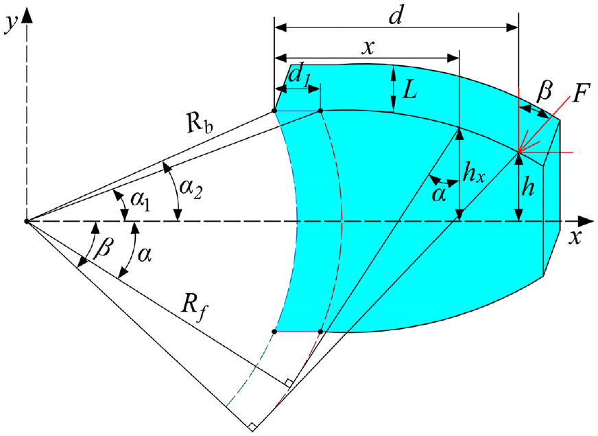
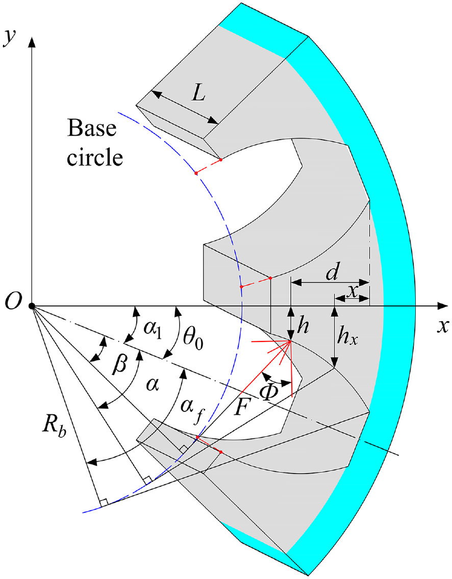
In Figure 4, rf is the root fillet radius; d is the horizontal distance from the contact point on the tooth surface to the root circle; β is the angle between the contact load and the y-axis; hx is the distance from the gear mesh point to the tooth midline; α1 and α2 are The tooth half angle corresponding to the base circle, and the root circle is respectively. Ax and Ix are important parameters for calculating gear deformation. The geometric parameters of the gears are the key to deriving the formula of the TVMS.


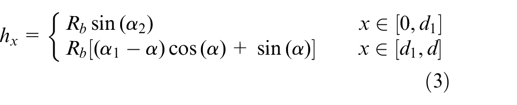

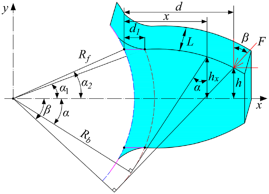
Gear tooth profile with root circle less than base circle.
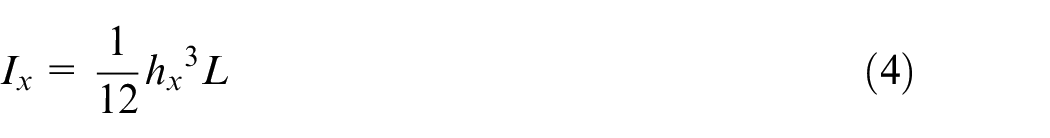
According to the geometric movement and gear parameters, which is regarded as a beam structure, the calculation formula of the flexible stiffness is as follows.
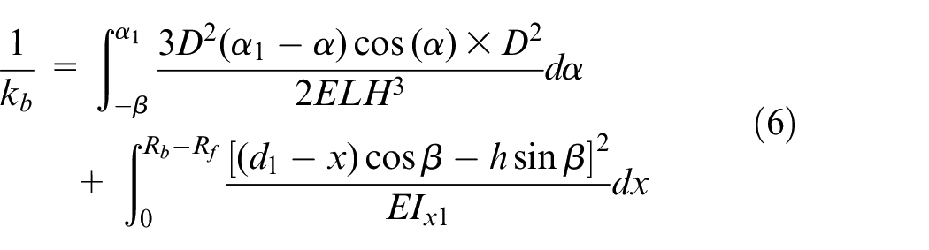
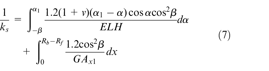
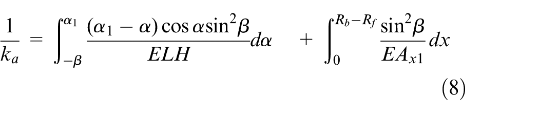
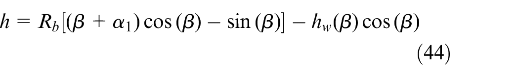
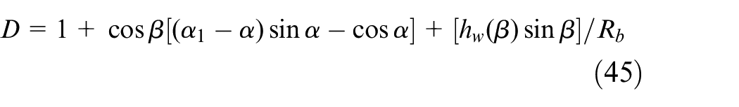
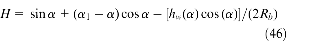
E is elastic modulus; L is tooth width; v is Poisson’s ratio; D and H are functions related to gear geometric parameters; they are shown below.


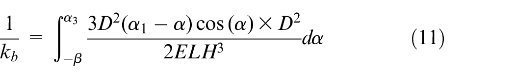
When the number of teeth exceeds 41, the geometric position relationship of the parameters of the gear changes.
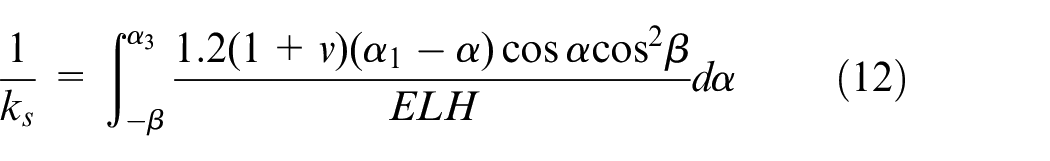
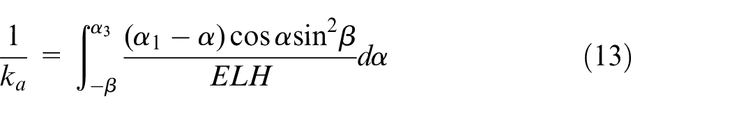
When the root fillet radius is greater than the radius of the base circle, the number of teeth at this time is less than 41. Compared with the previous case, the gear tooth profile as a whole becomes smaller, and the parameters in the stiffness are redefined according to the geometric relationship in Figure 5. The calculation formula for stiffness is as follows.
Gear tooth profile with root circle greater than base circle.
D and H is a function related to geometric parameters of gear. In the traditional meshing stiffness calculation model, the Hertz contact model is generally used to calculate the contact stiffness, and the stiffness is constant. The load and deformation of the gear in the meshing process are variable, so the contact stiffness is not constant. And, the contact stiffness of gear should be redefined in the traditional model. We should take this factor into account in the traditional model. When the actual contact load of the gear is calculated, the contact stiffness can be expressed as.
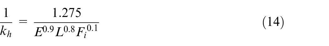
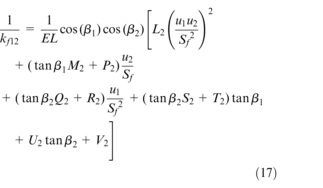
Fi is the contact force in engagement. An important part of gear meshing stiffness is only one tooth in the single tooth meshing area. According to Sainsot’s research, the flexible base stiffness can be expressed as.
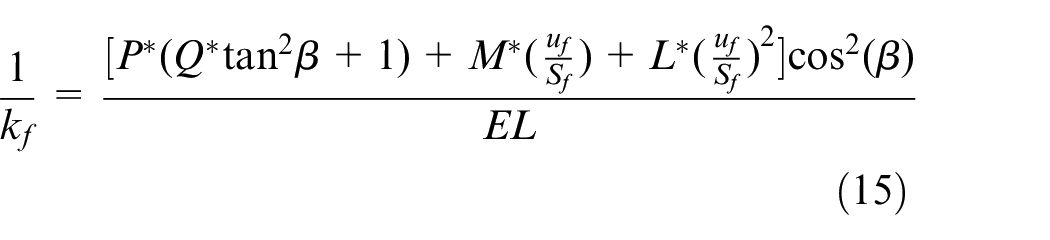
In the equation (17), uf = Rb/cos(β)-Rf, Sf is the tooth root arc length Sf = 2θfRf, θf is half of the tooth root arc corresponding to the center angle, hf = rf /rint, rint is the hub radius, rf is the tooth root radius, P*, Q*, M*, L* can be seen by Chen et al. 10 There are two or more teeth loaded at the same time during gear meshing, so the coupling between teeth cannot be ignored, the equation (15) is not applicable.
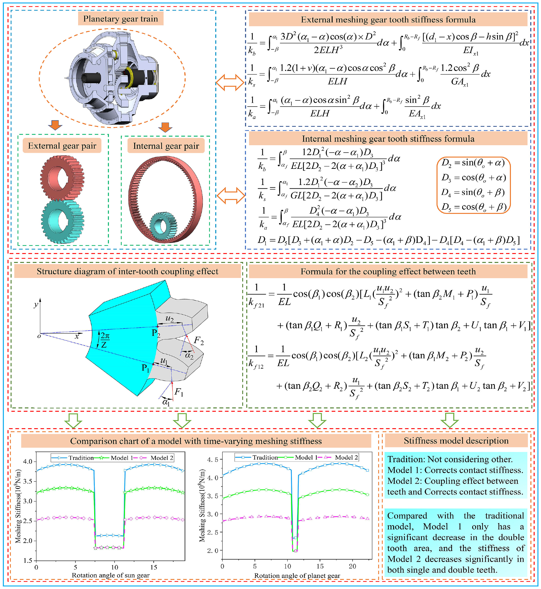
Figures 6 and 7 show that when two teeth are involved in meshing, the coupling effect will cause the adjacent teeth to deform. In Xie et al., 23 the structural coupling effect of spur gear external engagement has been studied, and the flexible base stiffness calculation formula considering the structural coupling effect of external engagement is derived by the induced deformation formula, such as equations (18) and (19).
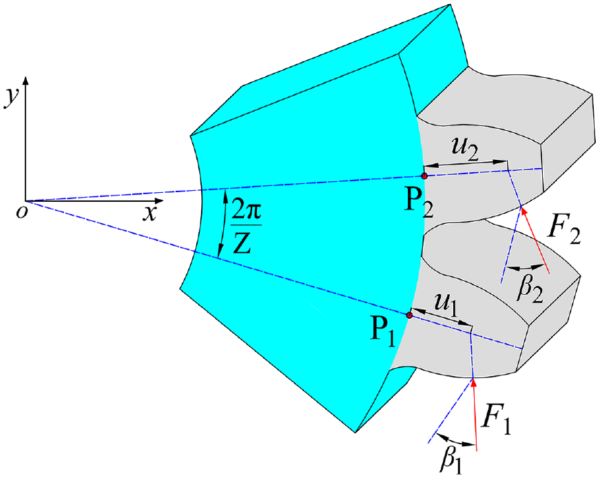
Model of the coupling effect of external meshing between teeth.
Structure diagram of inter-tooth coupling effect.
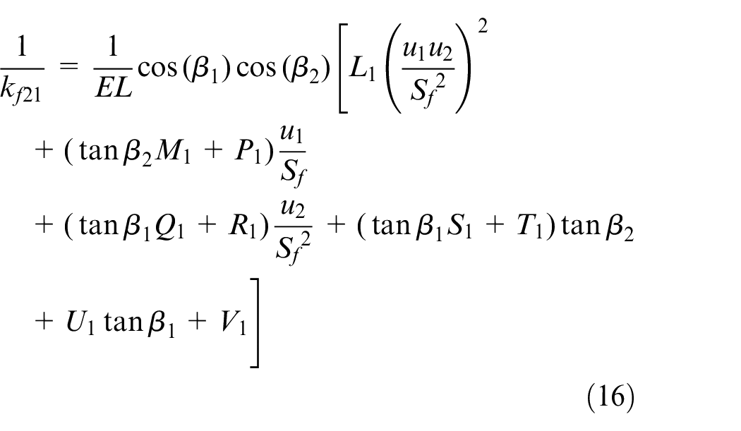
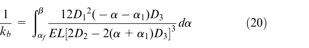
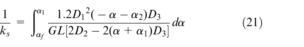
The expressions ui and βi (i = 1, 2) with uf and β in equation (17) have the same meaning, and the values of Li, Mi, Pi, and Qi (i = 1, 2) can be calculated by equation (20) and Si, Ti, Ui, and Vi by equation (21).
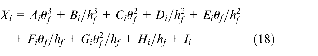
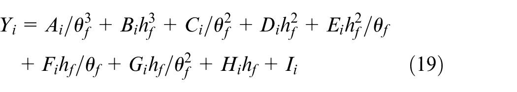
Xi represents Li, Mi, Pi, and Qi, Yi represents Si, Ti, Ui, and Vi. and rf is the tooth root fillet radius. Other parameters of equations (20) and (21) in Xie et al. 22
TVMS calculation model of internal
Gear transmission transmits power and motion through the meshing between the teeth of two gears; planet gear is involved in internal meshing. And the planet gear is generally machined by the tooth on the outer gear surface, while gear rings are machined on the inner surface. The structural parameters of ring gear differ from sun or planet gear. The geometric parameters of the ring gear are shown in Figure 8.
Internal gear tooth profile.
In section 2.1, the TVMS of spur gear external engagement is calculated and analyzed, and the meshing stiffness calculation principle of internal engagement and external engagement is roughly the same.
In the form D2 = sin(θ0+α), D3 = cos(θ0+α), D4 = sin(θ0+β), D = cos(θ0+β). The contact stiffness and flexible base stiffness of internal engagement are similar to those of external engagement.
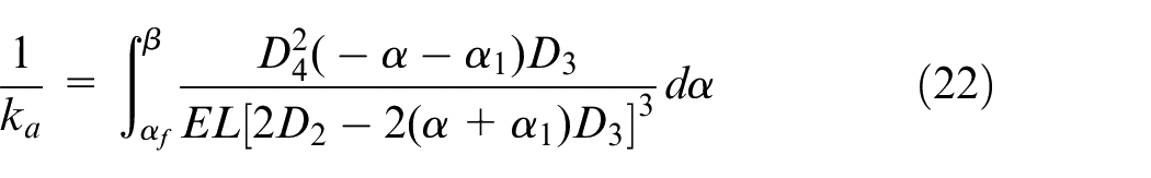
The flexible base stiffness is calculated by the same method. The geometric parameters of the coupling effect between teeth of internal meshing are shown in Figure 9.
Model of the coupling effect of internal meshing between teeth.
The structural coupling effect of internal gear engagement can be calculated according to the derivation principle of the external engagement coupling effect. The calculation formula of the coupling effect between teeth is derived according to the geometric parameters of internal meshing. Based on the study of the coupling effect of external meshing structure, the induced deformation formula of internal meshing P2 is shown as follows.
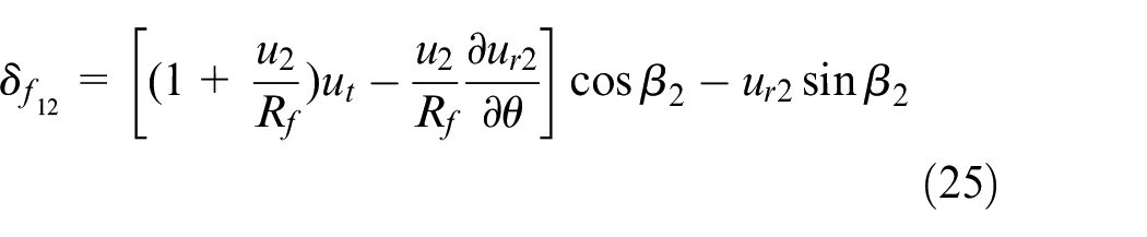
δ f12 is the deformation of tooth 2; θ is the tooth root circular arc function, its value range is [−θf, θf]; ut and ur2 are the displacement component of P2; u2 is shown in Figure 9; ut and ur2 based on the study of gear stress-displacement in Sainsot et al., 21 substitute it in equation (25).
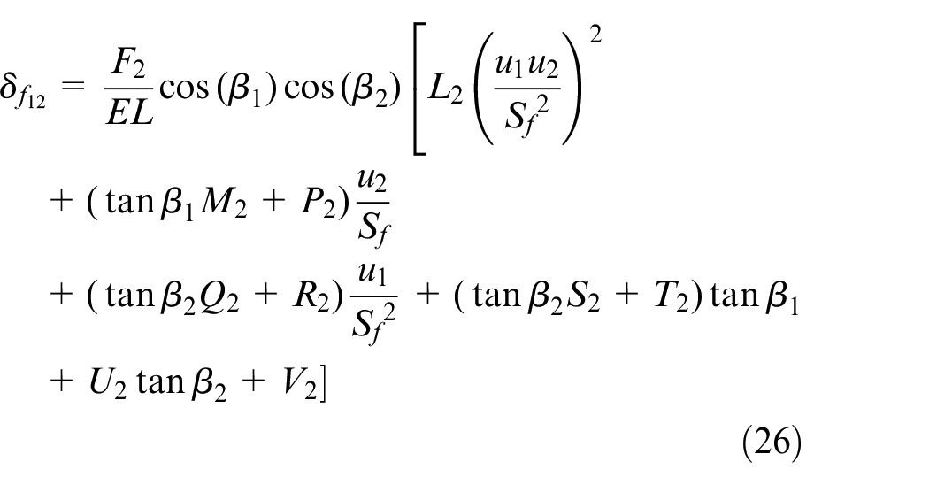
The specific expressions of Li, Mi, Pi, Qi, Si, Ti, Ui, and Vi are in Xie et al. 23
The principle of the interdental effect of internal meshing is consistent with that of external meshing. So, the deduced calculation formula is consistent, but the geometric parameters of internal meshing are inconsistent with other calculation parameters. The geometric parameters of an internal surface gear in Figure 9.
Calculation of TVMS
The TVMS is able to reflect the failures that occur during the gear transmission process. The calculation formula of TVMS considering the coupling effect between teeth is as follows.
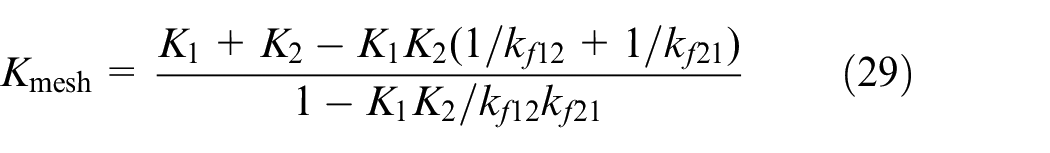
Kmesh is the TVMS with an inter-tooth coupling effect in the double-tooth meshing area. When only one pair of teeth participate in the meshing in the tooth meshing area, there is no coupling effect. So the stiffness of the single tooth area is Calculation Based on equation (15).
The traditional model does not consider the contact stiffness and the coupling effect between teeth under nonlinear loads. Model 1 considers the contact stiffness under nonlinear load, and Model 2 considers the contact stiffness and the coupling effect between teeth under nonlinear load.
The traditional model of TVMS of internal meshing is improved. The contact stiffness is modified, and the coupling effect is considered in the model of TVMS. As shown in Figure 10, When both teeth are involved in meshing, the Coupling effect between teeth reduces TVMS. In the single tooth area, only one tooth participates in meshing; there is no inter-teeth coupling effect.
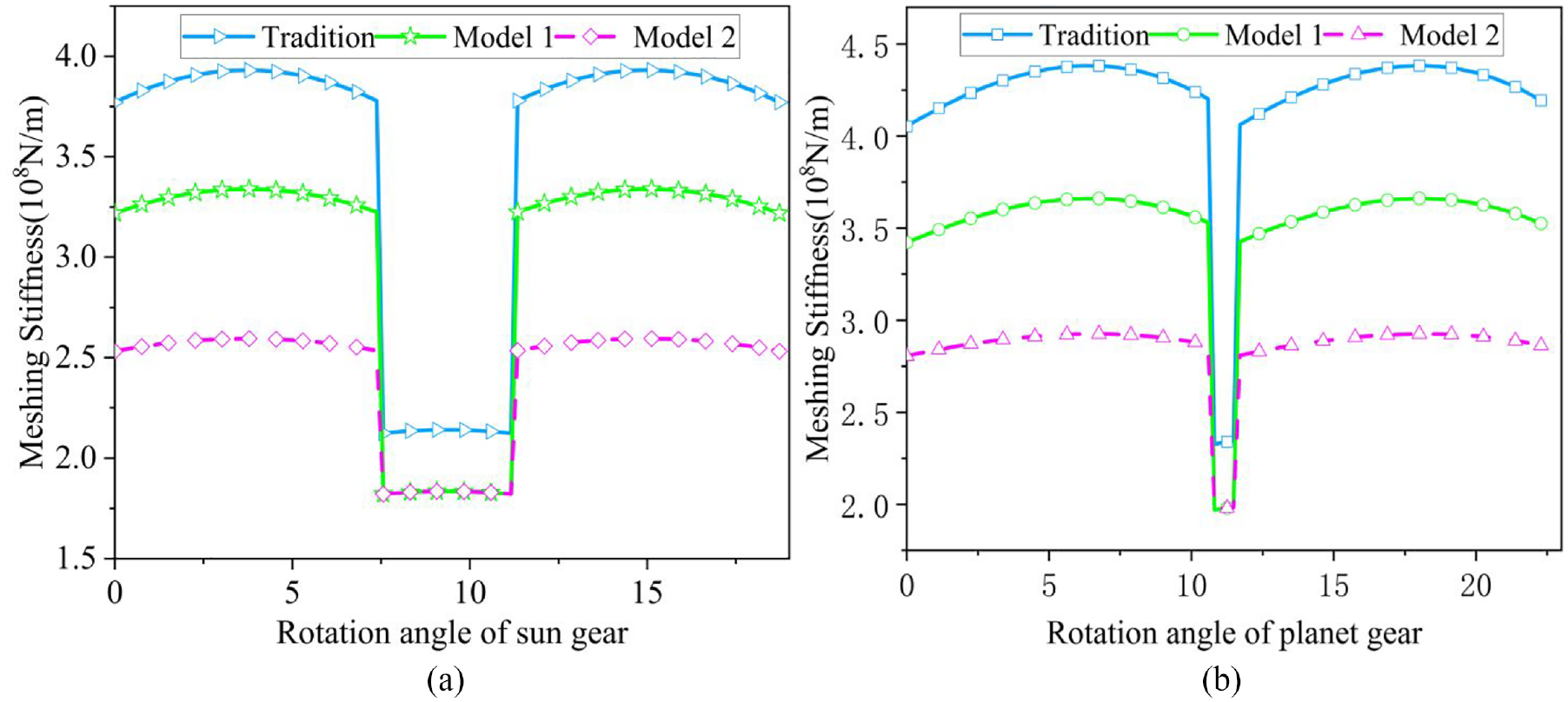
TVMS of gear internal engagement: (a) external mesh and (b) internal mesh.
Wear depth of planetary gear train
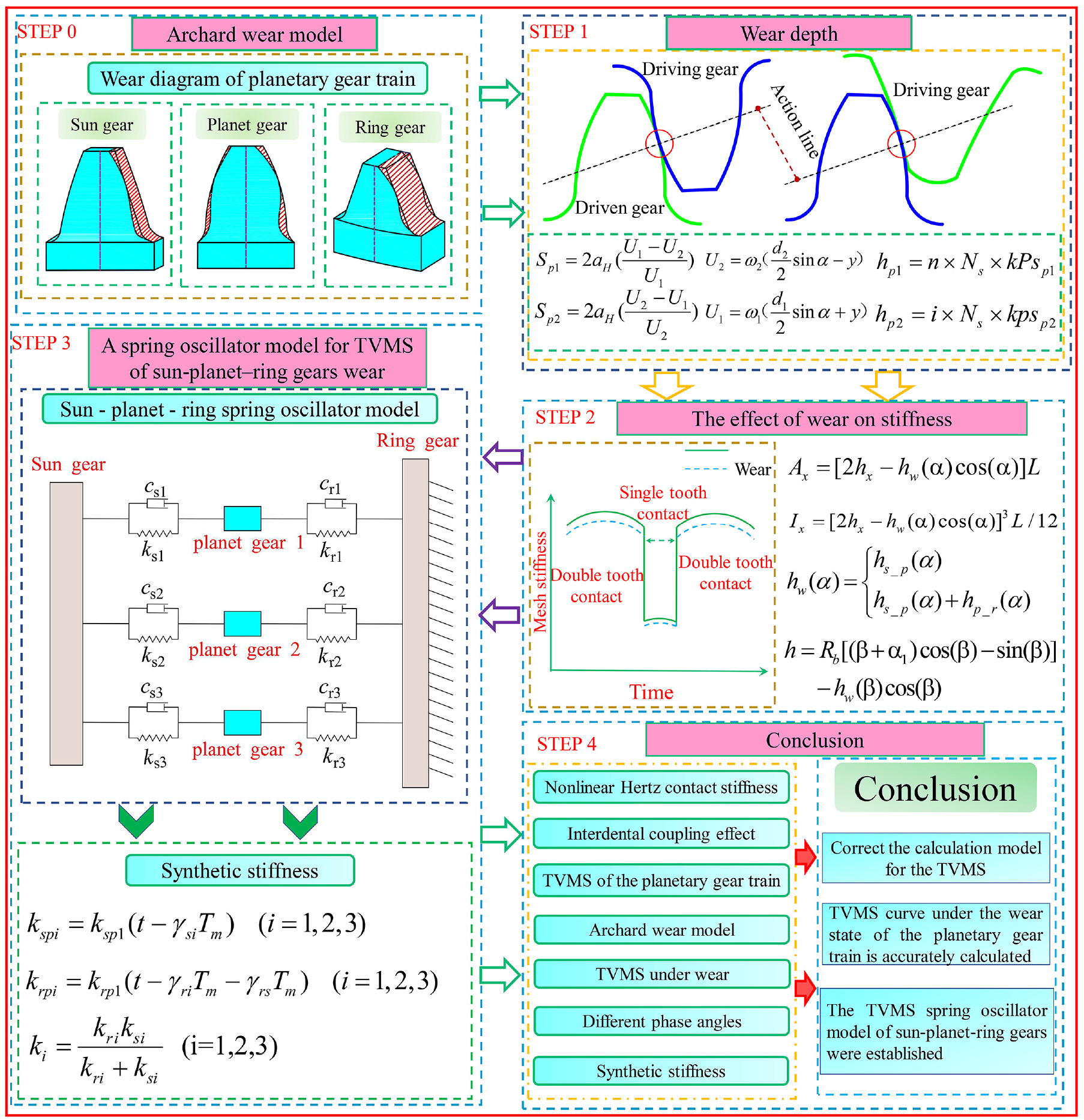
The long-term operation of the two-stage planetary gear train under high load causes the instantaneous velocity to be inconsistent, which makes the meshing point slip relatively. Under the action of tooth surface contact load, tooth surface wear occurs, which affects the mechanical performance. In this paper, cite the classical Archard wear model. Wear occurs on the working surface of the sun and ring gear; however, the other side assumes no wear. However, planet gear has two working surfaces producing wear, and the wear of the two working surfaces is inconsistent.
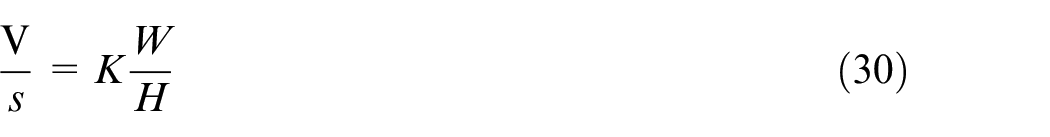
The calculation process for synthetic stiffness in the Figure 11. The calculation of the synthetic stiffness with wear conditions is beneficial to simplify the modeling of the multi-stage gear train. Wear is unevenly distributed on the surface of the tooth profile, and the classical Archard wear calculation formula is as follows.
Flow chart for calculating the synthetic stiffness.
V is volume of the wear material; S is the relative gliding distance of the contact surface; K is dimensionless wear coefficient; W is contact surface load; H is material hardness of the contact surface. In the process of gear work. The wear calculation formula for the gear is as follows.

h is wear depth; sp is relative slip displacement of point P from meshing in to meshing out; p is the pressure at the contact point. Since the wear depth is related to the number of meshes, the wear situation before and after each mesh is inconsistent, but it maintains a certain relationship, and a progressive relationship can be taken to calculate the wear depth. The detailed derivation is as follows.
The distance between the meshing points in the sun-planet gears.
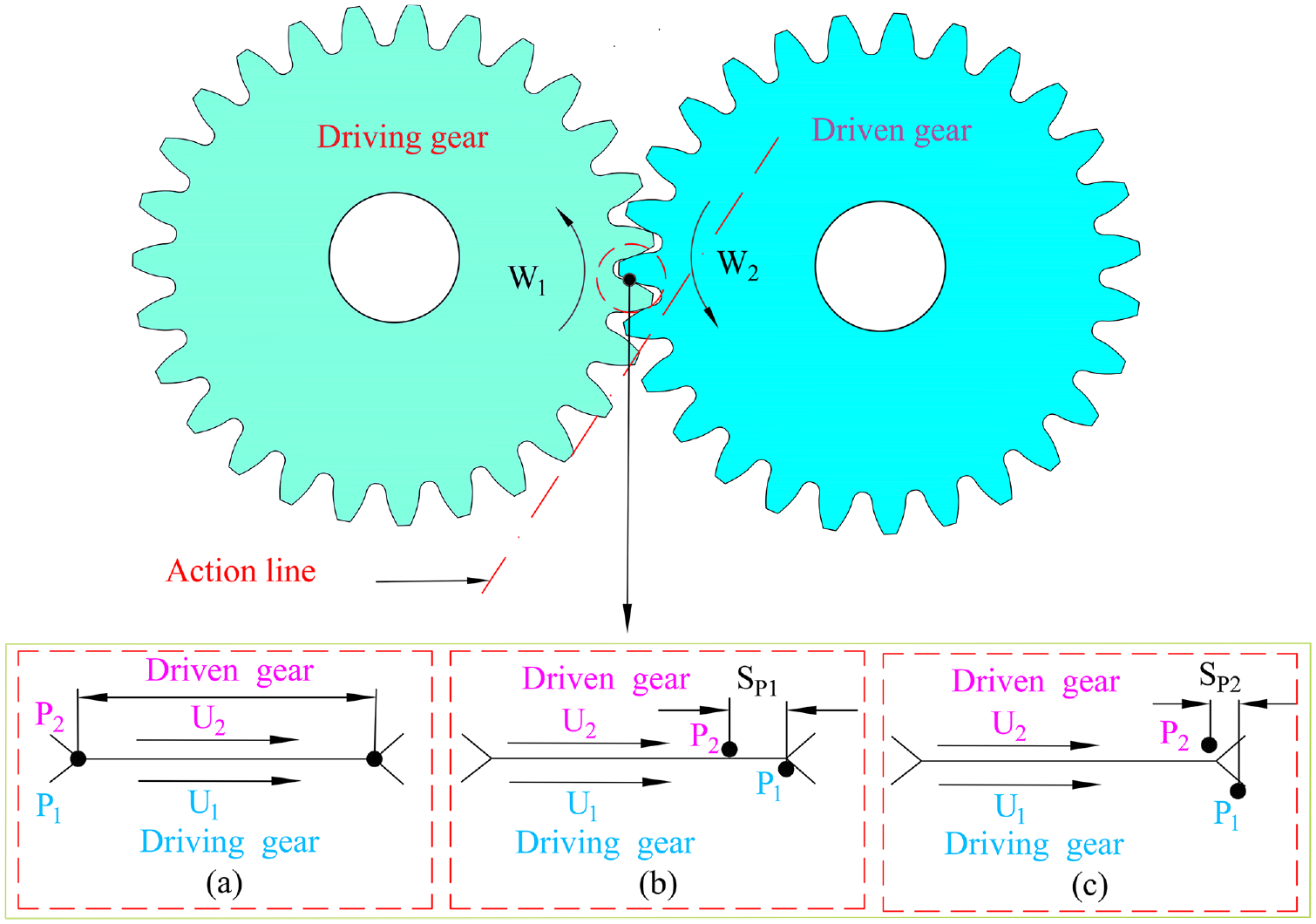
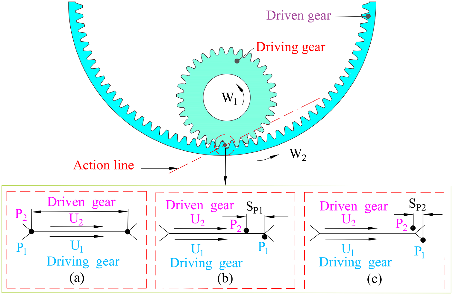
There are three different positional relationships between the active gear and the driven gear shown in Figure 12. The displacement of two meshing positions is 2aH. When the master follower is involved in the meshing, there may be an error due to the speed of the two gear meshing points. So, the distances between points P1 and P2 moving along the contact line are inconsistent. So the relative sliding displacements of P1 and P2 can be expressed as.
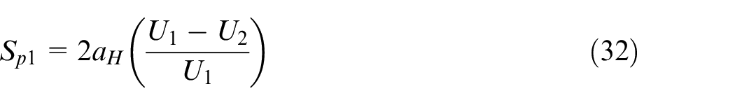
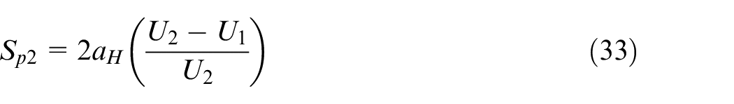
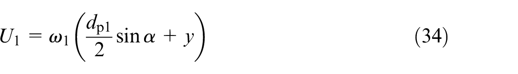
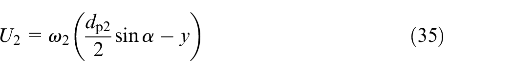
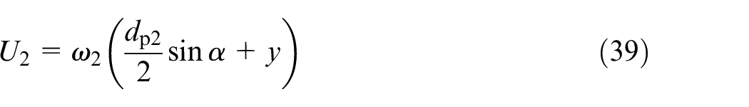
aH is the contact half width; U1 and U2 are the speeds of meshing points P1 and P2; w1 and w2 are angular velocities; dp1 and dp2 are the pitch circle diameter of the active and driven gears; α is pressure angle; The difference in relative speed leads to the sliding displacement being the main cause of wear.


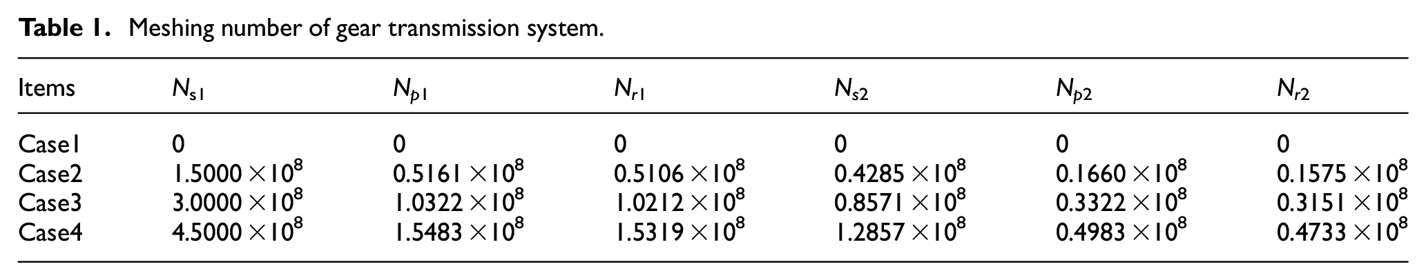
In equations (45) and (46); z is the teeth amount of gear. subscript s indicates the sun gear, and subscript p represents planet gear. n is the amount of planet gears; N is the amount of engagements. Sun gear engages with multiple planet gears, so the engagement times should be nNs. However the planet gear should be (Z1/Z2)Ns.
The sun gear is engaged with multiple planet gears, Therefore, the wear of the sun gear is more serious than the planet gear, but the planet gear is also involved in the wear of the ring gear.
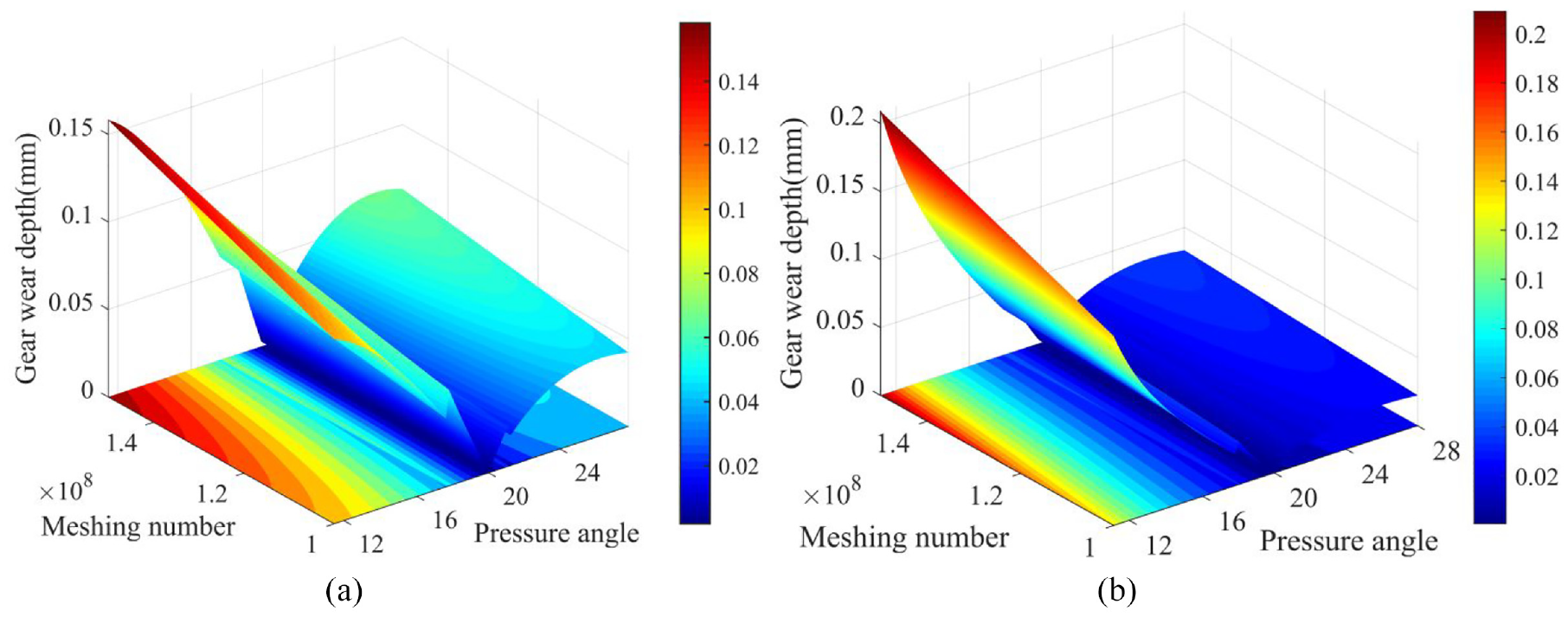
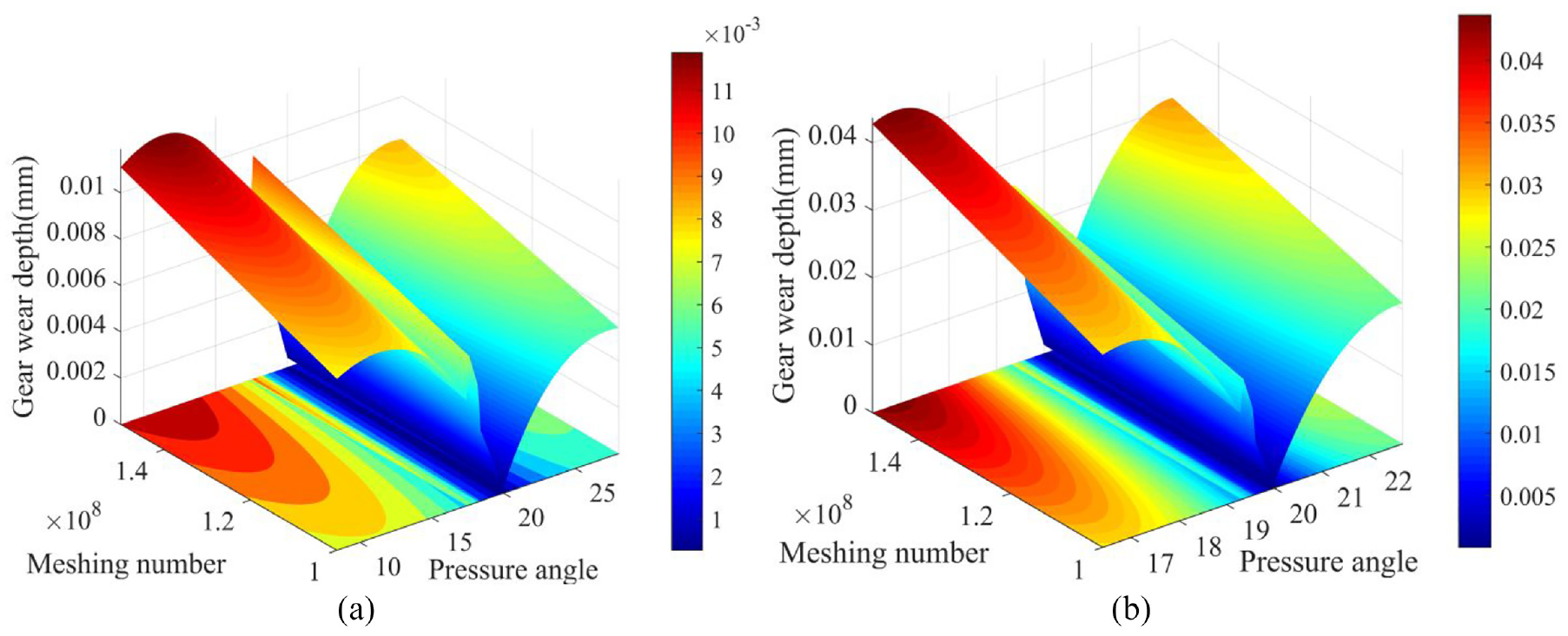
The wear depth of the external meshing: (a) sun gear wear situation and (b) planet gear wear situation.
The calculation principle of the wear depth of the internal meshing is consistent with that of sun-planet gear. The difference lies in the difference of motion relationship and geometric position, which leads to the change of Hertzian contact stiffness and depth of meshing point.

The parameters in the formula have the same meaning as those in the calculation formula of sun gear-planet gear. The ring gear is also engaged with multiple planet gears at the same time, and the calculation formula for the actual number of meshes is as follows
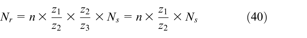
Nr is the engagement amount of ring gear. Although the ring of gear is meshed with the three planet gears, the wear of the ring of gear is not very serious due to the large amount of teeth of the ring of gear, The wear depth of the internal meshing is shown in Figure 14.
The distance between the meshing points in the planet-ring gears.
As shown in Figures 13 and 15, the wear depth of the contact surface between the external meshing sun gear and the planet gear is larger than that of the contact surface between the internal meshing planetary gear and the ring gear. So, the external meshing of the planetary gear train is more prone to tooth surface wear failure.
The wear depth of the internal meshing: (a) planet gear wear situation and (b) ring gear wear situation.
TVMS of the planetary gear train considering wear
Gear wear can deform the gear profile, causing the TVMS to change. In the second section, establish a computing model for TVMS. In the third section, the gear wear is analyzed and the wear depth is calculated. This section will build a model of TVMS calculations that consider wear. Number of gear engagements shown in Table 1.
Meshing number of gear transmission system.
The TVMS of sun-planet gears with wear
This is evident from the content of section 3. The wear of planet gear on both sides, and the wear of sun gear out only one side. Therefore, when calculating the TVMS of wear, the wear of planet gear situation should be calculated separately. The formula for calculating the wear depth of external meshing is as follows.
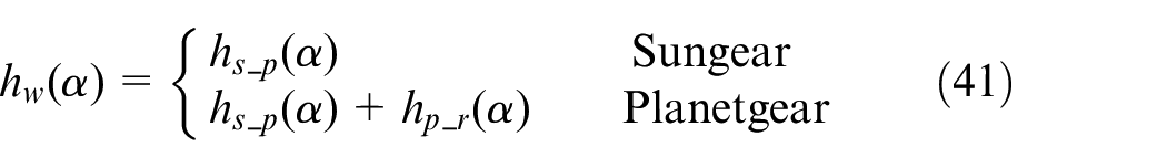
The tooth surface wear depth is the same as the tooth surface contact load direction, so wear should be projected parallel to the tooth thickness direction. Considering the TVMS of gear wear, the change of section inertia moment and section area should also be analyzed. It is expressed as follows.


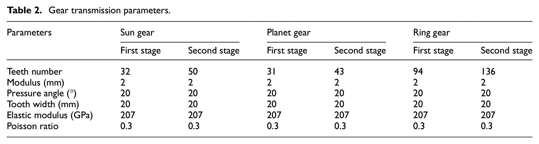
According to the above geometric parameters Ix, Ax, h, D, and H, the calculation model of external meshing TVMS in Section 2.1 is substituted to obtain the TVMS of sun-planet gears wear. The external meshing is divided into two models; the parameters for both models are shown in Table 2. Because the paper uses a planetary reducer as the object, the number of gear meshes closer to the output is relatively small. When calculating the TVMS of the sun-planet gears with wear condition, it should take into account the real wear of the planet gear, that is, wear on both sides.
Gear transmission parameters.
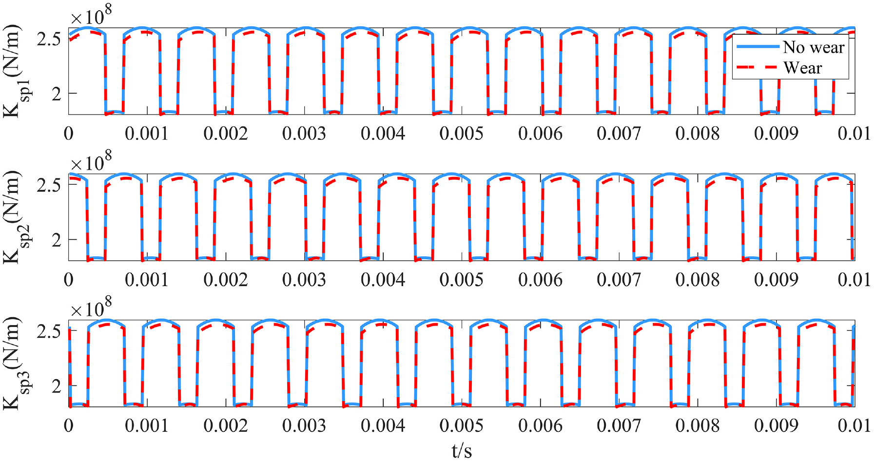
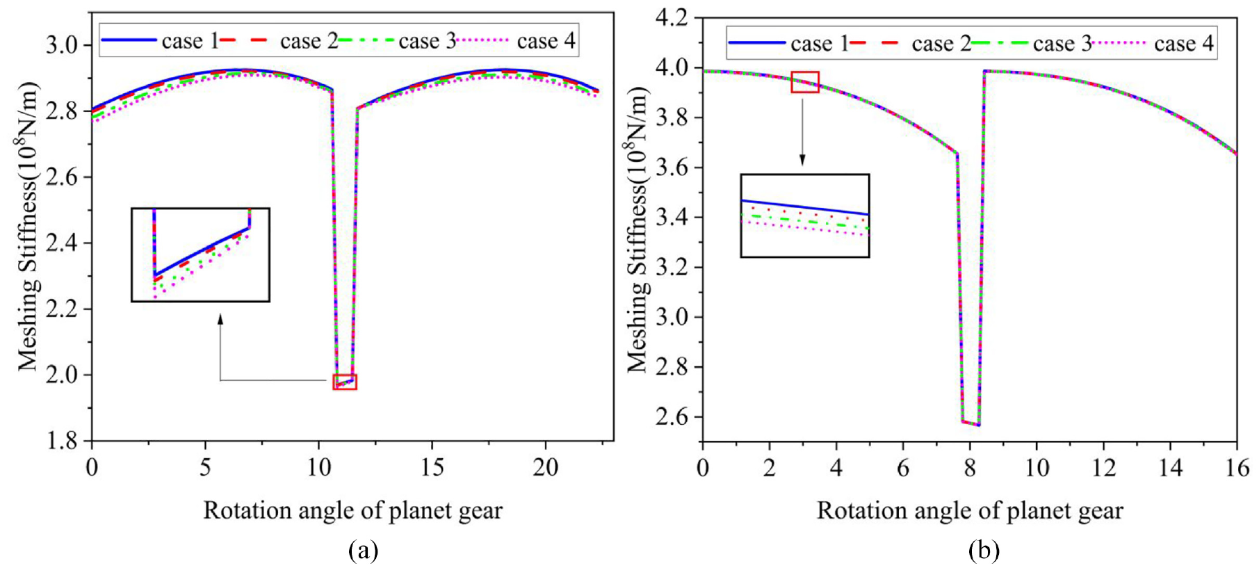
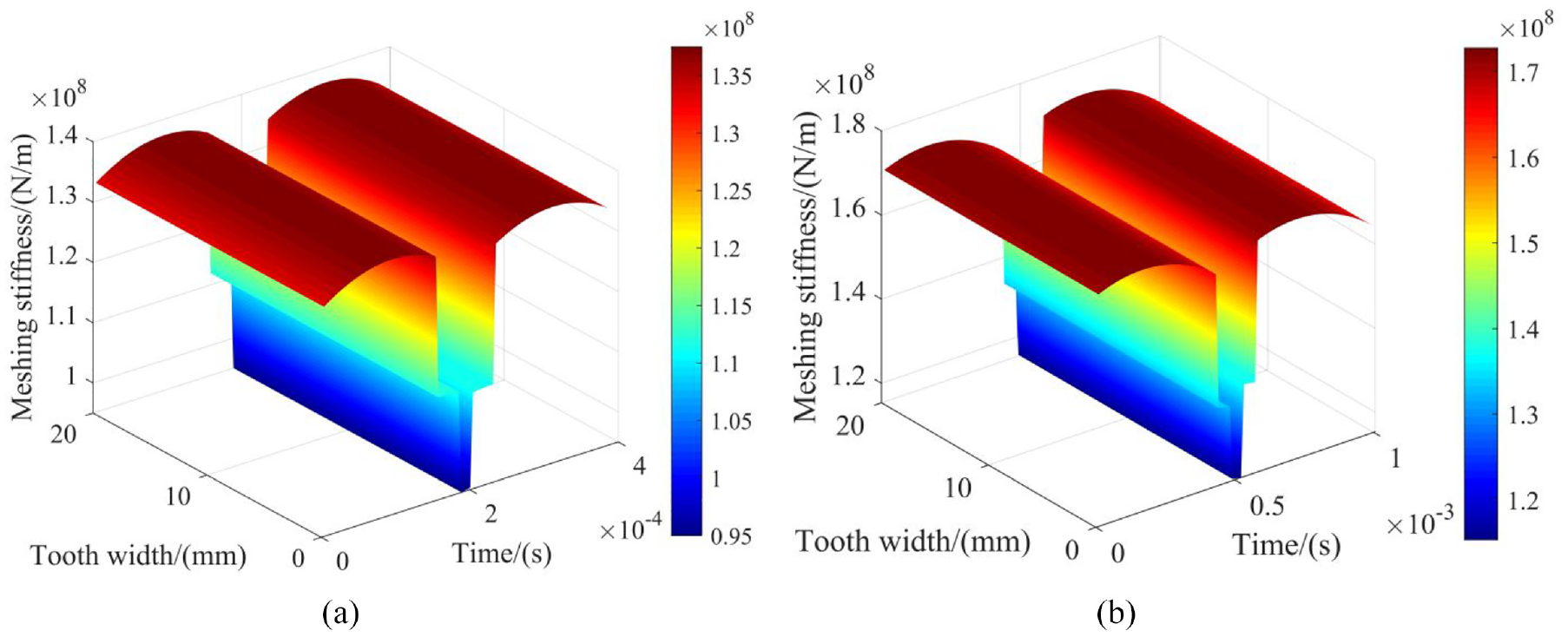
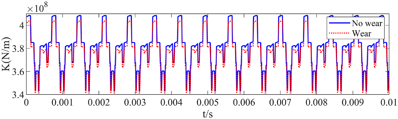
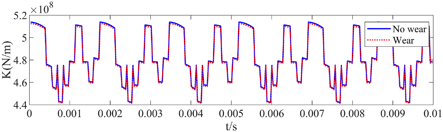
From the Figure 16, It can be found that the TVMS of wear gears is lower than the wearless gears; with the increase of meshing times, the TVMS decreases more obviously. Compared with Figure 16(a) and (b), the TVMS of the first stage is significantly reduced, while the TVMS of the second stage is not significantly changed. The wear becomes more severe as the number of engagements increases. The meshing amount of the second stage is far less than that of the first stage. The parameters of planetary gear train include three planet gears, which together participate in the gear meshing. There is a certain phase difference between the similar contacts; the calculation formula of the TVMS between the similar contact meshing pairs is as follows.


TVMS of sun-planet gears considering wear: (a) first stage and (b) second stage.
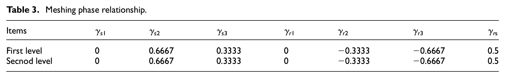
When the planet rotates clockwise, there is a phase difference between the parallel gears. γsi and γsi are the mesh phase differences between planet gears; γrs is the phase difference of sun gear and ring gear; t is the running time of planet gear. T is the meshing period of the gear. When analyzing γsi and γri. Then γrs = 0, the parameters of γsi and γri are shown in Table 3. Amount of meshes of the wear gears is case 4 in Table 1. Figure 17 and Figure 18 are the meshing stiffness of the first-stage planetary gear train and the second-stage planetary gear train with phase difference.
Meshing phase relationship.
The TVMS of sun-planet gears with phase difference in the first stage external engagement.
The TVMS of sun-planet gears with phase difference in the second stage external engagement.
The TVMS of planet-ring gears with wear
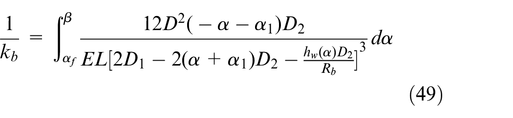
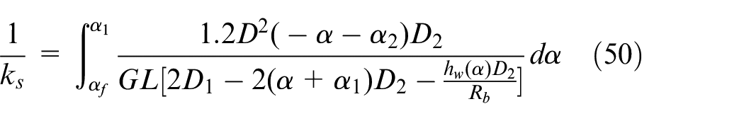
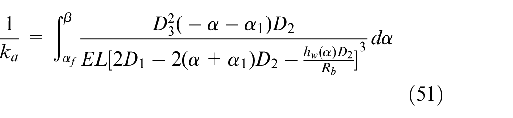
Planet-ring gears belong to the TVMS of internal meshing, The calculation model of TVMS of internal meshing has been established in Section 2.2. The wear of planet-ring gears is analyzed in Section 3.2, so it is only necessary to analyze the geometric parameters. The calculation formula of TVMS with wear condition is deduced according to the geometric parameters after wear, and the TVMS is calculated.
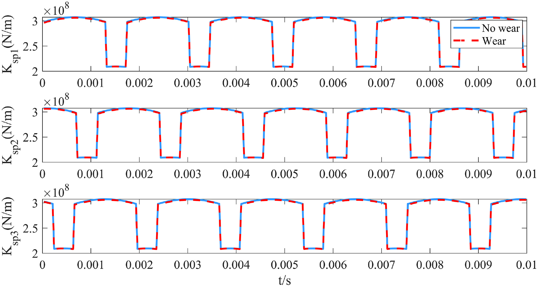
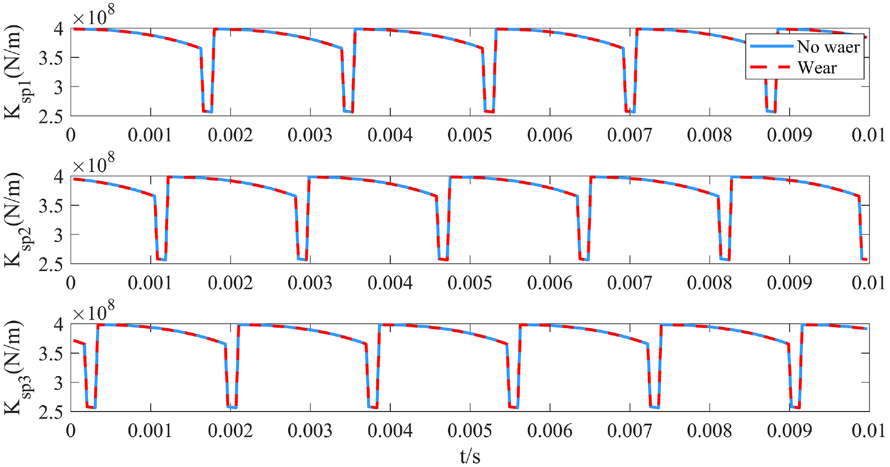
In the Figure 19, wear can reduce gear mesh stiffness, the effect of wear on internal meshing is relatively small. The calculation formula for the flexible stiffness taking into account wear is as follows.
TVMS of planet-ring gears considering wear: (a) first stage and (b) second stage.
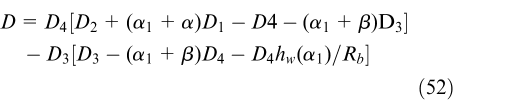
The parameters D1, D2, D3, and D4 have the same meaning as the parameters of the TVMS of the internal engagement of section 2.2, and D can be expressed as.
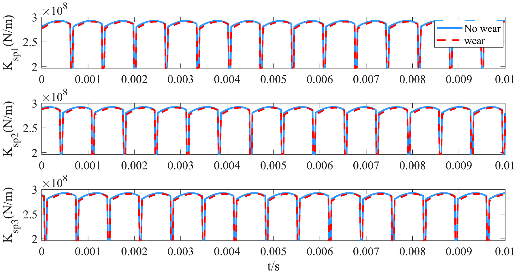
Figures 16 to 21 shows TVMS of wear on the two-stage planetary gear train. Figures 16 and 19 show the effect of wear on the TVMS of a cycle. The wear leads to a decrease in TVMS. On the one hand, wear causes small deformations in the gears, which can change the shape of the tooth profile. On the other hand, the tooth surface reduces the tooth thickness. The results showed that the effect of wear on gear train at all levels was inconsistent. As shown in Figures 16 and 20, the stiffness change of the first stage planetary gear train is the most obvious. However, the TVMS of sun-planet and planet-ring gear is a decline that cannot be evaluated from the diagram; the variation of TVMS in wear state analyzed by the difference calculation method, the calculation results are as follow.
The TVMS of planet-ring gears with phase difference in the first stage external engagement.
The TVMS of planet-ring gears with phase difference in the second stage external engagement.
Figures 22 and 23 show the decrease of TVMS caused by tooth wear, and the decrease of mesh stiffness caused by wear is about 106 N/m. At the same time, TVMS is affected by wear and decreases as working time increases. And from the whole cycle point of view, the decrease of TVMS of sun-planet gear is about 2 × 10⁶ N/m more than the planet-ring gear, which means that the TVMS of sun-planet gears are more serious than the planet-ring gears. However, at each moment, it is necessary to consider γrs; we assume that γrs = 0.5 to analyze the changes in the TVMS caused by gear wear at each moment.
The difference of TVMS under the tooth surface wear of sun-planet gears.
The difference of TVMS under the tooth surface wear of planet-ring gears.
Figure 24 show the comparison of the decrease of the TVMS at each moment. The result shows that due to the causes of phase difference, the influence of wear on the sun-planet gear is not more serious than the planet-ring gear at each moment, so the meshing phase difference is also very important to study the influence of wear.
The variation of TVMS of the sun-planet gears and the planet-ring gears.
A spring oscillator model for TVMS of sun-planet-tooth ring wear
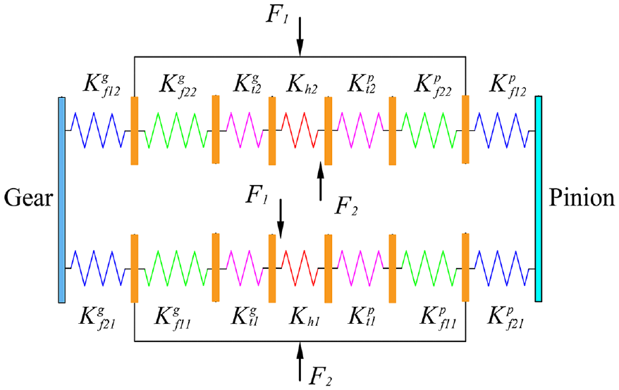
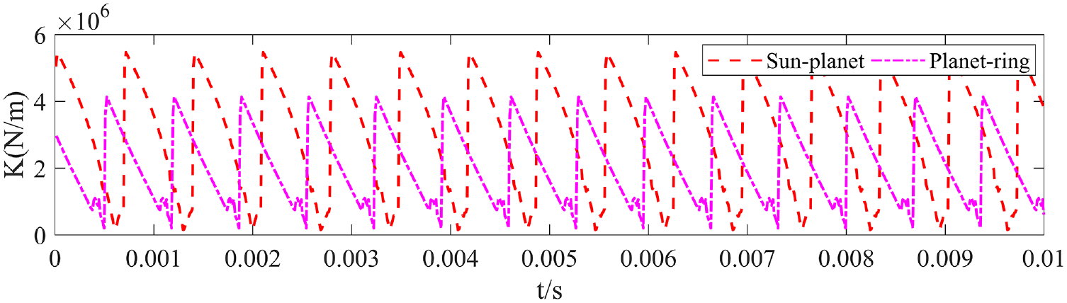
Mesh stiffness and tooth shape error, which are internal excitation sources of gears, can cause changes in dynamic behavior. But the stiffness excitation is the most critical. Due to the simultaneous engagement of sun gear, ring gear, and planet gear, it can be transformed into a spring oscillator structure as shown in Figure 25. And synthetic stiffness model is established, which is regarded as a series relationship. The formula for calculating synthetic stiffness comes from this parallel relationship (Figure 26).
Sun-planet-ring gears spring oscillator model.
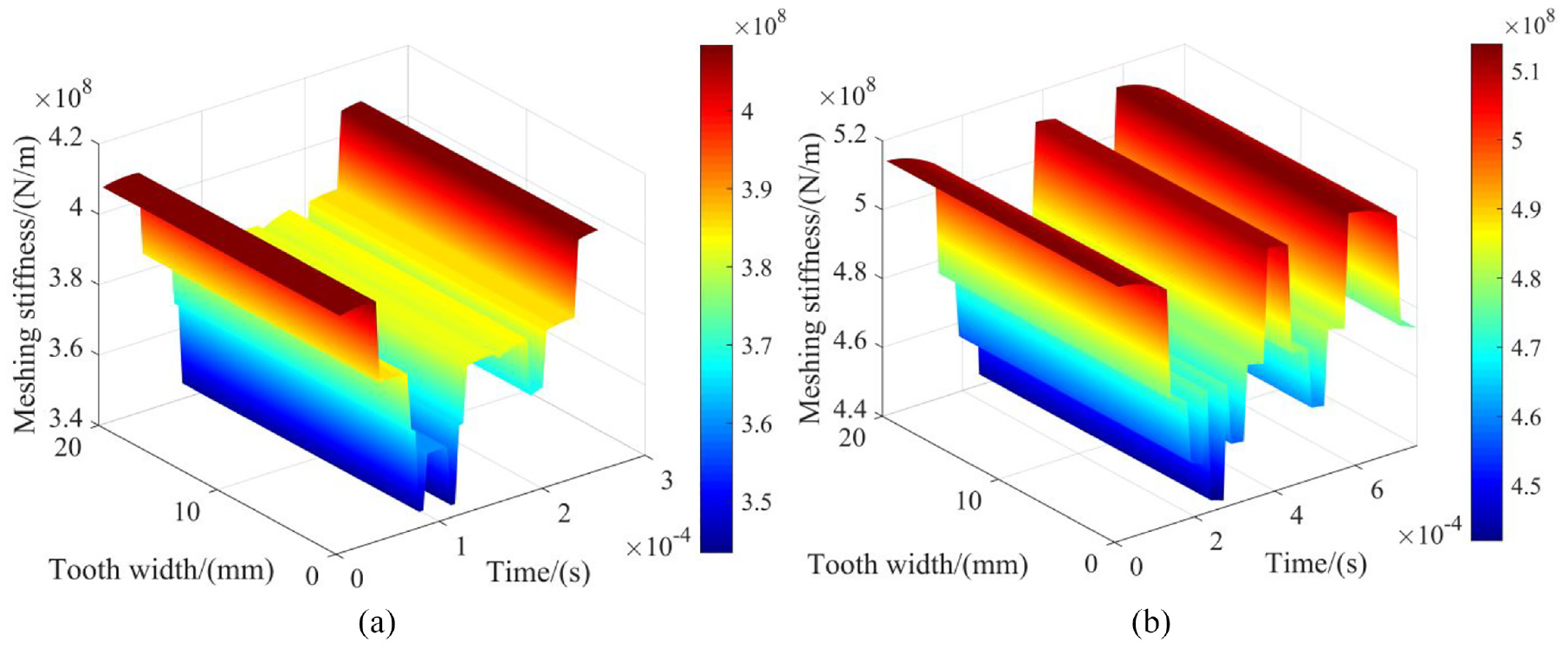
The sun-planet-ring gears synthetic stiffness of planetary gear train: (a) first stage and (b) second stage.
Figure 24 shows the comparison of the decrease of the TVMS at each moment. The result shows that due to the causes of phase difference, the influence of wear on the sun-planet gear is not more severe than the planet-ring gear at each moment, so the meshing phase difference is also significant in studying the influence of wear.
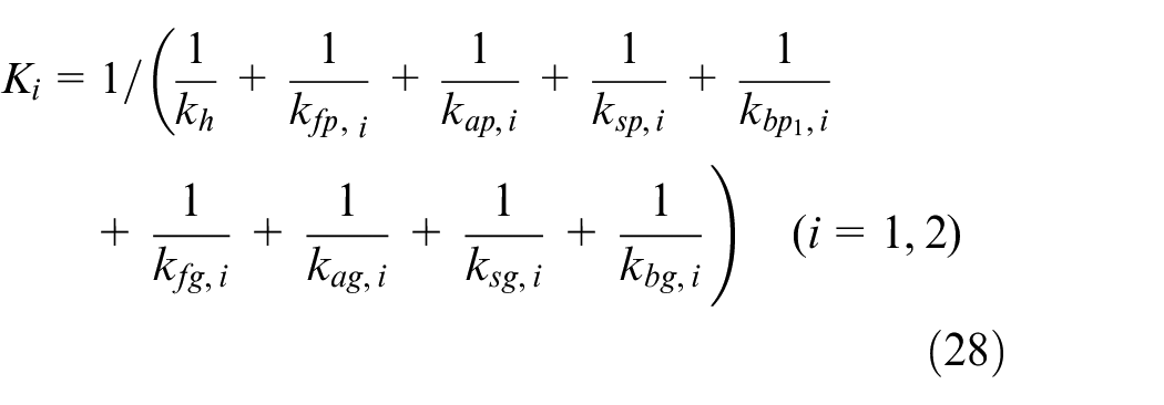
ksi is the TVMS of external mesh; kri is the TVMS of internal mesh; i is the ith pair of planet gear, According to the parameters of Tables 2 and 4, the calculation result of the synthetic stiffness is shown in Figure 26.
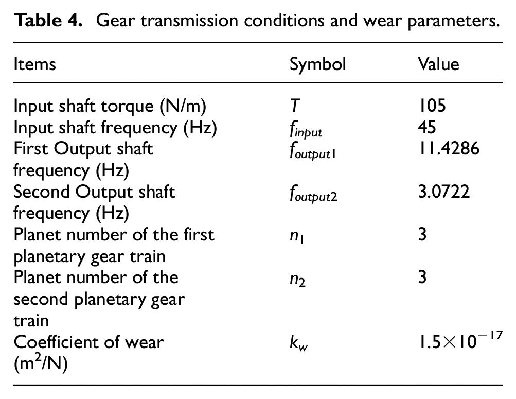
Gear transmission conditions and wear parameters.
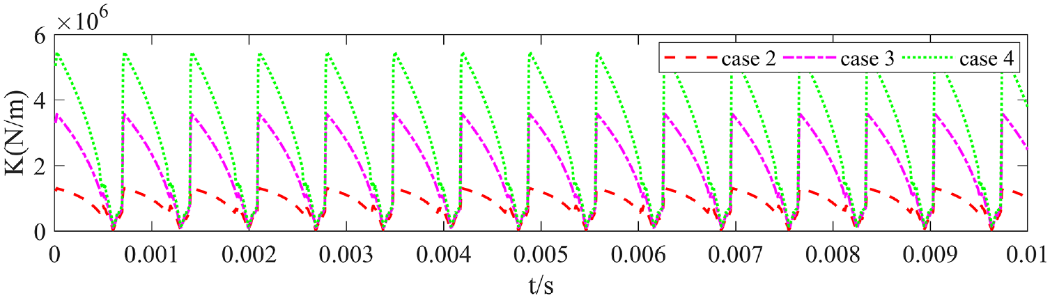
Synthetic stiffness consists of multiple multi-tooth meshing regions in which up to four teeth participate in the meshing simultaneously.
In the planetary reducer, a total of multiple planetary gears participate in meshing at the same time. This paper assumes that there are three planetary gears. When planetary gear train is installed, the phase difference between each group of planetary gear will make the number of engagement teeth inconsistent (Figure 27). In Section 4, the phase difference between planetary wheels is explained, and the meshing stiffness between different phases is calculated. When the influence of wear on meshing stiffness is studied, we cannot ignore the relationship between them.
Planetary gears are considered to be relationship, so the overall composite stiffness of planetary gear train is calculated based on the parallel relationship.
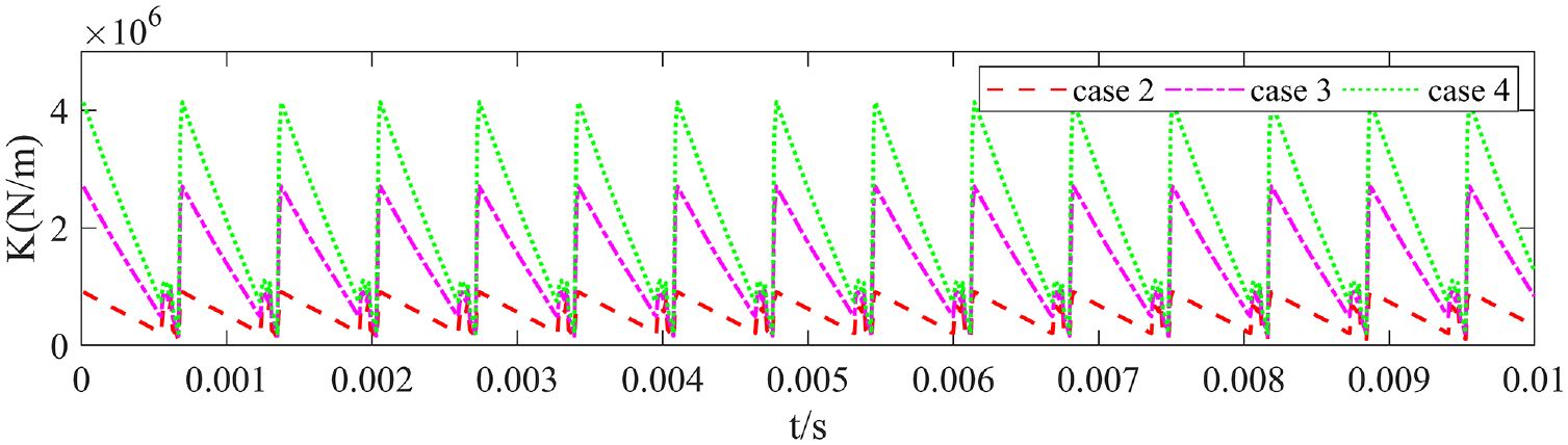
Ksum is the synthetic stiffness of planetary gear train. When considering the influence of wear fault on the synthetic stiffness of planetary gear train, the meshing stiffness of each pair of faulty gear needs to be calculated. The fault meshing stiffness is substituted into the calculation formula of the combined stiffness. The overall stiffness of planetary gear train is shown in Figure 27.
The overall stiffness of planetary gear train: (a) first stage and (b) second stage.
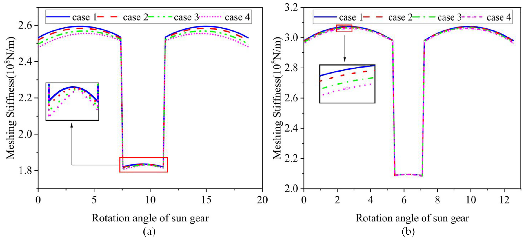
It can be seen from Figures 28 and 29 that the meshing phase difference affects the expression of the composite stiffness of the planetary gear train. Therefore, when studying the influence of wear on the multi-stage planetary gear train, the meshing phase difference cannot be ignored. The meshing phase difference determines the number of teeth involved in meshing at the same time in the planetary gear train. The more teeth involved in meshing at the same time, the more serious the influence of wear.
Influence of wear on the first stage planetary gear train.
Influence of wear on the second stage planetary gear train.
Conclusions
The TVMS model of internal meshing gear is modified by considering the coupling effect between teeth and the contact stiffness under nonlinear load. When two teeth participate in meshing, the meshing stiffness decreases significantly due to the influence of the coupling effect between teeth. At the same time, taking the two-stage planetary reduction as the research object, The TVMS of each gear train with wear conditions are calculated separately, and the TVMS of different meshing methods is also calculated. By comparing and analyzing the meshing stiffness curves with wear state. The results showed that the first stage was more severe than the second stage, and the external meshing stiffness between the same stages is more impact than the internal meshing stiffness. Therefore, the first stage has the greatest effect on the wear dynamic response, and wear of external gear is relatively serious.
Multiple points in the planetary gear train are engaged, and there is a specific phase difference between them. By calculating the TVMS curve with a phase difference, the TVMS of gear wear is quantitatively analyzed. The effect of wear on the multi-stage planetary gear train is complex and changeable, which is affected by the meshing phase difference, transmission ratio, and other external conditions. Meshing phase difference affects the number of teeth engaged at the same time, which will lead to wear on the impact of planetary gear is variable. Therefore, in the design and installation, we should control the phase difference so that the tooth profile error caused by wear on the planetary gear train is less affected.
At the same time, we established the spring oscillator model of the TVMS of the sun-planet-ring gears. The synthetic stiffness under the wear state is calculated and analyzed. The research on the spring oscillator model of the meshing stiffness is of great significance for studying the vibration response caused by stiffness excitation in the two-stage planetary gear train, which is the theoretical basis for faults coupling dynamics of multistage planetary gear train.
Footnotes
Appendix
Declaration of conflicting interests
The author(s) declared the following potential conflicts of interest with respect to the research, authorship, and/or publication of this article: Shuai Mo and Lei Wang contributed equally to this manuscript, Shuai Mo, and Lei Wang are co-first authors of the article. The authors declare that they have no known competing financial interests or personal relationships that could have appeared to influence the work reported in this paper.
Funding
The author(s) disclosed receipt of the following financial support for the research, authorship, and/or publication of this article: This research is financially supported by National Natural Science Foundation of China (No. 52265004), National Key Laboratory of Science and Technology on Helicopter Transmission (No. HTL-0-21G07), Open Fund of State Key Laboratory of Digital Manufacturing Equipment and Technology, Huazhong University of Science and Technology (No. DMETKF2021017), Interdisciplinary Scientific Research Foundation of Guang Xi University(No.2022JCC022), and Entrepreneurship and Innovation Talent Program of Taizhou City, Jiangsu Province.