
Abstract
A novel motor-driven clutch actuator with force-aided lever has been recently developed. A unique spring is used to assist apply of the clutch that can effectively reduce the motor power requirement, and the actuation system can save power consumption during clutch operations with faster response and higher control precision. In this article, a mathematical model of the conceptual clutch actuation system is developed to study the dynamic behavior of the actuator system via computer simulation. The actuator model is further integrated into a dual-clutch transmission and driveline system to demonstrate the effectiveness of the concept in shifting control. The simulation result demonstrates the smooth and fast clutch-to-clutch gear shift and hence validates the feasibility of this new force-aided lever actuation system.
Introduction
The automotive transmission is currently edging toward improving powertrain system efficiency and driving comfort. Smooth gear shifting control is critical for overall drive quality.1–3 Clutch actuation is a key component in the clutch control system, 4 and depending on the transmission type and clutch actuation needs, clutch control can be executed with different actuation mechanisms, particularly for automated manual transmission (AMT),2,5 dual-clutch transmission (DCT),3,6 and various hybrid transmission.7,8 The commonly used systems include electrohydraulic and electromechanical actuation systems,6,9 where the latter has a greater potential for cost-saving and performance improvement.5,10,11 Due to its high mechanical efficiency and control precision, electromechanical systems may become the mainstream in the future.10–12 Compared with electrohydraulic systems, electromechanical systems have faster response, higher energy efficiency, as well as compatibility with intelligent controls.4,12 However, the drawback of these systems lies in the lower force/torque density, so the force/torque capacity is difficult to meet the design requirement and the actuator needs to grow in size, resulting in packaging infeasibility. To address this issue, various force-aided mechanisms have been designed to increase the actuation force while keeping the package compact.
Wheals et al.13,14 proposed a force-aided motor-driven actuator by storing and releasing energy using permanent magnet for AMTs and DCTs. Unfortunately, the mechanism also provides the same aiding force even when the clutch is fully open when zero normal force is required. Therefore, the actuation motor has to generate a force to counter the undesired force from magnet at the open position, which will draw additional energy consumption. Yao et al.4,15–17 designed a wedge-based clutch for automatic transmission, aiming to utilizing the self-reinforcement property from the wedge feature. Kim and Choi10,18 designed a wedge mechanism for an AMT clutch. The intractable issue of the wedge mechanism lies in the self-weakened effect, which occurs when the clutch slipping speed is reversed. This effect can greatly restrict the application of the wedge mechanism.
Preloaded spring, viewed as an energy storage component, is adopted in several force-aided solutions. One mechanism proposed by Jianwu Zhang releases the preloaded spring during clutch engagement assisting an actuation motor.19,20 However, such design is not able to reduce the motor size as the aiding force decreases rapidly with the engagement travel, where bigger actuation force is required. Another design involves a preloaded spring acting on a lever with a moving pivot,21–24 which has been used on a six-speed dry DCT. The experimental results show that the actuation system has a fast response. 25 In general, the controllability of the system is essentially rooted in the monotonicity of the clutch diaphragm, and the actuation system becomes uncontrollable when the diaphragm has a “downward force-travel characteristic.” 26 Lee et al. 27 integrated the spring, lever, wedge, and many other components into an actuation mechanism, and for such complicated system, the reliability, maintainability, and cost limit its practicality.
To date, electromechanical dry-clutch actuation system with large aiding force and good controllability is still of research interest, which includes monotonic or non-monotonic diaphragms. This article is to propose a new force-aided mechanism by adding a rotating preloaded spring to a lever. The spring can rotate along with the lever. With bigger rotational angle, the spring can store and release more energy to assist the clutch apply. In this case, the aiding force becomes larger as the clutch piston travels during the engagement. The aiding force is nonlinear with respect to the rotating angle, and comprehensive modeling and analysis are necessary to study the function and characteristics of the new mechanism.
This article is organized as follows. In section “Design of force-aided lever actuator,” the principle of force-aided lever and the design are presented. In section “System analysis and modeling,” the dynamic model of the actuation system is established. A position-based closed-loop control algorithm is described in section “Controller design.” In section “Results and discussion,” the force-aided feature of new actuation system is studied and the function is validated through simulation. The simulation results demonstrate the performance of the actuator system during clutch engagement. Besides, the force-aided effect, system dynamic characteristics, and controllability are discussed. With the advantages of the fast response, small actuation force, and accurate control, the new actuator system has great potential for practical applications. Finally, the conclusion is drawn in section “Summary.”
Design of force-aided lever actuator
Actuator principle
In a traditional manual or DCT transmission, the clutch is connected to the flywheel and input shaft of transmission. The clutches can be wet or dry.
28
Figure 1 illustrates a normally open clutch. When no force is applied on the piston, the clutch remains disengaged.
28
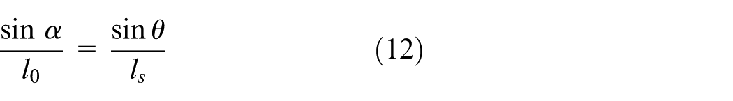
In the assembly in Figure 1, a clutch pack includes pressure plate, friction plate, diaphragm, piston, and actuation lever. The hydraulic system generates an actuation force
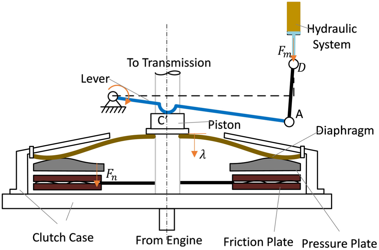
The schematic representation of the dry-clutch assembly with a traditional actuator.
Figure 2 shows an example of the electromechanical actuation system design featured by a moving pivot, which adjusts the force ratio between the two ends of the lever. Besides, one end of the lever is connected to a preload spring, and the lever motion is driven by the preload spring. The spring is compressed and installed along the vertical direction at the end of a lever point B. The other end of the lever point C directly acts against the diaphragm of clutch. In this arrangement, the diaphragm is compressed by the spring force through the lever. A soft leaf spring is attached to the lever on one side and a stiff support D on the other. As soon as the electric motor drives the fulcrum roller O through a power screw, the fulcrum roller in turn pushes the lever along its profile and causes a change in the force arm OB and OC. As a consequence, the piston force

The schematic representation of the dry-clutch assembly with an “existing production actuator.”
In this concept, the driving motor is used to move the pivot, and the associated power consumption would be less than the case when the motor is directly acting on the lever. However, at the same time, it has limited the controllability of the lever rotating dynamics, especially under the negative stiffness of the diaphragm. In what follows, a new electromechanical clutch actuation system with a force-aided feature is proposed.
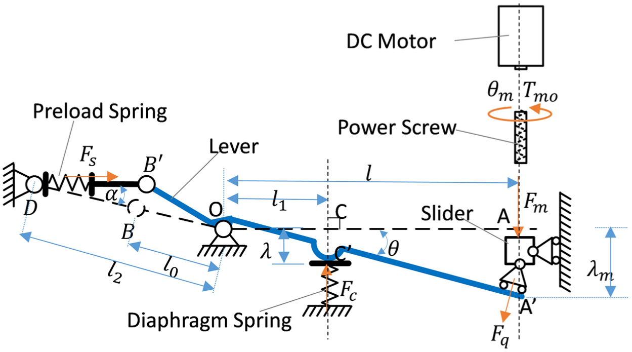
The principle of the force-aided lever for single clutch is described in Figure 3. When the clutch is open, the compressed spring is along the direction of OB. With the force acting on the pivot O in this position, the effective moment generated by the spring force is zero. As soon as the motor force
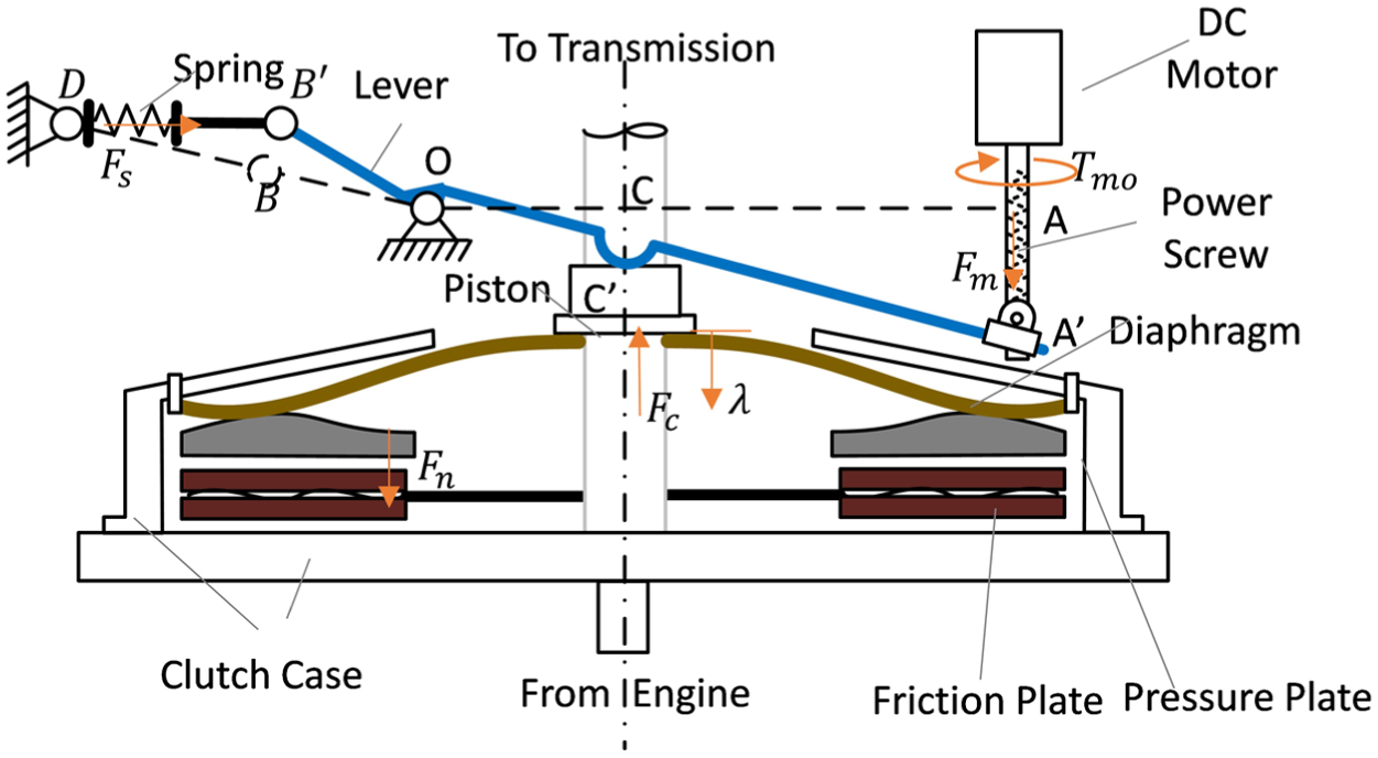
The schematic representation of the dry-clutch assembly with force-aided lever actuation system.
Although both of the electromechanical systems illustrated in Figures 2 and 3 consist of a motor, lever, and spring, their principles differ fundamentally. In the concept illustrated in Figure 2, the force to engage clutch solely comes from the spring, and the motor moves the pivot of lever to change the actual applying force. In force-aided lever actuator in Figure 3, the pivot is fixed, and both motor and spring contribute to the clutch normal force during the clutch apply. The motor provides the torque on the lever directly, so it has a better controllability of the lever rotating dynamics. Consequently, the lever system may have a better stability under the feedback control through the motor.
Table 1 lists the main design properties of the two systems discussed above for comparison. In the existing actuator concept, the pivot of lever is essentially controlled, so that a diaphragm with upward force-travel characteristics can be used, and plus, it needs a high precision in the lever curve manufacturing. However, for the force-aided actuator, the controllability of the system is not sensitive to the lever geometry, but the trade-off here is that it needs a longer lever.
Comparison between “existing production actuator” and “force-aided actuator.”

In summary, the force-aided lever mechanism proposed here has the following advantages. First of all, this electromechanical actuation system appears to be more cost-effective compared to a hydraulic system as it eliminates the need for hydraulic circuits, oil pump, solenoid valves, oil pressure sensors, and other hydraulic accessories. In addition, the force-aided spring assists the motor during clutch engagement, so that a smaller motor can be used with less power consumption. Therefore, a 12-V system is sufficient, which is desired from the economic consideration. Besides, the equivalent aiding force increases with the lever rotation, which means that the spring can provide larger aiding force when needed. This characteristic will be studied in the following section. Finally, the electromechanical system improves control robustness under various transmission operation conditions.
Physical structure
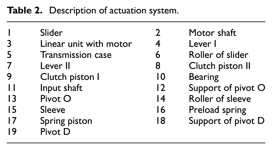
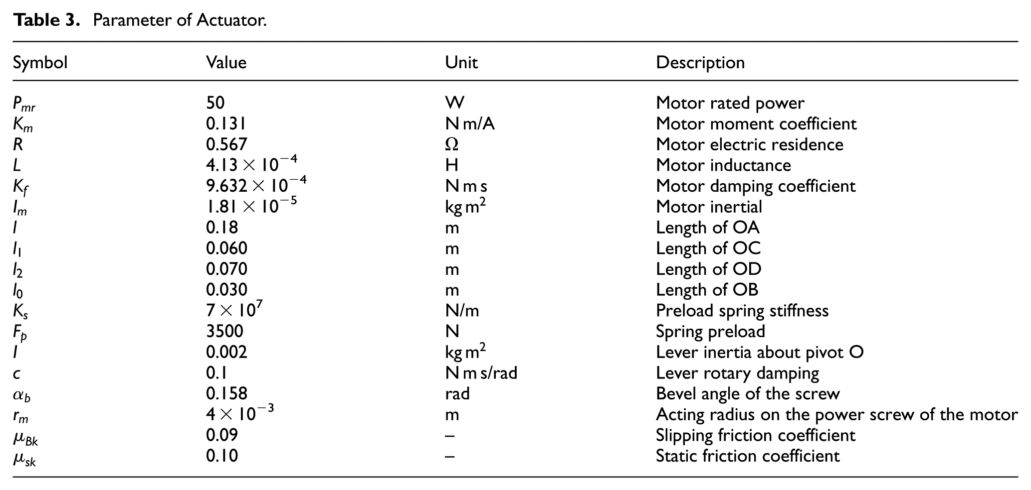
Figure 4 and Table 2 illustrate the layout of the novel clutch actuation system and the name of each part for a dry-DCT transmission. For each clutch, the actuation system includes a preload spring (16), lever (4), linear unit with motor (3), and connectors (2, 6, 12, 14, 15, 17, and 18). The lever can rotate about the pivot (13). Driven by motor (3) through a slider (1), the lever rotates and pushes the clutch piston (9) to apply the clutch. A preload spring (16) is installed on the other end of the lever, which can rotate about the pivot (19). Both of the pivots (13 and 19) are fixed on the transmission case. And a sleeve (15) with a roller is installed between the lever (4) and the force-aid spring (16) to transfer the moment generated by the spring to the lever and then to the clutch piston. A motor is used to move the lever for clutch apply and release. It can be a linear motor or a rotary motor with a power screw. We used the latter option in our prototype for cost considerations. The parameters for the actuation system are listed in Table 3.
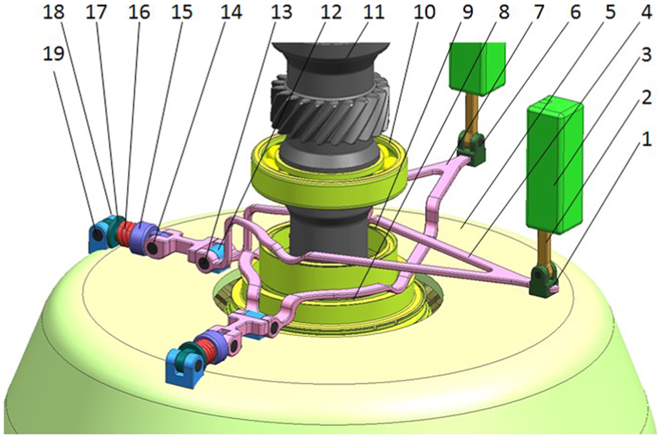
3D model of the clutch actuation system.
Description of actuation system.
Parameter of Actuator.
System analysis and modeling
A numerical model of the force-aid actuation system in a vehicle is developed to study its dynamic characteristics to further validate the performance of the electromechanical actuator. The model is developed in MATLAB/Simulink. It consists of two layers, as shown in Figure 5. The first layer is the actuator model, including the DC motor, power screw, lever mechanism, and accessories; the second layer is the drivetrain model with a DCT transmission including the engine, dual-mass flywheel (DMF), gearbox with two clutches, and vehicle to simulate a vehicle gear shift.

Diagram of dynamic model of DCT with new actuation systems.
Each actuation system model is composed of four main components: motor module, power screw, lever mechanism, and diaphragm, as shown in Figure 6. Most components of this system are treated as rigid body, including the lever, motor, and some connectors. The elastic components such as force-aided spring and diaphragm are treated as pure stiffnesses with the possible inertias are neglected. The dotted line illustrates the position of the lever when the clutch is fully open.
Dynamic analysis of the actuation system.
Motor
The dynamics of the motor consists of electromagnetic and mechanical parts. The resistance of the circuit


in which
Power screw
The ball screw unit consists of a screw, a screw nut, and bearing balls. For convenience of force analysis, the ball screw unit is supposed to be expanded as shown in Figure 7.

Force analysis of the ball screw unit.
The force
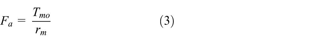
in which,
The force balances of the screw yield

in which,
The force balance of the slider yields

in which,
The equilibrium of the action and reaction forces yields


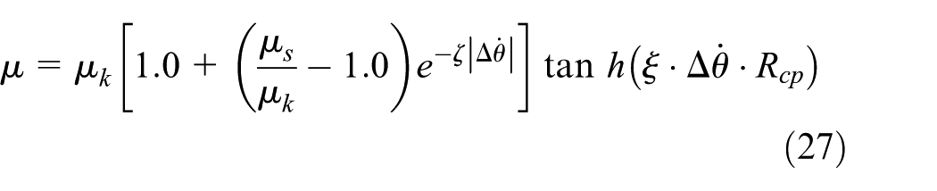
The friction force
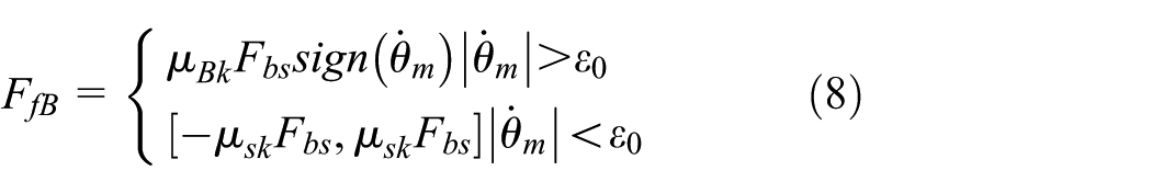
in which,

Coulomb friction model.
Lever
Figure 6 shows the schematic diagram for the system force analysis. The dynamic equation can be written as

in which,

The spring force

where

The motion constraint of lever and the ball screw yields the calculation of

Diaphragm
In this article, the DCT clutches are normally open. Figure 3 shows the diaphragm installation in one clutch pack. During the clutch engagement, the spring exhibits the diaphragm characteristics first in clearance phase before the pressure plate comes in contact with the friction plate, and then, it will behave like a lever spring once they touch.
12
The piston force

in which,

Two typical diaphragm characteristics, “upward force-travel characteristic” diaphragm and “downward force-travel characteristic” diaphragm, are used for the validation of the new clutch actuator, as shown in Figure 9. The piston force

Two typical characteristics of diaphragm for normally open clutch: (a) “Upward force-travel characteristic” diaphragm and (b) “Downward force-travel characteristic” diaphragm.
The powertrain model
The transmission is based on a dry DCT that has six forward speeds and one reverse, with the odd gears on the hollow shaft connected to clutch 1 and even gears on the solid shaft connected to clutch 2. 29 To demonstrate the functionality of the actuator, a typical upshift is investigated without loss of generality. In this case, only a simplified transmission model is used with only necessary components relevant to the shift considered, as shown in Figure 10. Here, the model has been made generic to be able to represent all possible upshift with proper parameters (inertias, ratios, initial conditions, etc.), while the gear selector and its pre-selection procedure are neglected. The drivetrain model further includes engine, DMF, two clutches, gearbox with two-speed gear sets and final drive, half shafts, and a front-wheel-drive (FWD) vehicle body module. The gear shift involves the engagement of the oncoming clutch and the release of the offgoing clutch. Two single-disk dry clutches are housed in a compact assembly which also contains the clutch actuators whose structure has been described.

Simplified two-speed DCT dynamic model.
A 4-degree-of-freedom (DOF) model is built as shown in Figure 10. The first DOF derives from the motion of the lumped inertia
The governing equations of 4-DOF model for the two-speed DCT system are as follows


in which,

The engine output torque

Considering the frontal drag and rolling resistance, the vehicle load torque

in which,

The clutch friction torques

in which,
in which,
Controller design
Actuator controller
For a clutch actuator controller, the input is clutch normal force command, and the output is the motor voltage, which will drive the motor to apply the clutch normal force through the lever mechanism. The diagram is shown in Figure 11.

Actuator controller diagram.
The controller is composed of a force lookup table, a position loop, and a current loop. The force lookup table is based on the diaphragm characteristic (Figure 9), and the motor position command is calculated from the target clutch normal force. Theoretically, if the lookup table is known precisely, clutch normal force can be controlled well if the piston traveling is controlled precisely. Note that the uncertainties of the diaphragm or flat spring usually exist. It needs advance control method to deal with these uncertainties, such as clutch torque estimation or robust control.
Then, the motor position command


in which


Clutch-to-clutch upshift control strategy
Unlike the conventional automatic transmissions, the DCT needs more precise clutch control, since no torque converter is available to dampen possible dynamic impacts during a shift. 31 The clutch torque needs to be controlled precisely for a good vehicle launch and smooth gear shifting. Both the torque and timing are critical. The objective of the shift control is to maintain the possible torque disturbances minimum with the proper clutch control and coordination to achieve good drive quality. 33
The new force-aided lever actuator system needs to execute the typical clutch-to-clutch control strategy with four phases, that is, fill phase, torque phase, inertia phase, and end phase. The desired

Clutch-to-clutch control strategy during upshift.
Results and discussion
The performance validation through simulations for this new system includes three parts. First, the influence of different parameters on force-aided feature will be studied. Second, based on the dynamic model, the actuation performance will be benchmarked with the same actuator without the force-aided spring in terms of clutch engagement and system response. Besides, the stability of the new actuation system will be examined. Finally, the simulation of the actuation system in a complete drivetrain environment including a DCT transmission is used to further demonstrate the actuator capability during a clutch-to-clutch shift. The parameters of actuation system used in simulation are listed in Table 3.
Effect of the influencing factors on aiding force
Suppose the clutch actuator is at equilibrium and the components are static, that is

Substitution of equation (32) into the equations (9) and (10) yields the expression as follows

Equation (33) shows that at equilibrium, the force that compresses the diaphragm is equal to the sum of the actuation force
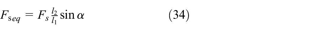
By substituting equations (11)–(13) into the right side of equation (34), the following equation is obtained

The equivalent aiding force
The lever rotational angle

Equivalent aiding force analysis under different parameters: (a) aiding force
Generally speaking, a large spring preload and long
System response for step input
This section will study ultimate responsiveness of the actuation system by following the position step input. Using the control scheme designed in section “Controller design,” the actuation system is validated by the dynamic models with two diaphragms of different characteristics discussed in section “System analysis and modeling.”Figure 14 shows the simulation results for a diaphragm with the “upward force-travel characteristics” (Figure 9(a)). The actuation system generates a normal force on the clutch plate by the lever to a certain position controlled by the motor. The motor angular position reference is given as a step function with an amplitude of 36 rad, which corresponds to a 3000 N normal force, as shown in Figure 14(a). The motor current, motor speed, piston force, and clutch normal force are illustrated in Figure 14(b)–(e). The motor speed increases rapidly at first because the motor current starts at a high value to accelerate the motor. After that, the motor current is kept constant at 8 A, which is the maximum current allowed by the motor, while the motor speed decreases as the piston force

Step response of the force-aided lever actuation system with “upward force-travel characteristic” diaphragm: (a) motor rotational angle
Similar simulation results for a diaphragm with the “downward force-travel characteristics” (Figure 9(b)) are shown in Figure 15. The motor speed is controlled to drop initially followed by an increase from 1.02 to 1.18 s, since the piston force initially increases and then decreases.

Step response of the force-aided lever actuation system with “downward force-travel characteristic” diaphragm: (a) motor rotation angle
Because of the force-aided feature of the actuation system, the clutch engagement can be much faster, as shown in Figure 16. The red line is the command of step input. The response time can be reduced by 24% with the help of the spring (from 205 to 160 ms) for “upward force-travel characteristic” diaphragm and by 19% (from 220 to 180 ms) for “downward force-travel characteristic” diaphragm.

Fast response comparison between actuators with and without spring: (a) fast response with “upward force-travel characteristic” diaphragm and (b) fast response with “downward force-travel characteristic” diaphragm.
Torque-saving characteristic verification
Due to the spring installed, motor torque is reduced during clutch engagement and disengagement. Figures 17 and 18 show the process of clutch engagement and disengagement. The clutch normal force is changed from 0 to 1000 N and to 3000 N finally. With or without the spring, the motor torque is adjusted, so that the normal force is retained following the same profile. Therefore, the force-aided feature can be compared. The spring can reduce about 30% motor torque in both clutch engagement and disengagement. And the force-aided feature is more obvious with the increase in normal force.
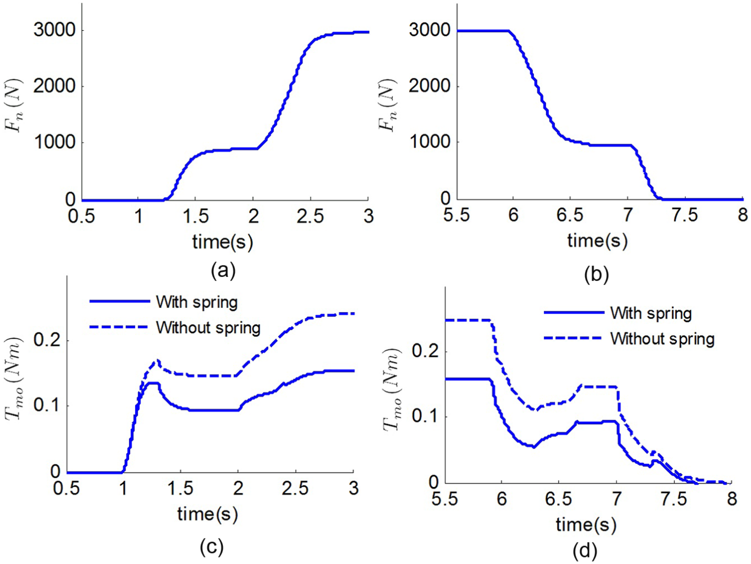
Force-aided feature during clutch engagement and disengagement for “upward force-travel characteristic” diaphragm: (a) clutch normal force during engagement processing, (b) clutch normal force during disengagement processing, (c) motor torque during engagement processing, and (d) motor torque during disengagement processing.

Force-aided feature during clutch engagement and disengagement for “downward force-travel characteristic” diaphragm: (a) clutch normal force during engagement processing, (b) clutch normal force during disengagement processing, (c) motor torque during engagement processing, and (d) motor torque during disengagement processing.
The simulation results in Figures 14–18 show the controllability for both monotonicity and non-monotonicity of the clutch diaphragm since the motor can control the actuation force
Stability validation
This section validates the stability and shows the advantage of the system by comparing to a production actuation system. Both the force-aided lever actuation system and the production actuation system are controlled by the same PID controller with respect to the motor position. Both the “upward force-travel characteristic” and a “downward force-travel characteristic” diaphragms (Figure 9) are used for the two actuation systems for comparison. In addition, the simulation results of the “existing actuator” actuator are provided for comparison. The dynamic model of the “existing actuator” is derived in Appendix.
Figure 19 shows the simulation results with “upward force-travel characteristics” diaphragm (Figure 9(a)). The motor position is controlled by the PID controller, and the equilibrium state of the actuation system is reached at λ = 1.6 mm. To study the system natural robustness of the two actuation systems, a disturbance force is added on the piston (point C in Figure 3)) at 6 s, as shown in Figure 19(a). Both of the two actuation systems with the PID controller can hold the motor position by adjusting motor current, as shown in Figure 19(b) and (c). The piston position of “existing production actuator” actuation system is shifted from 1.6 to 1.7 mm in the presence of the disturbance, as shown in Figure 19(e). The simulation results show that both the new actuator and the existing production actuator actuation system are stable under a diaphragm with “upward force-travel characteristic.” The new actuation system proposed in this article demonstrates higher robustness disturbance than the existing production system.

Stability validation with “upward force-travel characteristic” diaphragm (“force-aided + PID” stands for proposed actuation system with a well-tuned PID controller; “existing actuator + PID” stands for “existing production actuator” system with a well-tuned PID controller): (a) disturbance on piston at point C
Figure 20 shows the simulation results under the same conditions with “downward force-travel characteristics” diaphragm (Figure 9(b)). The equilibrium state of “existing production actuator” seems to be realized and a steady-state normal force at λ = 1.6 mm is obtained (Figure 20(e) and (f)). However, when a small disturbance Fd = 15 N is applied on piston (Figure 20(a)), “existing production actuator” leaves its equilibrium state easily, and the piston travel

Stability validation with “downward force-travel characteristic” diaphragm (“force-aided + PID” stands for proposed actuation system with a well-tuned PID controller; “existing actuator + PID” stands for existing production actuation system with a well-tuned PID controller): (a) disturbance on piston at point C
The simulation results in Figures 19 and 20 show that “force-aided + PID” actuation system has strong stability both with an “upward force-travel characteristic” diaphragm and a “downward force-travel characteristic” diaphragm.
Application to clutch-to-clutch shift
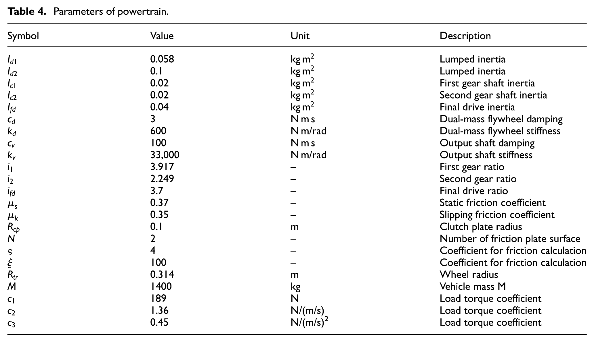
The two actuator models are integrated in the vehicle model. The parameters for the powertrain system used in the simulation are listed in Table 4.
Parameters of powertrain.
The vehicle is simulated with the acceleration under the 25% throttle position. Figure 21 shows the simulation results from the first to second gear. Clutch 1 is the offgoing clutch and clutch 2 is the oncoming clutch. The total shift time here is 0.9 s. The fill phase is finished in 0.1 s. The torque phase lasts 0.2 s, and the inertia phase takes 0.6 s.

Simulation results for upshift process: (a) motor position, (b) motor current, (c) motor speed
In the fill phase, the motor position command (red dashed line in Figure 21(a)) is set to the position where the clutch plates touch each other, and the motor current and speed are controlled to the maximum value allowed in order for the clutch to go through the clearance with a minimum time. At the end of the fill phase, the motor current is changed to a negative value and its speed is reduced to avoid the impact at clutch kiss point. In the torque phase, the normal force on the oncoming clutch increases gradually to take over the normal force on the offgoing clutch. During this time, the engine torque is transmitted from the offgoing clutch to the oncoming clutch. After that, the oncoming clutch normal force is adjusted in the inertial phase, and the speed ratio is changed to the second gear. The down speeding of the engine and the associated inertias during the ratio change can produce a positive driveline torque. The output torque fluctuation can be clearly observed in the inertia phase. As there is no spike in the output torque profile, it indicates no sudden jerk during the shift, and the gear shift process may be deemed acceptable in terms of running smoothness. The motor position follows the command closely, and the clutch normal force profile also shows that it can be controlled well. The results show that this new force-aided lever actuator system is sufficient for clutch-to-clutch gear shift control.
With the force-aided spring, the motor power requirement can be reduced for gear shifting. Figure 22 shows the motor power for the oncoming clutch during the first to second shift with or without the force-aided spring. In both cases, the normal force is controlled to follow the same profile and the vehicle is controlled with the same acceleration profile. From the simulation results, it can be concluded that the spring can reduce about 30% motor power.

Motor power comparison between with and without spring.
Summary
The clutch actuation system is a key enabler for fast and smooth gear shift process for a dry DCT. In this article, a force-aided lever actuation system with a spring driven by an electric motor has been proposed. The design concept and physical structure have been presented. The dynamic model of a DCT equipped with two force-aided lever actuators has been developed. The dynamic simulation results demonstrate the feasibility of the force-aided lever actuator to further validate the actuator design. With the aid of the additional spring, it has been demonstrated that a motor of 50 W is sufficient to actuate the clutch for transmission controls. This is about 30% reduction in motor power required. In addition to the fast response, small actuation force, and accurate control, the new actuator cost is less and has shown great potential for practical applications.
Footnotes
Appendix 1
Figure 23 shows the force analysis of the existing production actuation system. When the roller O is being moved by the motor, the lever is displaced simultaneously with a displacement x of barycenter at horizontal direction, and a rotate angle
in which
where
The power screw is used to transfer the moment motion to the linear motion. The dynamic equation of the power screw is given as follows
The dynamics of the motor are same as equations (1) and (2). The piston force
in which,
Academic Editor: Aditya Sharma
Declaration of conflicting interests
The author(s) declared no potential conflicts of interest with respect to the research, authorship, and/or publication of this article.
Funding
The author(s) disclosed receipt of the following financial support for the research, authorship, and/or publication of this article: This project was supported by the National Natural Science Foundation of China (grant no. 51475284).