A new motor-driven lever-based servo actuator is proposed for automatic manipulation of dry clutches. The dynamic model considering the negative stiffness of the diaphragm spring is built. The characteristics of torque-saving and power-saving are analyzed. Moreover, the stability addressing the negative stiffness is analyzed. The simulation results are verified by the experimental results. The results from quasi-steady experiments show the proposed actuator reduces the motor torque up to 23.9%, the motor power loss up to 38.7%, and the motor output power up to 21.9% compared to the ordinary lever-based actuator. As a whole, the energy consumption during a usual clutch engagement is reduced by 30.1%. In addition, the proposed actuator can track the desired displacement well under the negative stiffness case, and thus overcomes the weakness of the “Luk-like” actuator.
Dry clutches, taking advantages of high efficiency and simple structure, are widely used to engage and disengage rotating components of modern automatic transmissions in vehicles.1 The clutch actuator, applying appropriate normal force on the dry friction plate, plays an important role in enabling the automatic manipulation. The conventional hydraulic or electro-hydraulic actuators2–4 have shortcomings of complexity, oil leakage, and drag losses. Electromechanical actuators are considered as the future mainstream.5–12 However, in order to provide sufficient normal force, the system requires the actuator with high power. Since the actuators in mid-size sedans have the rated output over 100 W, a high amount of electric energy is consumed, which adversely affects the overall fuel efficiency. Power-saving electromechanical actuators for dry clutches are of research interests.
In most dry clutches, the mechanical connection between the friction plate and the actuator is a diaphragm spring whose stiffness is nonlinear with respect to the deformation.13,14 Moreover, the stiffness has a negative phase for the sake of maintaining the spring force and the clutch torque capacity in case that the deformation becomes small due to wear.15–17 But during dynamic process of clutch engagement, the negative stiffness induces instability, which may cause poor tracking performance of the desired normal force. Therefore, the power-saving actuators are required to be controllable under the negative stiffness case, though this requirement has not been noted in previous literatures.
Recently, various lever-based electromechanical actuators were studied for dry clutches. Generally, they are of simpler structure and lower cost than other actuators, such as the wedge mechanism7–12 and moving magnet technology.18 As we know, a lever is a torque amplifier, and a preload spring can release and store energy in internal circulation. Therefore, the combination of a lever and a preload spring may compose a mechanism which is not only torque-saving but also power-saving. In addition, unstable dynamics introduced by the negative stiffness may be suppressed by the motor torque which is adjustable through a feedback control. Typical lever-based solutions are shown in Figure 1.
Typical lever-based actuators for dry clutches: (a) ordinary lever-based actuator,18 (b) conventional lever-based power-saving actuator,19,20 (c) lever-based actuator with a moving pivot (“Luk-like”),21–23 and (d) lever-based servo actuator.
The ordinary lever-based actuator without the preload spring was designed for clutch actuation as well as shift actuation.18 The principle is shown in Figure 1(a), in which represents the force generated by a motor. The motor torque can be small because of the amplification of the lever. Since the motor current is basically proportional to the motor torque, the motor current can be small and the power loss of the motor can be reduced. Besides, because the force produces a moment around the pivot, unstable dynamics of the lever can be suppressed by the adjustable force . However, the limitation is that the required output power of the motor is not reduced. In order to use a motor with less output power, a combination of the lever and the preload spring is designed in Figure 1(b), where the preload spring is arranged vertically to the lever.19,20 Because the preload spring can release its stored energy and provide an aiding moment to the lever, the motor can output less torque but generate the same motion as in Figure 1(a). So, the motor outputs less power. However, the intrinsic drawbacks are as follows: (1) the aiding moment decreases due to the relaxation of the preload spring when the clutch travel increases, which is contrary to the desired servo profile; (2) dynamic analysis shows that the preload force works as a large step input to the actuation system, therefore, collision and vibrations are inevitable. One clever solution is the lever with a moving pivot designed by the Luk company21–23 as shown in Figure 1(c). When the pivot moves, the force of the preload spring produces an aiding moment. And, farer the pivot moves, longer the arm, therefore, larger the aiding moment, and more power-saving. It has been applied to the dry clutches with diaphragm springs which exhibit a “continuously sloping upward” characteristic.14,24 But the actuator cannot manage the diaphragm spring with negative stiffness, which is usually employed in normally closed clutches, as reported by the Luk company.24 The reason is that the force exactly passes through the pivot and cannot provide moment to suppress the unstable dynamics.
The authors propose a new lever-based servo actuator, which can be torque-saving, power-saving, and controllable under the negative stiffness case. As shown in Figure 1(d), the two preload springs are arranged parallel to the lever, so the vertical components of the preload spring forces aid the motor to rotate the lever. The aiding force is zero at the initial position and increases gradually along with the clutch travel. This servo characteristic means that the function of the preload force is like adding a torsional stiffness to the lever instead of applying a large step input like that in Figure 1(c). So, the unsatisfactory dynamic response of the step input can be avoided. In addition, the motor is arranged at one end of the lever which provides feasibility to stabilize the lever by the adjustable motor torque under the negative stiffness case.
In this article, a simulation model is developed for the proposed lever-based servo actuator, which is used to analyze and evaluate its performance. Section “System description” describes the detailed design of the proposed lever-based servo actuator. The simulation model is given in section “Dynamic modeling,” considering the nonlinear stiffness of the diaphragm spring. System analysis is conducted in section “System analysis,” including the characteristics of torque-saving and power-saving, and stability regarding the negative stiffness of the diaphragm spring. In section “Experimental results,” the simulation results are verified by the experimental results; moreover, the results of the proposed actuator are compared with those of the ordinary lever-based actuator and the “Luk-like” actuator, respectively. Finally, the conclusions are drawn in section “Conclusion.”
System description
As depicted in Figure 2, the dry clutch consists of a friction plate, a pressure plate, a diaphragm spring, a thrust bearing, and a case. The rotating motions of the case, diaphragm spring, and the pressure plate are identical to the input engine due to the mechanical connections. The rotating motion of the friction plate is identical to the shaft connected to the transmission. When the clutch is open, the pressure plate does not contact the friction plate, as shown in Figure 2(a). In order to engage the clutch, the thrust bearing pushes the inner circle part of the diaphragm spring; at the same time, the outer circle part pushes the pressure plate to be close to, contact, and finally lock the friction plate, as shown in Figure 2(b).
Lever-based servo actuator for dry clutches: (a) open and (b) engagement.
The proposed actuator is composed of a DC motor, a motion pair converting rotation into translation which includes a ball screw, a slider and a push rod, two preload springs, and a lever. A convex structure on the lever can push the thrust bearing downward. The two preload springs are symmetrically arranged about the output shaft of the driving DC motor. When the clutch is open, the two springs are horizontally positioned, so their preload spring forces are canceled by each other. Therefore, the actuator can be balanced by itself and the DC motor does not need to work. However, during clutch engagement, the DC motor rotates and the ball screw moves downward, thereafter, the vertical components of the two spring forces are downward and generate torque on the lever. This torque actually aids the DC motor. Moreover, the torque is larger at longer engagement travel because the vertical components become larger. This servo characteristic is suitable for the dry clutch because the normal force on the friction plate increases during clutch engagement25 and requires more assistance.
Dynamic modeling
The dynamic model consists of five components, that is, the DC motor, preload springs, ball screw unit, lever, and diaphragm spring as shown in Figure 3. The DC motor and lever are assumed to be rigid bodies; the ball screw unit is regarded as an ideal motion pair without mass; however, friction is considered; the preload springs and diaphragm spring are assumed to be ideal springs without mass. Besides, the effects of varying temperature on the physical properties are not considered here.
Dynamic model of the lever-based servo actuator for dry clutches.
DC motor
The dynamic models are described as below in terms of the electromagnetics and kinetics, respectively26
where V is the voltage applied to the motor, is the angular displacement of the motor, is the motor current, is the electromotive force coefficient, L is the inductance coefficient, R is the electric resistance, is the moment inertia of the motor and ball screw, is the damping coefficient of the motor shaft, is the torque coefficient, and is the load torque which is also called output torque of the motor.
Ball screw unit
The ball screw unit consists of a screw, a slider, and bearing balls. For convenience of force analysis, the ball screw unit as drawn in Figure 4(a) is supposed to be expanded as in Figure 4(b).
Force analysis of the ball screw unit: (a) front view and (b) circumferential view.
The force is generated by the motor and calculated by
in which is the acting radius of the motor torque .
The force balance of the screw yields
in which is the normal force acting on the screw by the balls, is the friction force on the screw, and is the bevel angle of the screw.
The force balance of the slider yields
in which is the normal force acting on the slider by the balls, is the friction force of the slider, and and are the angular displacement of the preload spring and push rod, respectively.
The equilibrium of the action and reaction forces yields
The calculation of the friction force is given by
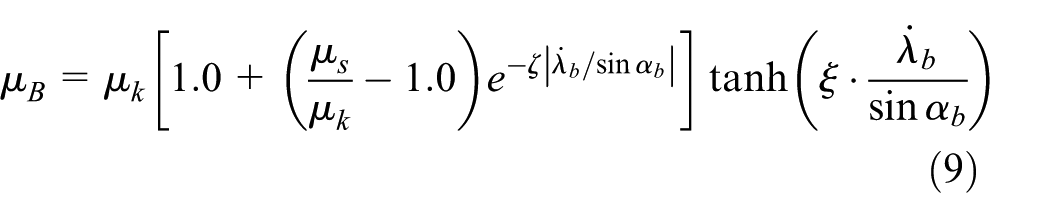
The friction coefficient is calculated using the smoothing function as below27
in which and denote the slipping friction and the static friction coefficient, respectively, and and are two tuning parameters.
From equations (3)–(8), the calculation of the force from the push rod can be derived as
in which
The motion constraint of the ball screw yields the calculation of slider displacement as below
Preload spring
The two preload springs are symmetrically arranged, so the magnitudes of their forces are equal. Each of the spring force is calculated as below
in which is the spring stiffness, is the preload force, and is the length from the pivot D to the central axis of the motor. One notes that the term represents the initial deformation compressed by the preload force; the term represents the new deformation due to the displacement of the end point B of the preload spring. Thus, the summation consists of the total deformation (Figure 5).
The geometry of the spring gives the following relationship
Arrangement of the preload springs.
Lever
As depicted in Figure 6, taking moment balance about the pivot O, the equilibrium equation can be derived as below
in which is the angular displacement of the lever, is the lever length, is the length from the pivot O to the point C which is the contact point between the lever convex and the thrust bearing, is the damping coefficient of the lever, is the moment inertia of the lever about the pivot, and is the force from the diaphragm spring.
Dynamic model of the lever.
One notes that the contact point C is not fixed on the lever due to the convex structure. So, the value of changes along with the angle . Nevertheless, the horizontal component of the displacement does not change and equals to the initial value when the lever is at the horizontal position. Thus, the vertical component (which also represents the displacement of the thrust bearing) of the displacement can be calculated as below
The motion constraints of the angular displacement of the push rod and the angular displacement of the lever are described as below
in which is the length of the push rod.
Diaphragm spring
The characteristic of the diaphragm spring is measured and plotted in Figure 7. The spring force generated at the inner circle of the diaphragm spring is determined by the displacement of the spring which can be represented by the displacement of the thrust bearing. The rate of the force with respect to the displacement is negative in the range of . The generic expression can be written as below
Characteristic of the diaphragm spring: (a) spring force versus displacement and (b) normal force versus displacement .
For the diaphragm spring installed in the clutch as shown in Figure 2, the displacement also corresponds to the normal force acting on the friction plate, as illustrated in Figure 7(b). The normal force should meet the requirement of the clutch operation during engagement or disengagement.
System analysis
In order to validate that the proposed design has the merits of torque-saving and power-saving, this section derives the expression of the load torque, power loss, and output power of the motor, respectively. Thereafter, the stability analysis is conducted, and the evolution of the stability boundary is illustrated in terms of open-loop and closed-loop, respectively.
Torque-saving characteristic
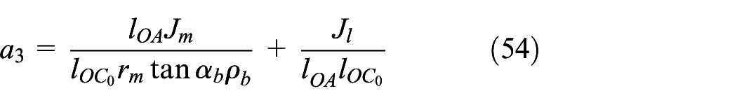
Given the desired normal force on the friction plate, the corresponding desired displacement can be obtained by the mapping defined in Figure 7(b). Thereafter, the corresponding diaphragm spring force can be obtained by the mapping defined in Figure 7(a). The following paragraphs derive the expression of the load torque which can generate the force .
Suppose the clutch actuator is at equilibrium and the components are static, that is
Applying the small angle approximation of the angular displacement of the lever yields
in which the spring force and the angular displacement of the preload spring can be calculated from the displacement of the thrust bearing
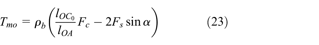
It can be seen from equation (23) that the load torque is the subtraction of two terms. The first term (minuend) comes from the normal force and is associated with the geometry of the lever. The second term (subtrahend) comes from the two preload springs and is associated with the angular displacement of the springs. Once the spring force is positive, the two preload springs can reduce the magnitude of the load torque .
For comparison, the ordinary lever-based actuator as shown in Figure 1(a) is also analyzed. The load torque is expressed as
Subtracting the load torque in equation (23) from the load torque in equation (26) yields the magnitude of the aiding torque to the motor of the proposed lever-based servo actuator
During clutch engagement, longer travel means larger angular displacement of the preload spring. From equation (27), larger () produces more aiding torque . This characteristic satisfies the requirement of the clutch operation.
Power-saving characteristic
The total power consumption of the motor is the summation of the power loss and the output power (i.e. load power) of the motor. This section derives their expressions respectively.
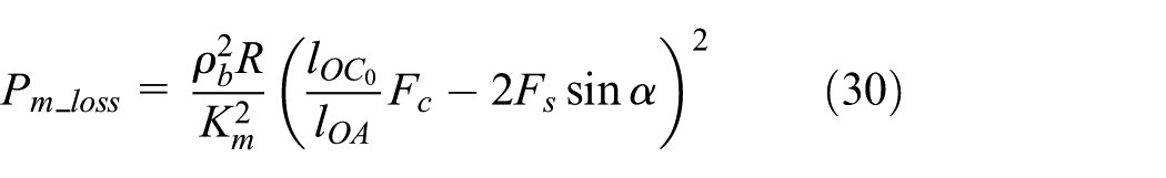
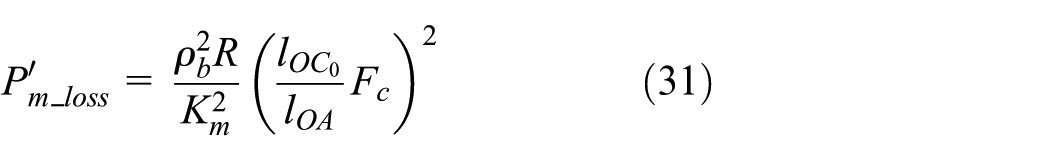
Power loss
The power loss comes from the joule heat and is calculated by
When the clutch actuator moves at a constant slow speed, the motor current can be approximated from equation (2) as below
It can be seen from equation (30) that the kernel of the power loss is the subtraction of two terms. The first term (minuend) comes from the normal force and is associated with the geometry of the lever. The second term (subtrahend) comes from the two preload springs and is associated with the angular displacement of the springs. Obviously, the two preload springs reduce the magnitude of the power loss .
For comparison, similar to the calculation of the aiding torque, the power loss of the ordinary lever-based actuator is calculated by
Subtracting the power loss in equation (30) from the power loss in equation (31) yields the magnitude of the reduced power loss of the proposed lever-based servo actuator
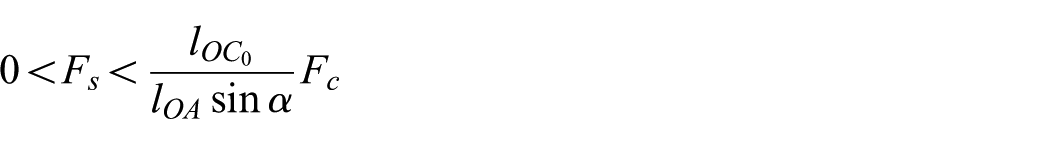
The condition for is
which means the force of the preload spring should be limited in case that the driving motor has to output large current to pull back the lever.
Output power
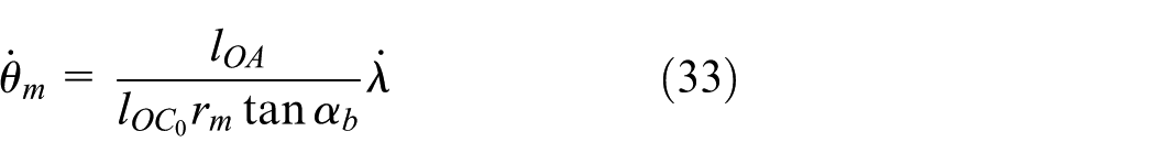
Generally, the output power changes dynamically during the clutch operation. For the convenience of comparison, the derivation assumes the thrust bearing is moving at constant speed . The motor speed can be calculated by substituting equations (21) and (22) into equations (12), (16), and (18)
Therefore, the output power of the driving motor can be calculated as
It can be seen from equation (34) that the output power of the motor is the subtraction of two terms. The first term (minuend) comes from the normal force and is associated with the geometry of the lever, ball screw, and motor. The second term (subtrahend) comes from the two preload springs and is associated with the angular displacement of the springs and also the geometry of the components. Obviously, the two preload springs reduce the magnitude of the output power .
For comparison, similar to the power-loss calculation, the output power of the ordinary lever-based actuator is derived as
Subtracting the output power in equation (34) from the output power in equation (35) yields the magnitude of the reduced output power of the proposed actuator
It can be seen that the reduced output power is associated with the geometry of the lever, ball screw, motor, and preload spring. Particularly, larger angular displacement () of the preload spring reduces more output power .
Stability analysis
The dynamic models show that the nonlinearity is introduced by two factors, that is, the nonlinear characteristic of the diaphragm spring and the trigonometric functions due to the geometry. This section first linearizes the dynamic models in order to derive the transfer function, and then uses the Routh–Hurwitz criterion to conduct stability analysis. Since the open-loop system is theoretically unstable due to the negative stiffness of the diaphragm spring, a closed-loop control is applied to build a stable system. The stability conditions of the open-loop and closed-loop system are analyzed, respectively.
Linearization
The nonlinear characteristic of the diaphragm spring plotted in Figure 7 is locally linearized at an arbitrarily chosen deformation . The mathematical expression can be rewritten as below
in which
In addition to the approximation equations (21) and (22), the angular displacement of the preload spring is also applied with the small angle approximation as below
Because the components of the actuator move during clutch engagement, only kinetic friction is considered in equation (9), that is, .
Defining the incremental variables and , the equation is rewritten as
Taking as the system input and as the system output, the open-loop transfer function is derived as
Stability condition of the open-loop system
The characteristic polynomial of the second-order system described by the transfer function (48) is
According to the Routh–Hurwitz criterion, the necessary and sufficient criterion for a stable second-order system is that all the coefficients are positive or all the coefficients are negative.28 It is apparent that the parameters and are positive because the moments of inertia (, ), the damping coefficient (, ), the dimensions (, , , ), and the coefficient are positive. Nevertheless, a positive depends on the following condition from equation (44)
The above inequality shows the preload should be negative for the purpose of stability when the local stiffness of the diaphragm is negative at . As a result, the force of the preload spring is negative from equation (24). But a negative force increases the load torque from equation (27), instead of reducing the load torque as per the torque-saving objective. This leads to the conclusion that the torque-saving configuration () of the open-loop system cannot be stable under the case of negative stiffness of the diaphragm spring.
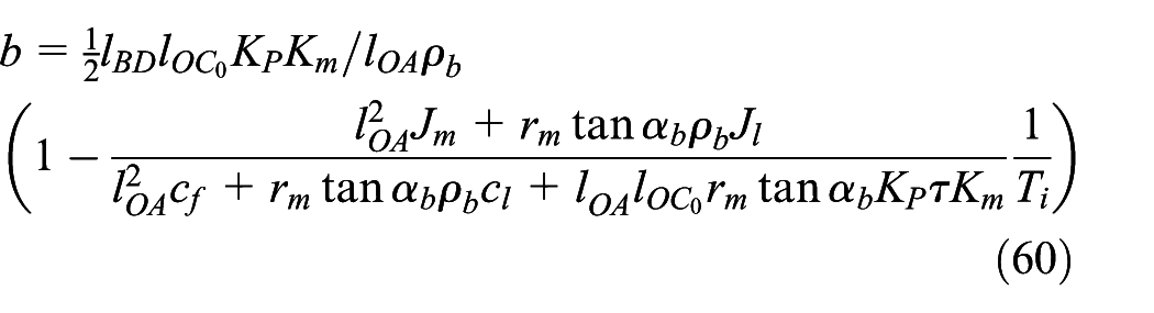
Stability condition of the closed-loop system
In order to stabilize the proposed actuation system, a feedback controller is designed. A generic feedback control scheme is depicted in Figure 8. The motor current is the control input, and the displacement of the thrust bearing is chosen as the feedback signal. Given the desired normal force on the friction plate, the reference input is calculated from the map as shown in Figure 7(b). The desired profile of the normal force refers to Sun and Chen29 and Bai et al.30
Feedback control diagram of the dry clutch actuator.
The feedback control uses the popular proportional–integral–derivative (PID) algorithm with coefficients (, , and ) as below
The closed-loop transfer function is derived as
The characteristic polynomial of the third-order system described by the transfer function equation (52) is
in which
According to the Routh–Hurwitz criterion, the necessary and sufficient criterion for a stable third-order system is that all the coefficients are positive and .28 It is apparent that , , and are positive because the moments of inertias (, ), damping coefficient (, ), the dimensions (, , , ), the coefficient , and armature constant are positive, and the PID coefficients (, , and ) are selected to be positive. Besides, and are positive depending on the following condition
in which
It can be seen from equation (58) that the boundary of the stable region is a straight line featured by a slope k and an intercept b. The slope k calculated by equation (59) is the same as the slope of the boundary line equation (50) of the open-loop system. Similarly, the slope k is only associated with the dimensions. However, the intercept b calculated by equation (60) is associated with the PID parameters and other parameters, such as the moments of inertias, damping coefficients, and armature constant. When , the stable boundary moves upwards; resultantly, there exists stable area for the torque-saving configuration (). Therefore, the PID feedback control expands the stable area.
Summary
Given , , and , the stability condition (equation (50)) of the open-loop system is plotted by the dashed black line in Figure 9(a). It can be seen that the system can never be stable for the negative stiffness case ().
Comparison of the stability conditions: (a) lever-based servo actuator and ordinary lever-based actuator and (b) “Luk-like” actuator.
Given the same dimensions as those used for the open-loop system, together with , , , , , , , and , , and , the stability condition (equation (58)) of the closed-loop system is plotted by the solid blue line in Figure 9(a). It can be seen that the stable region is expanded compared to that of the open-loop system. Under the case that the diaphragm spring stiffness is negative (), the lever-based servo actuator can be stable when the condition (equation (58)) is satisfied. Moreover, it is observed that more negative stiffness, less preload allowed.
The stability condition of the “Luk-like” actuator at the working point is derived in Appendix 1 and plotted in Figure 9(b). The similarity between the “Luk-like” actuator and the open-loop lever-based servo actuator is that the system is unstable when the diaphragm spring stiffness is negative (). As to their differences, the lever-based servo actuator can be stabilized by the closed-loop control, but the “Luk-like” actuator cannot be stabilized due to the constraint of its mechanical principle. In the “Luk-like” actuator, the position of the lever pivot is adjusted by the motor, but the force generated by the motor always passes through the pivot; resultantly, no adjustable moment about the pivot is generated. Wherever the pivot is, the moment balance of the lever is only dependent on the forces of the preload spring and the diaphragm spring, but independent on the motor, as expressed in equation (61). Therefore, the driving motor cannot directly interfere the unstable dynamics introduced by the negative stiffness of the diaphragm spring.
Experimental results
The prototype of the lever-based servo actuator was fabricated and installed in a dual-clutch transmission (DCT), as shown in Figure 10.
3D design and prototype hardware of the lever-based servo actuator for dry clutches: (a) open, (b) engagement, and (c) hardware.
The experimental platform was built as shown in Figure 11. The DC motor is driven by the motor driver, which generates the motor current for the DC motor. The dSPACE controller outputs the current command to the motor driver and runs the PID algorithm if necessary to track the reference displacement of the thrust bearing. The PID algorithm is developed in the computer and downloaded to the dSPACE controller. A force sensor is arranged under the push rod to measure the force of the push rod. The signal from the sensor is amplified before entering into the data acquisition (ETAS611). The angular displacement is measured by the encoder, and the speed is calculated using the displacement data. The motor current is acquired through the motor driver. These signals are collected by ETAS590. All the signals are sent to the computer for data processing.
Experimental platform.
The simulation results of the lever-based servo actuator and the ordinary lever-based actuator are compared with the experimental results, respectively. In addition, the simulation results of the “Luk-like” actuator are provided for comparison. The parameters used in the simulation are listed in Table 1.
Parameters of the proposed lever-based servo actuator.
Acting radius on the ball screw of the motor torque
0. 234
rad
Bevel angle of the screw
0.10
–
Static friction coefficient of the ball screw
0.09
–
Kinetic friction coefficient of the ball screw
20
–
Tuning parameter of the friction smooth function
30
–
Tuning parameter of the friction smooth function
Torque-saving characteristic verification
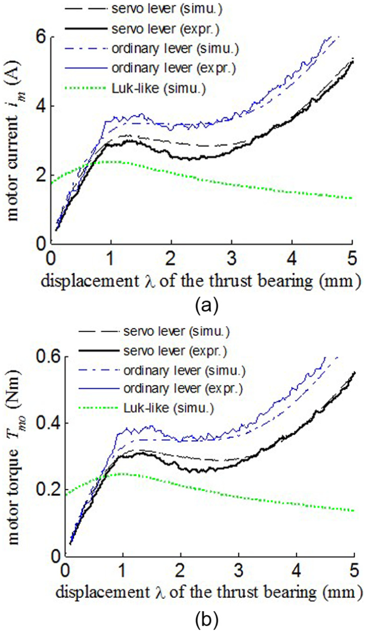
The torque-saving characteristic is verified by quasi-steady experiments because pure steady experiments cannot offer enough effective data due to the effect of the static friction. In the quasi-steady experiment, the driving motor pushes the thrust bearing to move at a constant speed as slow as 1.6 mm/s. The profile of the motor current with respect to the displacement of the thrust bearing is plotted in Figure 12(a). The output torque of the motor is calculated from equation (2) based on the measured data and is plotted in Figure 12(b). The abbreviation of “expr.” represents the results from experiments.
Torque-saving characteristic: (a) motor current versus the displacement of the thrust bearing and (b) motor torque versus the displacement of the thrust bearing.
The simulation results, calculated from equations (23) and (26) represented by the abbreviation “simu.”, match the experimental results well. This is the validation of the modeling of the actuator as well as the derivation of the torque-saving characteristic. The comparison between the results of the lever-based servo actuator and those of the ordinary lever-based actuator shows that the gap between their output torques is small when the displacement is less than 1 mm, and the gap becomes large when the displacement is more than 1 mm. The gap means the reduced torque. The maximum reduced torque is 0.17 Nm, which takes 23.9% of the torque of the ordinary lever-based actuator.
The profile of the motor torque with respect to the displacement reflects the nonlinear characteristic of the diaphragm spring. It can be seen that there are three phases in terms of the slope. In the phase that the displacement is less than 1.4 mm, the slope is positive. In the second phase that the displacement is between 1.4 and 2.4 mm, the slope is negative which exposes the negative stiffness of the diaphragm spring. In the third phase that the displacement is more than 2.4 mm, the slope is positive again.
The output torque profile of the “Luk-like” actuator is rather flat compared to those of the two other actuators. The reason is that the motor of the “Luk-like” actuator is designed to push the pivot by overcoming the resistance of the moving guider. The resistance comes from the friction and a small component of the action force on the pivot. Therefore, the resistance does not change as much as the normal force generated on the friction plate.
Power-saving characteristic verification
The power-saving characteristic is evaluated in terms of the power loss and the output power of the motor, respectively. At first, the generic characteristic, describing how the power loss and output power change with respect to the displacement of the thrust bearing, is illustrated based on the results from the quasi-steady experiments. After that, the dynamic experiments are implemented to complete a usual clutch engagement process.
Quasi-steady experiment
The simulation results of the power loss , which are calculated from equation (28), match the experimental results well, as shown in Figure 13(a). The lever-based servo actuator reduces the power loss up to 3.6 W, which takes 38.7% of the power loss of the ordinary lever-based actuator at displacement . The accumulated energy loss during one travel from the displacement to is 5.8 J for the lever-based servo actuator, whereas 10.1 J for the ordinary lever-based actuator. The former reduces 42.6% of the latter.
Power-saving characteristic under quasi-steady experiment: (a) power loss of the motor versus the displacement of the thrust bearing and (b) output power of the motor versus the displacement of the thrust bearing.
The simulation results of the output power of the motor are calculated from equations (34) and (35). They match the experimental results well, as shown in Figure 13(b). Compared to the ordinary lever-based actuator, the lever-based servo actuator reduces the output power up to 0.8 W, which takes 21.9% of the output power of the ordinary lever-based actuator. The accumulated output energy during one travel is 4.7 J for the lever-based servo actuator, whereas 6.2 J for the ordinary lever-based actuator. The former reduces 24% of the latter.
The simulation results of the “Luk-like” actuator are also provided in Figure 13. The profile of its power loss of the driving motor is rather flat because of the feature of the moving pivot. The accumulated energy loss is 2.2 J which is less than the two other actuators. The output power is bigger than the other two when . The reason is that the motor starts to move from the position near the preload spring, so the lever ratio is rather small; therefore, the driving motor has to move faster in order to obtain the constant velocity at the position of the thrust bearing. The output power decreases to be zero between and due to the negative stiffness of the diaphragm spring. During this period, the force of the diaphragm spring decreases when the displacement of the thrust bearing moves ahead. So, the moment generated by the preload spring becomes larger than the moment generated by the diaphragm spring; resultantly, the pivot does not need to move but the thrust bearing can continue to go ahead. Therefore, the velocity of the driving motor is almost zero, so the output power is almost zero. This phenomenon verifies that the “Luk-like” actuator is uncontrollable under the negative stiffness case. As a whole, the accumulated output energy is 8.3 J which is larger than the two other actuators.
Dynamic experiment
A usual engagement process of the dry clutch consists of three phases, that is, clearance, slipping, and locked. In order to complete the process, the lever-based servo actuator applies the closed-loop control to track the desired displacement of the thrust bearing, which refers to a profile of a clutch in a small-size sedan. So does the ordinary lever-based actuator. The experimental results of the lever-based servo actuator and the ordinary lever-based actuator are compared in Figure 14. Besides, the simulation results of the “Luk-like” actuator are also illustrated for comparison.
Dynamic process during clutch engagement: (a) motor current , (b) motor torque , (c) motor speed , (d) displacement of the thrust bearing, (e) normal force of the clutch, (f) power loss of the motor, (g) output power of the motor, and (h) accumulated energy consumed by the motor.
It can be seen from Figure 14(e) that the normal force generated by the lever-based servo actuator is almost the same as that by the ordinary lever-based actuator. And, the motor speed of the former is almost the same as that of the latter as seen from Figure 14(c); but the motor torque of the former is much less than the latter as seen from Figure 14(b). Therefore, the power loss and the output power of the motor are much less as shown in Figure 14(f) and (g), respectively. At 2.5 s, the power loss of the lever-based servo actuator is 2.0 W, and that of the ordinary lever-based actuator is 3.9 W. The former is 48.7% less than the latter. The output power of the former is 6.7 W, and that of the latter is 9.4 W. The former is 28.7% less than the latter. Besides, the maximum power loss and the output power of the two actuators occur during the clearance phase because the motor speed increases fast in order to finish the phase as soon as possible. The maximum power, which is up to about 60 W, is dependent on the moment of inertia of the motor and speed. Therefore, the power during the clearance phase can be optimized by advanced controls. The accumulated energy consumed by the motor, taking the power loss and the output power into consideration, is calculated in Figure 14(h). At the end of the engagement process, the energy consumed by the lever-based servo actuator is 5.0 J, whereas that by the ordinary lever-based actuator is 7.2 J. Therefore, the lever-based servo actuator reduces 30.1% of the energy consumption.
The simulation results of the “Luk-like” actuator shows that the power loss is less than those of the two other actuators as shown in Figure 14(f). The output power in the clearance phase is much larger than the other two as shown in Figure 14(g) because the motor speed has to be much faster due to the small lever ratio as shown in Figure 14(c). In the slipping phase, the output power is less than the other two when the diaphragm is of negative stiffness. At the end of the slipping phase, the output power is larger than the other two because the motor speed is faster due to the geometry of the moving pivot. In the locked phase, the motor current is much less than the other two because of the merit of the moving pivot. As a whole, the accumulated energy consumption is 4.7 J, which is 6.0% less than that of the lever-based servo actuator. So, the two are comparable in terms of the energy consumption. But the defect of the “Luk-like” actuator is the uncontrollability when the diaphragm spring is of negative stiffness. As seen from Figure 14(d), when the diaphragm spring enters into the negative stiffness phase at 1.47 s (the corresponding displacement is 1.4 mm), the displacement cannot track the desired one. Though, the controller should be good because the tracking performance of the two other actuators is satisfactory, and the tracking performance when the diaphragm spring is of positive stiffness is also satisfactory. As seen from Figure 14(e), the normal force has fluctuation which will deteriorate the smoothness of the DCT powertrain.
Transient response
The experiment of transient dynamics is to show the response of the lever-based servo actuator subjected to disturbance when the diaphragm spring is in the negative stiffness phase. The experiment lets the actuators initially to be stable at (with the corresponding motor current and the preload spring force ). From Figure 7(a), the diaphragm spring at falls into the negative stiffness phase. The disturbance is an impulsive force applied downward to the point B as shown in Figure 3. The transient responses of both the open-loop and closed-loop lever-based servo are compared in Figure 15. Besides, the simulation results of the “Luk-like” actuator are provided for comparison.
Transient dynamic responses of the actuators subjected to disturbance: (a) motor current , (b) motor speed , (c) displacement of the thrust bearing, and (d) normal force of the clutch.
Because the disturbance is unknown for the actuator, the open-loop lever-based servo actuator remains 3.4 A of the motor current. The disturbance force pushes the thrust bearing to move downward. Thereafter, the deformation of the diaphragm spring becomes larger. So, the force of the diaphragm spring decreases due to the negative stiffness. But, the aiding moment generated by the preload spring increases according to equation (27). Resultantly, the lever rotates more according to equation (15) which means the displacement of the thrust bearing increases rapidly from 1.7 to 6.2 mm during the short period from 1.0 to 1.4 s, as shown in Figure 15(c). Accordingly, the normal force on the friction plate has a sudden rise from 30 to 4100 N which will do damage to the clutch engagement.
Although the disturbance is unknown for the actuator, the closed-loop lever-based servo actuator can detect by the deviation of the displacement of the thrust bearing which is the feedback signal. By applying the PID control algorithm described in section “System analysis” (subsection “Stability analysis”), the motor current is tuned to be small at the disturbance point, so the displacement is kept to be unchanged, as shown in Figure 15(a) and (c). That is to say, the stability is maintained by the closed-loop control.
As to the “Luk-like” actuator, the displacement of the thrust bearing increases rapidly from 1.7 to 2.8 mm during the short period from 1 to 1.5 s, as shown in Figure 15(c). The normal force on the friction plate has a sudden rise from 30 to 580 N. The peak value is less than those of the open-loop lever-based servo actuator. The preload spring in the “Luk-like” actuator relaxes and the force decreases, so it can counteract the decreased force of the diaphragm spring to some extent. On the contrary, the force of the aiding torque of the two preload springs in the lever-based servo actuator increases as explained in the previous paragraph.
Conclusion
A motor-driven lever-based servo actuator is proposed for automatic manipulation of dry clutches. The dynamic model considering the negative stiffness of the diaphragm spring of the dry clutch is built. The torque-saving and power-saving characteristics are derived. The stability analysis addressing the negative stiffness is conducted. The simulation results are verified by the experimental results. The performance of the lever-based servo actuator is compared with those of the ordinary lever-based actuator and the “Luk-like” actuator, respectively.
The advantage over the ordinary lever-based actuator is the torque-saving and power-saving characteristics. The results from the quasi-steady experiments show that the proposed actuator reduces the motor torque up to 23.9%, the motor power loss up to 38.7%, and the motor output power up to 21.9%. The results from the dynamic experiment of a usual clutch engagement process show that the proposed actuator reduces the accumulated energy consumption by 30.1%.
The energy consumption of the proposed actuator is comparable to that of the “Luk-like” actuator. In addition, the proposed actuator can track the desired displacement well by utilizing a closed-loop controller under the negative stiffness case; therefore, it overcomes the weakness of the “Luk-like” actuator.
Footnotes
Appendix 1
The “Luk-like” actuator is featured by a lever with a moving pivot, which can tune the lever ratio as shown in Figure 16. One end of the “Luk-like” lever is connected to a preload spring, so the motion of the lever can make use of the energy stored in the preload spring. The function of the driving motor is to move the pivot, so the power is consumed to overcome the moving resistance. However, the motor does not provide torque around the pivot, so it cannot intervene the lever rotating dynamics. Therefore, the motor cannot stabilize the lever system when it is unstable due to negative stiffness of the diaphragm spring.
The dynamic model of the “Luk-like” system is depicted in Figure 17. Because the pivot of the lever can move, the lever dynamics is different from that of the proposed actuator.
The governing equation of the rotating motion of the lever is as below
in which
and is the moment inertia of lever, l is the horizontal distance between the contact points of the preload spring and the diaphragm spring (B and C, respectively), is the displacement of the slider of the ball screw, and is the force of the diaphragm spring which is calculated from equation (19).
The output torque of the motor is calculated by
in which is an coefficient of the ball screw defined in equation (11).
The force of the preload spring is calculated by
in which is the spring stiffness, is the preload force, is the length of a free spring, and is the initial length of the spring. The term constitutes the length of the compressed spring .
The motion constraint of the lever and ball screw yields the calculation of the displacement of the thrust bearing as below
in which is the initial vertical position of the thrust bearing.
The calculation of the output torque of the motor is derived as below
The dynamic equation of the lever is linearized to
Defining the incremental variables , equation (67) is rewritten as
By applying the Routh–Hurwitz criterion, the stability criterion for ``Luk-like'' actuator is derived as below
It can be seen that the stability criterion requires the stiffness to be large enough. Especially, when the displacement is small, the coefficient in equation (69) is a large number, so the stiffness should be very large. In this case, a physical spring may be hard to satisfy the stability criterion.
The parameters used in simulation of the “Luk-like” actuator are listed in Table 2.
Academic Editor: Anand Thite
Declaration of conflicting interests
The author(s) declared no potential conflicts of interest with respect to the research, authorship, and/or publication of this article.
Funding
The author(s) disclosed receipt of the following financial support for the research, authorship, and/or publication of this article: This project was supported by the National Natural Science Foundation of China (grant no. 51475284).
References
1.
WangYLGaoBZChenH.Data-driven design of parity space-based FDI system for AMT vehicles. IEEE/ASME T Mech2015; 20: 405–415.
2.
MontanariMRonchiFRossiCet al. Control and performance evaluation of a clutch servo system with hydraulic actuation. Control Eng Pract2004; 12: 1369–1379.
3.
LucenteGMontanariMRossiC. Modelling of a car driveline for servo-actuated gear-shift control. In: Proceedings of the IEEE international symposium on industrial electronics (ISIE 2005), Dubrovnik, 20–23 June 2005, pp.279–286. New York: IEEE.
4.
OhJ-YParkY-JLeeG-Het al. Modeling and validation of a hydraulic systems for an AMT. Int J Precis Eng Man2012; 13: 701–707.
5.
MingYEQinDTLiuZJ.The control of automatic clutch driven by DC vervo motor. Mach Des Res2003; 19: 35–37.
6.
NanX.Study on the engaging law and control system of the automatic clutch. Harbin, China: Harbin Institute of Technology, 2009.
7.
YaoJChenLYinCet al. Modeling of a wedge clutch in an automatic transmission. SAE paper 2010-01-0186, 2010.
8.
YaoJChenLYinC. Experimental validation of a wedge clutch in automatic transmissions. In: Proceedings of the international conference on advanced vehicle technologies and integration, Changchun, China, 16–19 July 2012. Beijing, China: China Machine Press.
9.
YaoJChenLYinC.Modeling and stability analysis of wedge clutch system. Math Probl Eng2014; 2014: 712472.
10.
YaoJChenLLiuFet al. Experimental study on improvement in the shift quality for an automatic transmission using a motor-driven wedge clutch. Proc IMechE, Part D: J Automobile Engineering2014; 228: 663–673.
11.
KimJChoiSB.Design and modeling of a clutch actuator system with self-energizing mechanism. IEEE/ASME T Mech2011; 16: 953–966.
12.
KimJChoiSB. Self-energizing clutch actuator system: basic concept and design. In: Proceedings of the FISITA 2010 world automotive congress, Budapest, Hungary, 30 May–4 June 2010. Springer.
13.
MyklebustAErikssonL.Modeling, observability, and estimation of thermal effects and aging on transmitted torque in a heavy duty truck with a dry clutch. IEEE/ASME T Mech2015; 20: 61–72.
14.
DeurJMilutinovicMIvanovicVet al. Modeling of a dry dual clutch utilizing a lever-based electromechanical actuator. J Dyn Syst: T ASME2016; 138: 091012.
VascaFIannelliLSenatoreAet al. Modeling torque transmissibility for automotive dry clutch engagement. In: Proceedings of the 2008 American control conference, Seattle, WA, 11–13 June 2008, pp.306–311. New York: IEEE.
WhealsJMcMickingJShepherdSet al. Proven high efficiency actuation and clutch technologies for eAMT™ and eDCT™. SAE paper 2009-01-0513, 2009.
19.
TaguchiYSogaYMinenoAet al. Development of an automated manual transmission system based on robust design. SAE paper 2003-01-0592, 2003.
20.
ZhangJ. Servomechanism for automatic clutch. Google CN1515805A Patent, 2004.
21.
WagnerUBergerREhrlichMet al. Electromotoric actuators for double clutch transmissions. In: Proceedings of the LuK symposium, Schweinfurt, Germany, 2006, pp.137–153. Schaeffler Technologies AG & Co. KG.
22.
FaustIHBünderICDeVincentE.Dual clutch transmission with dry clutch and electro-mechanical actuation. ATZautotechnol2010; 10: 32–37.
KimmigKBührlePHennebergerKet al. Dry double clutch-Success with efficiency and comfort. In: Proceedings of the 2010 9th Schaeffler symposium, Schweinfurt, Germany, 2010, pp.154–163. Schaeffler Technologies AG & Co. KG.
25.
NiCLuTZhangJ.Effect of friction discs wear on dry DCT shifting performance. J Shanghai Jiaotong Univ2009; 43: 1545–1554.
26.
BoltonW.Mechatronics: electronic control systems in mechanical and electrical engineering. Harlow: Pearson Education, 2009.
27.
DuanCSinghR.Influence of harmonically varying normal load on steady-state behavior of a 2dof torsional system with dry friction. J Sound Vib2006; 294: 503–528.
28.
DorfRCBishopRH.Modern control systems. Upper Saddle River, NJ: Prentice Hall, 2011.
29.
SunWChenH. Research on control strategy of shifting progress. In: Proceedings of the SAE international powertrains, fuels and lubricants congress, Shanghai, China, 23–25 June 2008. Warrendale, PA: SAE International.
30.
BaiSMosesRLSchanzTet al. Development of a new clutch-to-clutch shift control technology. SAE paper 2002-01-1252, 2002.