
Abstract
The control scheme of a robotic coax-helicopter was investigated and a control scheme was proposed to simultaneously satisfy not only nominal performance and robust performance but also the complexity, flexibility, and computation of controller design. The complete dynamics was considered including flapping dynamics and inflow velocities. A robotic coax-helicopter dynamic model was reasonable divided into three subsystems to separately design controller based on the analysis of singularity value of the output and each inputs with fully considering the couplings. Every subsystem controller design was based on the comparisons in the performance and design complexity among the previous
Introduction
There has been re-interested in coaxial rotor because of the requirements of high speed and heavy lift.1–3 It has been validated that coaxial rotor consumes less induced power comparing with the traditional single rotor with same blade properties and solidity condition.4,5 Most of researches were focused on the optimum performing coaxial rotor. A comprehensive survey has been concluded in most countries considering inflow structure, rotor spacing, and load sharing from the perspectives of computations and experiments.1,6 In order to seek the highest levels of efficiency, the individual blade geometries were investigated utilizing an optimization method.7,8 However, vertical distance, blade chord, and rotation were also analyzed to search the optimum coaxial rotor performance by a series of researches. 8 Moreover, the dynamic stability characteristics of the coaxial compound helicopter were taken into account and compared with a traditional helicopter in detail. 9 However, only few researches considered the complete model foundation and control design of a robotic coaxial rotor helicopter. 3 In addition, a coaxial helicopter is nonlinear uncertainty and severely coupling plant. These characteristics considerably complicate the control scheme design of coaxial rotor helicopter to achieve high-performance design. 10 Furthermore, not only nominal performance and robust performance but also the complexity, flexibility, and computation of controller design are to be considered seriously, especially in the situation of engineering application. Therefore, following our previous research, 10 we investigated the control problem of robotic coax-helicopter and proposed a new control scheme to simultaneously satisfy the different requirements and constraints of controller design.
As one type of the rotorcraft, the control scheme of the coaxial rotor helicopter is apparently the same as the conventional helicopter. Many control schemes have been brought to a widely successful applications in actual flight test,
11
for example, longitudinal and lateral controller for the attitude hold of the Bell 205 helicopter adopting the
In order to address this problem, the dynamic model is needed to be constructed. The integrative approach was implemented to build the dynamic model in combination with the sum of fundamental components, such as the coaxial rotor, rigid body, horizontal empennage, and vertical fin. It has been showed that the model containing the basic 6-degrees-of-freedom (6-DOF) rigid body and force and torque generation mechanism could satisfy the purposes of control design. In addition, a blade element momentum theory (BEMT) was embraced for the inflow model of a two-rotor system to numerically calculate aerodynamic thrust and torque coefficient. This method has less computation complexity but consistent well with the free-vortex method and experiment data. Furthermore, the flapping dynamics model was regarded as separate DOF using the quasi-static assumption because of its rapid response. Finally, the dynamic model was linearized around hover condition. State and control matrices were derived under an assumption of two main rotors of a conventional helicopter taking use of the analytical formulation.
In this article, the prototype of coaxial rotor helicopter is construed in Figure 1. In particular, most parameters were required to be validated by existed experiments or identified by empirical formulation from open literature. Based on singularity response of the each input and output, the control structure was designed as three parts, the pitch–roll subsystem, the heave–yaw subsystem, and the longitudinal and lateral velocities. In addition, we proposed a new control law using the linear matrix equality to satisfy the flexibility design of performance selection. Finally, each subsystem’s control law was based on the comparisons between the performance and design complexity among the previous full-order

The prototype of robotic coax-helicopter.
Methodology
Model construction
The model is essential for the control scheme. The basic 6-DOF rigid-body model and generation mechanism of aerodynamic force and torque are considered. In addition, the flapping dynamics model was regarded as separate DOF using the quasi-static assumption because of its rapid response. This body-fixed axis has three orthogonal axes. The applied aerodynamic forces and moments of various components were transformed to act along the body-fixed axis. The Newton–Euler equations of motion are commonly applied taking the form of nonlinear differential equations as follows


Here,


where subscripts up, low, H, V, and F indicate upper one, lower one, empennage, fin, and fuselage, respectively.
The relation between the inertia and the body-fixed frame was described by the kinematic equations as follows

The upper and lower rotors’ inflow holds the key ingredient to pursue the force and torque of the rotor in the simulation model. There are complex, inherent, and reciprocal aerodynamic interferences between rotors. However, in predicting the force and moment coefficients, a parsimonious method called the BEMT has been validated to nearly consistent with the free-vortex prediction method, which offers a good approximation of the experimental data. 5 Therefore, this method was adopted to model the inflow with a few adaptations. In addition, it is assumed that the slipstream inflow of upper one interferes the inflow of the lower one, but the lower one does not affect the wake of the upper one. The advancing blade of the upper was on the right side and the lower rotor rotated clock-wise. Therefore, an efficient BEMT is addressed to calculate the coefficients of the rotors as follows 8
Furthermore, it is nature to undertake the blade element theory. In the meanwhile, two-dimensional (2D) and steady airfoil were assumed to calculate the thrust and torque coefficients of the rotors

Blade is assumed to discretize into a series of small radial constant elements. 8 Thrust and torque coefficients of the upper rotor can be numerically integrated as follows

Here,
During the process of control design, flapping dynamics of two rotors is also a fundamental factor. Thus, flapping equation for each rotor is constructed as follows

where

The three terms stand for the coning, the pitching, and the rolling motion, respectively. 5 The first harmonic coefficients relationship between the flapping motion and blade pitching motion is given as follows 11

where
Except for the coaxial system, the dynamic model is also combined with the other fundamental components model, such as the rigid body, horizontal empennage, and vertical fin. Hence, the method of modeling conventional helicopter’s fuselage was expanded to model fuselage of coaxial rotor helicopter. The thrust and torque of the fuselage were supposed that are only affected by downwash of lower rotor. Therefore, an empirical formulation was taken to account the effects of the lower one wake in taking use the isolated fuselage shape. 15 Empirical parameter was applied to calculate force and moment in the dimensions of the rigid body of the constructed coaxial rotor helicopter.
As we all know, the torques and forces of the fin and empennage play key roles in yawing moment and longitudinal equilibrium equation, respectively. However, this effect was evident in the flight, but not well predicted by simulation. 16 Hence, the model of two parts was neglected during modeling.
Linearize
The nonlinear differential equation of the robotic coaxial rotor helicopter is expressed by

The state vector is

And the input vector is

However, it is necessary to trim the nonlinear differential equation at operating condition in order to extract the linear mode. Trim analysis is always complex because coaxial rotor is the underactuated vehicle. In order to establish a square equilibrium equation, the same cyclic pitch inputs were implemented to trim the nonlinear equation of the coaxial helicopter, 17 while the terms of differential collective pitch are not used. In the end, the nonlinear differential equation was solved by the analytical method under small-angle assumption.
As to teetering two-blade configuration for two rotors whose blade are identical in NACA0012 blade sections, radius, planform, twisted rates, and cut-out are shown as follows.
Airfoil parameters
Airfoil NACA0012: the number of blades is 2 (upper rotor and lower rotor), the rotor spacing of 0.1R, chord length of 0.15 m, radius of 1.8 m, deflection amount of 0.1 m, twist rate of −6°, no taper, steer speed of 800 r/min, and teetering rotors.
The distance between the original of the rotor hub and the center of body: 0.3 m, paddle degree: double rotor is 0.106, single rotor is 0.053, the number of Locke is 4, the Mach number is 0.44, the quality factor is 0.7316 and 0.4961. Coaxial quality factor is 0.7770.
Body parameters
The thrust and state variables of upper and lower rotor are outlined in hovering flight. In this case, the transverse and longitudinal periodic variance is the first-order coefficient of the waving coefficient. M = 200 kg,
Trim values in hovering state
Trim values of input are

where the state and control matrices were written in two terms. The elements of the state and control matrices summed the effects of the two rotors, respectively. Thus, the stability and control derivatives are calculated as follows

Control scheme design
The typical control scheme of unmanned helicopter controller
Unmanned helicopter is a kind of system with multiple inputs/outputs and underactuation. However, the helicopter is supposed to accomplish the control state variables, such as attitude, altitude, heading, and velocity. Therefore, arranging the corresponding relation between input and output is the key role in flight control structure design. According to the matching number I/Os, the structures can be divided into the following forms.
The multiloop control structure with cascade single I/O
The characteristic of the kind of flight controller is to divide the system with multiple I/O into several submodules with single I/O and then to design the flight controllers of each submodules. The typical application is Project AVATAR of University of Southern California Institute of Technology and Berkeley’s Maxima. 18 This flight structure is used in widespread open-source flight control, such as Ardu Pilot Mega (APM) and Pixhawk.19,20 Its control structure is shown in Figure 2.

The schematic diagram of the multiloop control system with cascade single I/O.
This kind of structure is most widely adopted at present, and it has been proved by actual tests. It highlights the easy-adjusted controller parameters and has clear physical meanings. However, its control effect, specially the robustness of the controller, is limited because its coupling characteristics between models are ignored, such as the strong coupling between the pitching and rolling channels.
The multiloop control structure with submodules of multiple I/O
The controlled objects are divided into several submodules with multiple I/Os. Then, the multiple-variable flight controller aimed at submodules is designed, and the multiple-variable

The schematic diagram of the multiloop control system with submodules of multiple inputs.
The state variables
This structure highlights the comprehensive consideration of the models, such as the coupling interference between states. Its control accuracy is more effective. But the order of controller is a bit higher, and it is not flexible to adjust the design variables of the controller. Besides, the control accuracy is directly related to the model precision, even a limited-precision model will lead to an unstable circumstance.
The hybrid multiloop control structure adopted both single and multiple I/Os
This method is a combination of the advantages of the above two kinds of structures, which divides the system into submodules of multiple I/O and single I/O. Then, the flight controllers are designed to aim at each submodules. The typical example is the Project R-50 of Carnegie Mellon University, which adopts multiple-variable
The schematic diagram of
In this structure, the inner loop consists of pitching rolling angle submodule, yaw velocity, and vertical velocity submodule, while the outer loop consists of velocity loop, position control loop, and heading control submodule. The inner loop adopts cascade structure in order to select the appropriate feedback value and reference value. This structure remains strong interference coupling, such as pitching and rolling angles. It uses single-variable controller to design the performance figures flexibly. It highlights the full consideration of the dynamic characteristics of the model so that it is convenient to adjust the design parameters of the controller.
Overall, it is necessary to pay attention to the following key points in designing flight control architecture:
The order of submodules don't need to be exorbitanted, and the submodules need to remain the main coupling interference of the model to adjust the performance easily;
The multiple-variable control is suitable to be adopted in pitching and rolling channels because of the strong axisymmetric coupling between them;
The state variable of attitude and velocity can be divided into submodules to design their own controllers, respectively, because the period of lateral motion and the longitudinal motion is longer than that of attitude angle response. In addition, the coupling interference between velocity and attitude angle can be ignored.
The multiple-variable control is suitable to be adopted to control the height and heading because the degree of coupling between the height channels and the pitching rolling channels is quite small. The coupling interference between the height channel and the attitude angle channel is also small.
Singularity response analysis of robotic coaxial rotor helicopter
Multilayer hierarchical control is based on the time scale operating on different time scales and different granularities. 25 Obviously, the control structure is designed based on the model of the manipulation and coupling characteristics. Then, control effect, design complexity of the designer, and easy to implement factor have been considered. Design philosophy based on singularity response.
Singularity response analysis at low frequencies
At low frequencies, the amplitude of the velocity response is significantly higher than the angle. At high frequencies, the gap between the two becomes relatively small. Output singular value responses of the height and angle channel are also at low frequency.
Singularity response analysis under cycle pitch input of the lower rotor
During the vertical cycle pitch input of the lower one, there is a significant coupling between the transverse and longitudinal velocities at the low frequency. The values of pitch and roll are smaller. The singularity response of the height and heading are relatively small at the high and low frequencies, while the vertical cycle pitch input of the upper rotor.
Singularity response between velocity and angle channel
The upper and lower rotor linkage cycle pitch can be adopted. However, the singular value response of pitch and roll angle under upper rotor cycle pitch is higher than the lower rotor cycle pitch. The singular value response value is larger than the use of linkage cycle pitch, and the crossing frequency is higher. Therefore, the pitch and roll angle are controlled by cycle pitch of the upper rotor, while velocity is controlled by cycle pitch of the lower rotor.
Singularity response between the height and the heading channel
There is interference between the height and heading and is affected by the velocity at the same time. In the singular value response curve of the upper rotor, the height channel is relatively obvious at the low frequency. While the heading rate at high frequency is more obvious than velocity channel in the singular value response curve of the lower rotor. The singular value of height channel is relatively obvious for both inputs.
Architectural design
The unmanned coax-helicopter is a multiple I/Os system and there are strong coupling interferences between each of input channels. If the multivariable feedback control architecture is adopted directly, rich debugging experience12–13 of loop shaping is necessary to design the best performance figures. Even a minor adjustment can seriously impact the performance of time domain and frequency domain, and it will also seriously impact the stability of robustness. The architecture of full-order multivariable controller is adopted, which brings better effects to the overshoot and stability margin, but its rise time and decoupling performance still need improvement. Therefore, the architecture analysis and design of the coax-helicopter are quite indispensable.
Based on the analyses and summaries of the typical unmanned helicopter flight control structures, the flight performance figures, the stabilities of robustness, and the engineering implementation requirements are seriously considered. According to the singular value response and the coupling characteristic, a “cascaded double-layer three-submodule” flight control architecture of unmanned coax-helicopter is concluded and shown in Figure 5.

The control architecture schematic diagram of the unmanned coax-helicopter.
In this unmanned coax-helicopter, the inner layer includes the attitude submodule, and the outer layer consists of the velocity submodule and vertical velocity–yaw velocity submodule. Here are the control strategies:
The pitching angle
The vertical velocity w and yaw velocity r are adopted as the feedback quantity of the vertical velocity–yaw velocity submodule. The lateral velocity u and longitudinal velocity v are adopted as the feedback quantity of the velocity submodule.
The state of coupling between pitching and rolling angles is specially outstanding so that they are chosen to constitute a submodule, and the coupling between vertical and yaw velocities also behaves in a similar way. Thus, they are designed into a submodule. The motion period of the lateral and longitudinal rates is much longer than that of the other state variables. Therefore, they are regarded as the same submodule when designing the controllers. The above control architecture retains not only the main characteristics of interference but also the flexibility of controller design with full consideration of the coupling interferences among states of the unmanned coax-helicopter.
According to the coupling characteristics and time characteristics of the analysis results, the specific structure of control system will be split out. Relative gain arrangement (RGA) shows the pairing which is the allocation of control strategy. It is because the period of transverse and longitudinal velocities is greater than the pitch–roll angle. The characteristic curve of the output singular response can be used to illustrate that the attitude of the velocity and the inner can be separated.
The singular value response characteristics curves of a certain input were analyzed for the coupling characteristics. The control system can be put together when the coupling is relatively large and split when the coupling is relatively small. It is illustrated that the heading and height can be put together, as well as the angle and velocity. The key reason is that singular value response are different in the same frequency band.
Therefore, the above can be split into three structures: the upper rotor cycle pitch corresponds to attitude angle (including the angular rate of the two), the lower rotor cycle pitch corresponds to the transverse and longitudinal velocities, and the total distance of the upper and lower rotor corresponds to height and heading rate. Attitude angles are stood for q, θ, p, φ:
State matrix

Control matrix
Output matrix


When the step response is analyzed, the reference instruction and output matrix are expanded to fourth-order matrix. The reference of the angular rate channel is always zero and does not need to be set to 1. The corresponding angular rate is zero from output matrix, and with the reference instruction, the output of the angular rate channel follows the zero. The longitudinal and lateral velocities are given as follows:
State matrix is

Control matrix is

Output matrix is

The state and control matrices of height and heading are given as follows:
State matrix is

Control matrix is

Output matrix is

Comparison Simulation
Previous works
There are a variety of control programs for different application purposes. Scheme for inner
Simulation comparisons
Under the requirements of performance index, robust stability, and easy engineering implementation, the controller of three submodules is designed. The classical
The contrast analysis between the classical loop shaping and the proposed algorithm of attitude submodule is completed. When the same pre-weighting and post-weighting matrices are adopted, the attitude submodule controller of

The controller design and performance simulation of velocity submodule and height-heading submodule using the classic loop forming, based on the LMI loop forming and the proposed algorithm, are compared and analyzed as follows.
Velocity subsystem controller design
According to the state and control matrices derived, the velocity submodule state and control matrices are


The output matrix is
The pre and post-weighted matrices are selected referring to summary of the selection experience. The integral item is used to improve the performance of the controller p, for example, the descent rate of the crossing frequency and the gain at low frequency. The proportional item is used to adjust the lead and lag of the phase.10,21 By adjusting the pre-weighted matrix coefficient, the final pre-weighted matrix is

The post-weighted matrix

The controller for the velocity submodule using the classic


Performance indicators are
Height and heading submodule controller design
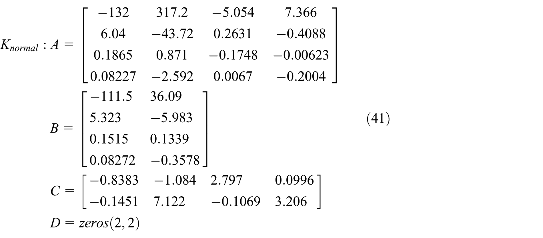
According to the state matrix and control matrix derived, the height and heading state matrix and control matrix are


The calculation shows that rank sum of the matrix
The pre-weighted and post-weighted matrices are selected based on the selection experience. Thus the integral item is adopted to improve the performance of the controller. The proportional item is used to adjust the lead and lag of the phase. By adjusting the pre-weighted matrix coefficient, the final pre-weighted matrix is selected as follows

The post-weighted matrix is

The controller of the height and heading submodule using the classic


Performance indicators are
Simulation results analysis
According to dynamic characteristics and performance indicators, the different control algorithms can be selected for each subsystem’s flexibility. Three controllers are compared in terms of stable margin rise time, stability time, and overshoot step performance indicators.
The performance of the submodule using the low-order controller has been described. Compared with Figures 6 and 7, the controller with the attitude submodule has no overshoot.

Speed subsystem step response characteristics with full order: (a) lateral velocity and (b) longitudinal velocity.

Speed subsystem step response characteristics: (a) lateral velocity and (b) longitudinal velocity.
The rise time is more consistent with the model motion period, and the decoupling performance is also significantly better than full-order design. However, the order is significantly lower than the full-order one. In addition, the controller performance design and adjustment are more flexible and more convenient.
It can be seen from Figure 7 that the three algorithms are consistent with the overshoot and decoupling performance of the unit step response in the closed-loop velocity submodule. The transverse velocity rise time is about 1 s. The longitudinal velocity rise time is about 1.5 s. These two time parameters conform to the movement cycle of the velocity state. The proposed algorithm is faster to reach the stable time than the other two algorithms, but the rise time is shorter. The decoupling performance of classical
The low-order parametric
It can be seen from Figure 8 that the three algorithms are almost identical to the unit step response overshoot, rise time, settling time, and decoupling performance of the closed-loop height-heading submodule. The vertical velocity rise time is about 0.5 s. The rise time of the yaw rate response is about 1 s, which conforms to the motion period of the coaxial double rotor. There is still some coupling interference between the vertical rate and the yaw rate.

Height-heading subsystem step response: (a) vertical rate and (b) yaw rate.
Overshoot of yaw rate step response less than 20%. This is mainly because there is a strong coupling between the two rotor interferences. Adjusting the weight function coefficient is suggested a good way to adjust the performance of closed systems.
Compared with Figure 8, the controller is smaller and the rise time is more consistent with the model’s motion period in Figure 9. The decoupling performance is weaker than the whole-order controller, but the controller order is significantly lower than the full-order controller. The other controllers’ performance design and adjustment are more flexible, and selection of the control algorithm is more convenient.

Height-heading subsystem step response with full order: (a) vertical rate and (b) yaw rate.
Considering the performance index, robust stability, and easy engineering implementation, it is determined that the inner loop adopts the classical loop forming and the outer layer adopts the proposed algorithm. The order of the three subsystem controllers of the cascade three-module flight structure is 8th order, 4th order, and 4th order, respectively. The order of the whole flight controller is 16th order, and the order of the controller adopted full order and classic
Conclusion
The main work is that the control scheme of a robotic coax-helicopter was investigated to simultaneously satisfy not only nominal and robust performance but also the complexity, flexibility, and computation of controller design. The key points of the flight control architecture design are concluded by the analyses to the typical flight control structures of unmanned helicopters. According to the singular value response and the coupling characteristic of the constructed model, a “cascaded double-layer three-submodule” flight control architecture is concluded. The scheme consisted of the submodules of attitude, height-heading, and velocity. The design of the submodules adopts
Footnotes
Handling Editor: Soheil Salahshour
Declaration of conflicting interests
The author(s) declared no potential conflicts of interest with respect to the research, authorship, and/or publication of this article.
Funding
The author(s) disclosed receipt of the following financial support for the research, authorship, and/or publication of this article: This work was supported by Scientific and Technological Development Program of Jilin Province of China (Grant No. 20170101206JC), China Postdoctoral Science Foundation (Grant No. 2014M560232), Foundation of Education Bureau of Jilin Province (Grant No. JJKH20170789KJ), National High-Tech R&D Program of China (863 Program; Grant No. SS2013AA060403), the National Natural Science Foundation of China (Grant No. 51505174), and Research Fund for the Doctoral Program of Higher Education of China (Grant No. 20130061120038).