
Abstract
A complete methodology for an unmanned coaxial rotor helicopter with unstructured uncertainties was proposed to achieve high-accuracy tracking performance from modelling to robust control. An integrative approach was introduced to systematically construct a whole dynamic model. The key parameters were selected carefully after iteratively being checked by empirical coefficients to decrease the budget and risk of programme. Moreover, a new control scheme is proposed to simultaneously incorporate six inputs to control six states based on the investment of singularity value responses and the general rule of relative gain array. Coprime factor uncertainty model is considered to represent a class of unstructured uncertainties, such as unmolded actuator dynamics and unpredicted interferences between two rotors. Furthermore, the
Introduction
Interest in coaxial rotor helicopter has been increasing rapidly in recent years.1–3 The coaxial rotor is a configuration that adopted two coaxially counter-rotating rotors. Compared with the traditional single rotor, coaxial rotor consumes less induced power while exhibits the same blade properties and solidity characteristics under different flight conditions. 4 This configuration has potential to achieve high speed, long range and heavy lift. This type of compact design also would increase efficiency and conserves space. However, a coaxial rotor helicopter is severely nonlinearly dynamic, has a poor model fidelity and strong coupling plant. In addition, there is a reciprocal and unpredicted aerodynamic effect between the upper and lower rotors. These characteristics considerably complicate the modelling and control of coaxial rotor helicopter to achieve high-performance design. Therefore, it will be a challenging work to model and robust control an unmanned coaxial rotor helicopter with uncertainties.
A comprehensive survey on coaxial rotor aerodynamics has been concluded before 1997 in most countries dealing with wake structure, rotor spacing and load sharing between the upper and lower rotors from the perspectives of computations and experiments. 5 A series of research works have analysed the coaxial rotor performance affected by space, blade twist and rotor rotation.4,6 The individual blade geometries were investigated to seek the highest levels of efficiency utilizing an optimization method.2,7 Moreover, aeromechanics optimum design for the coaxial compound helicopter was also taken into account.1,3 In these previous works, however, researchers have mostly focused on performance analysis and optimum rotor. It lacks systematical modelling of the whole coaxial rotor helicopter. Therefore, modelling a coaxial rotor helicopter is needed to further promote.
Robust control law is generally considered an attractive approach to deal with inaccuracies and uncertainties. This method has been implemented to extensive successful actual flight applications, such as a multivariable controller in a vertical and short take-off landing aircraft,
8
an unmanned helicopter design
9
and the Bell 205.
10
In addition, Lin et al.
11
introduced
Therefore, a complete methodology for an unmanned coaxial rotor helicopter with unstructured uncertainties was proposed to achieve high-accuracy tracking performance from modelling to robust control. An integrative approach was introduced to systematically construct a whole dynamic model.
Modelling and trimming
Modelling
The dynamic model with a 6-degree-of-freedom (6-DOF) rigid body has appeared effective for controller design as well as the generation mechanisms of aerodynamic force and torque in the Bell 205 flight test.
10
This method was also considered as a reasonable representation of the key characteristics of a helicopter.17,18 Therefore, this integrative approach is adopted to construct the dynamic rigid body combining with the sum of the forces and torques of fundamental component model. The basic 6-DOF rigid body is fixed at the centre of gravity

Body coordinates in the prototype.
This body-fixed axis has three orthogonal axes, namely, x-axis forwards, y-axis rightwards and z-axis downwards. The applied aerodynamic forces and moments of various components were transformed to act along the body-fixed axis. The Newton–Euler equations are effectively applied in the form of nonlinear differential equations. The forces and moments are contributed by the coaxial rotor, fuselage, vertical fin and horizontal empennage.
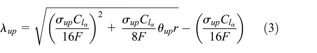
Forces and moments generated by the each component are considered in detail. The coaxial rotor is the key component in constructing a simulation model. Because of the complexity and reciprocal effects between the rotors, calculating the thrusts and torques of the coaxial rotor is a complex and difficult work. However, in predicting the thrust and torque coefficients, blade element momentum theory (BEMT) has been validated to nearly consistent with the free-vortex prediction method 19 which offers a good approximation of the experimental data using full-scale and model-scale coaxial rotors. 20 In addition, it is assumed that the slipstream wake of upper rotor interferes with the inflow of the lower rotor but the lower rotor does not affect the inflow of upper rotor. The advancing blade of the upper rotor was on the right side and the lower rotor rotated clock-wise. Therefore, an efficient BEMT is addressed to calculate thrust and torque coefficients of the rotors in the following way

where
Therefore, the inflow velocity

Blade is assumed to discretize into a series of small radial constant elements.
19


The mathematical principle of the upper rotor was also adopted to calculate thrust and torque coefficients of the lower rotor. In addition, the inflow region of the lower rotor is reasonably divided into two parts. The first one is called the inner part that is fully encountered by the slipstream wake of the upper rotor. The second one is the outer part that is affected freely by the slipstream wake. The boundary of two parts is defined by the ideal radial contraction of the wake of the upper rotor. Consequently, the inflow velocity
For

For

The a factor represents the maximum radial station of the wake of upper rotor. The thrust and power coefficient of the lower rotor can be calculated through the numerical integration as the same as the mathematical principles of upper rotor.
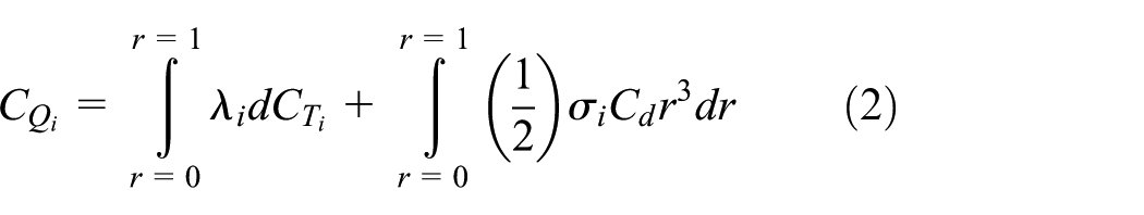
Therefore, the effective blade element theory is applied to calculate the thrust and torque of the upper and lower rotors over the blade span

where T is the thrust, Q stands for torque,
Rotor flapping dynamics is a primary factor in the process of control design. Thus, flapping equation for each rotor is described by
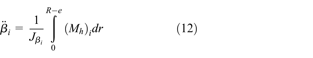
where
The solution of flapping equation was assumed to be periodic. Therefore, first harmonic terms formation of flapping dynamics was sufficiently derived under the quasi-static assumption in the following way

The three terms represent the coning, the pitching and the rolling motion of the tip-path plane, respectively. The first harmonic coefficients relationship between the flapping motion and blade pitching motion is represented as follows

where
Furthermore, the idea of modelling conventional helicopter’s fuselage was expanded to model fuselage of coaxial rotor helicopter. It was supposed that the force and moment of the fuselage only affected by downwash of lower rotor. Therefore, an empirical formulation was adopted to consider the effects of the lower rotor downwash in taking use of the isolated fuselage shape. 21 Thus, the forces of fuselage are calculated as follows

Thus, the forces and moments of the vertical fin and horizontal empennage were considered to be the same as in the literature. 22
Consequently, the forces and moments of each component were summed up in body-axis system to construct the simulation model. The fidelity level of the constructed model is positioned between levels 1 and 2 that enables designing of the controller. This level of fidelity can interpret the cause and effect of model behaviour.
Parameter design and evaluation
Reliable design parameters of the coaxial rotor helicopter are needed to satisfy fundamental aerodynamic constraints. Empirically verified processes are comprehensively and systematically shown to decrease budget and risk in preliminary design stages in Figure 2.

Process of the parameter design.
Gross weight requirement of the coaxial helicopter is 200 kg. Empirical value ranges of the parameter, such as thrust coefficients, tip speeds, solidity and figure of merit (FOM), are selected as the constrained conditions. These parameters reflect the key and fundamental aerodynamic constraints in structure design of the helicopter.
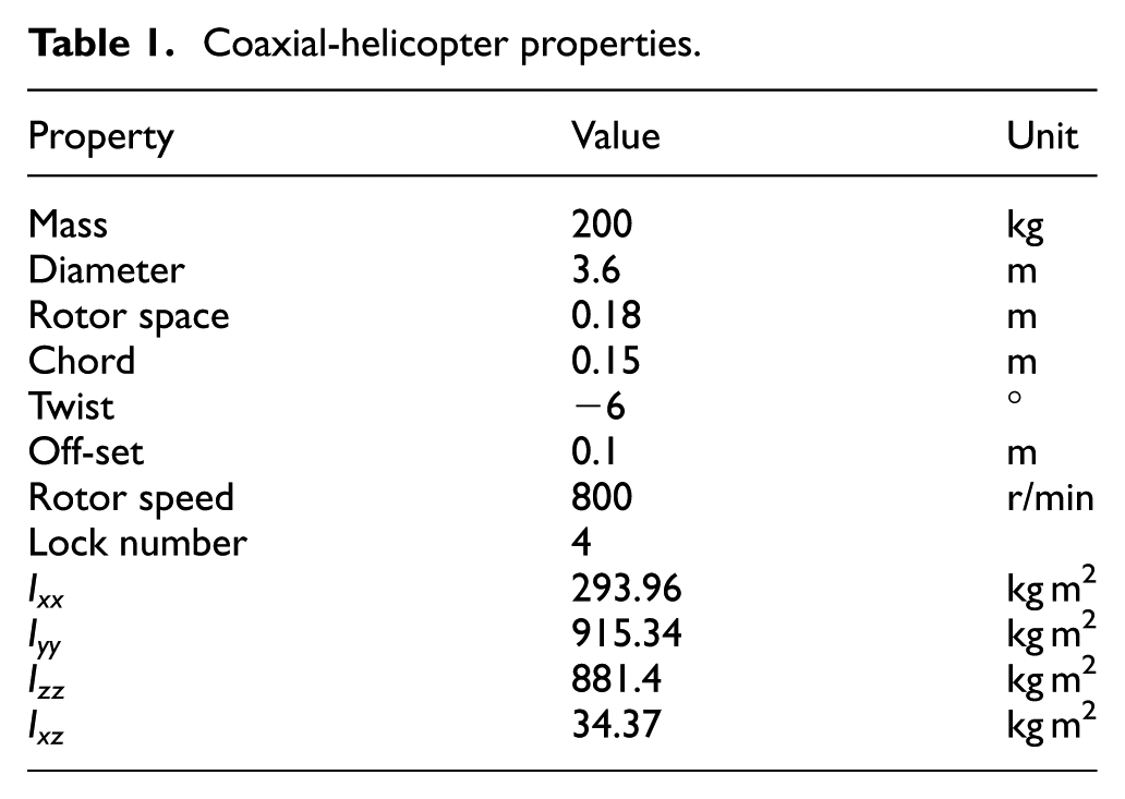
After iteratively being verified by empirical parameter, the reasonable parameters of the prototype are determined, which are shown in Table 1. The structural parameters are shown in Table 2. The configurations of the upper and lower rotors are identical in teetering two-blade including the NACA0012 blade sections, radius, platforms, twisted rates and cut-out.
Coaxial-helicopter properties.
Structural parameters.

In order to show the reasonable and satisfied requirements of the selected parameters, the verified calculation is implemented using the parameters in Tables 1 and 2 as follows:
Thrust coefficient
It is a non-dimensional coefficient to conveniently calculate the rotor thrust. Empirical value range of
Blade solidity
It stands for the ratio of blade area to disc area as follows

Empirical value range of
Disc loading
It is defined as thrust per unit area of disc
Empirical value range of DL is 191.394–574.182 N/m2. 21 Disc area of one of the rotors was considered. The calculated value is 198.8 N/m2 which belongs to the range.
Tip speed
It is used to avoid tip stall and compressibility. The formulation is represented as follows

where
Lock number
It represents the ratio of aerodynamic to centrifugal forces. The heavier the blade, the lower the Lock number 21


Empirical value range of Lock number is 2–10. Carbon fibre was selected as the material of blade. And its density is 1.75 g/cm3. Then, the mass of the single blade is 1.785 kg when the value of thickness of the blade is designed as 0.4 cm. Therefore, the value of Lock number is 4 using equations (19) and (20).
FOM
It is defined as the ratio of induced power to actual power as follows 24


Empirical value range of FOM is 0.75–0.80. 21 Using equation (21), the values of upper and lower rotors are, respectively, 0.7316 and 0.4961. The value of FOM is 0.7770 through equations (22). The other two parameters belong to empirical value range.
Power calculation and engine selection
Power calculation is used to select a suitable engine. The total consumed power of the coaxial rotor is calculate by


Then, the total power of the coaxial rotor is 26.4 kW. After survey of the aircraft engine, Rotax 582 is a perfect choice to satisfy the power requirement.
Gross weight requirement
This requirement is used to guarantee the coaxial rotor helicopter to get off the ground. The trim equation in z-axis is as follows

To calculate equations (7) and (11), thrusts of upper and low rotors are 1141.5 and 881 N, respectively. The drag of fuselage is 60.5 N. Therefore, the gross weight requirement of the coaxial helicopter with 200 kg is satisfied.
Consequently, the e-mathematical calculations show that the parameters are reasonable and sufficient. In addition, the reliable design parameters will effectively decrease the budget and risk of programme (Table 3).
Values of fundamental aerodynamic parameters.

Trimming
Trimming is a significant procedure to equilibrate the nonlinear dynamic equation under the specified flight condition. To establish a square equilibrium equation, the same cyclic pitch inputs for the upper and lower rotors were implemented to trim the nonlinear equation of the coaxial helicopter. 25
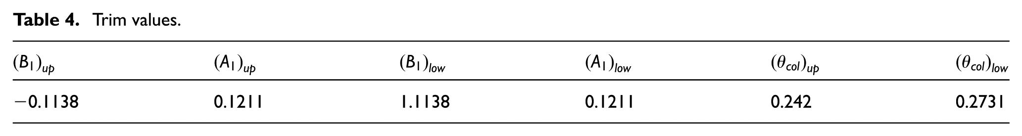
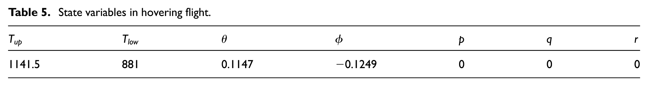
Based on the small angle assumption, the linear equilibrium equations are obtained. Then, these equations are solved using analytical method. The trim values are listed in Table 4. Table 5 outlines the thrust and state variables of the coaxial rotor helicopter in hovering flight.
Trim values.
State variables in hovering flight.
In Table 4, the collective pitch of the lower rotor is slightly higher than the upper rotor. This is because the part of lower rotor’s collective pitch compensates for the larger downwash wake interference from the upper rotor. It is found that lateral cyclic trim values are larger than longitudinal cyclic pitch values to balance the equilibrium equation in the constructed model.
Another interesting consequence is that the upper rotor shared 56.4% of the total thrust under torque-balanced condition (Table 5). This is the reason that some of induced power of lower rotor is lost. In addition, the thrusts ratio exhibits a good agreement with other unrestricted experimental results. 20 Consequently, the trim and state values show that the constructed model is an effective representation of the main characteristics of the coaxial rotor in hovering condition.
Dynamic stability and singularity
Dynamic stability characteristics of a coaxial rotor helicopter absolutely restrict the goal of control design. Small perturbation theory was adopted to calculate the stable and aerodynamic derivatives of the coaxial rotor helicopter at hovering condition. Furthermore, the superposition of individual effects of the upper and lower rotors is supposed to depict changes in the dynamic system of the constructed model. Effects of the coaxial rotors are linearly added by assuming the helicopter with two main rotors. Therefore, the linear model is derived as follows

where the state and control matrices were written in terms of

The state vector is

The natural modes of motion are indicated by the eigenvalues of the state matrix as shown in Table 6. Pitch subsidence, roll subsidence and heave subsidence modes of the constructed model are stable. However, the model is unstable in the yaw mode, which most likely lacks a tail rotor. Two complex conjugate pairs on the right half plane exhibit unstable oscillations of longitudinal and lateral dynamics. The first conjugate pair attributes to the coupling of pitch and longitudinal velocity by speed stability. The second is caused by the coupling of roll and lateral velocity. These two results are also similar to the phenomenon in a conventional helicopter. The distribution trend of natural modes of the constructed model also coincides well with the results of other research. 1 Consequently, the constructed model is unstable without an automatic augmentation system.
Eigenvalues of the model.

After calculating the state and control matrices, it is necessary to consider control scheme as diagonally dominant as possible with input–output pairing. Time-domain method is not efficient to analyse the relationships between inputs and outputs because of divergences of the unstable model response. Therefore, singularity value response was implemented to contribute to the controller structure design in frequency domain.
Figure 3 indicates that considerable couplings are observed between longitudinal velocity and mixed-rate pitch. The differences of responses that longitudinal velocity and mixed-rate pitch with respect to the longitudinal cyclic pitch of upper and lower rotor are minimal. Moreover, the longitudinal cyclic

The longitudinal cyclic to states: (a) upper rotor and (b) lower rotor.
It shows that there are considerable couplings among the controlled variables with respect to lateral cyclic input, as shown in Figure 4. The difference between lateral velocity and mixed-rate roll is small. The longitudinal velocity u and lateral velocity v are clearly affected by the longitudinal

The lateral cyclic to states: (a) upper rotor and (b) lower rotor.
As shown in Figures 3 and 4, inherent cross couplings are observed between longitudinal and lateral motions. These findings indicate that the constructed dynamic model has an ability to depict the basic axis symmetry characteristic of a coaxial rotor helicopter.
Serious couplings between heave and yaw motions are observed (Figure 5). The couplings between longitudinal-lateral dynamic and heave-direction dynamic also exist. However, the collective pitches of two rotors are more effective on vertical velocity w and yaw rate r than the other controlled variables. Moreover, the collective pitch of the two rotors significantly affects heave motion than yaw motion, as shown in Figure 5. Therefore, one of the two collective pitch can control vertical velocity. The remaining input could be used to control yaw rate.
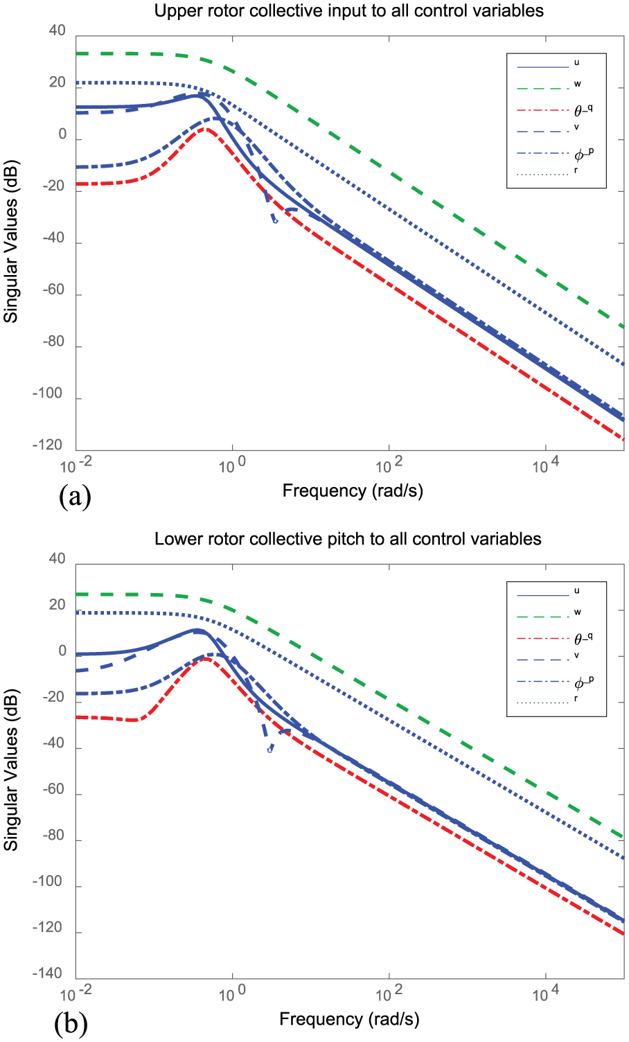
Collective pitch to states: (a) upper rotor collective and (b) lower rotor collective.
In summary, the singularity value response simulations show that the constructed model experiences complicated couplings among channels, as shown in Figures 3–5. The relationship between input and output is unclear. Some situations are even confusing. In order to contribute to make the control scheme as diagonally dominant as possible, it is needed to investigate the characteristics of the constructed model further.
Robust control design
Control theory

The nominal plant G is shown in state-space form

The shaped plant

Coprime factor uncertainty model is adopted to consider a class of unstructured uncertainties. Then, the perturbation model of normalized factorization formula of plant is described as follows

where

where

To simplify plan G, assumed that

where
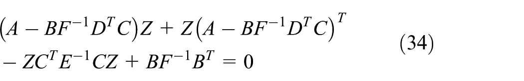
The performance index is given by minimizing the infinity norm of the transfer function matrix between exogenous signal vectors and objective signal vectors

For a given

Consequently, the controller law for a coaxial rotor helicopter is
Control structure design
Some researchers have been investigating control structure of a helicopter. Heave–yaw and roll–pitch controllers were designed for a coaxial micro helicopter in the literature. 27 Cai et al. 28 proposed a hierarchically divided three-layer flight control structure law for a small-scale unmanned helicopter. Inner- and outer-loop architectures were introduced into the design and flight testing of the controller of a robotic helicopter. 29 However, the coaxial rotor helicopter has additional input DOFs to control structure design. It is normally required to adopt a different control strategy and scheme. Therefore, it is implemented to select the reasonable input–output pairings with additional inputs. Relative gain array (RGA) is adopted to provide a suggestive rule to arrange dominant elements as diagonal as possible following the analysis of the mentioned singularity value responses. Its formulation is as follows

where the transfer function form of the plant is represented as follows

where
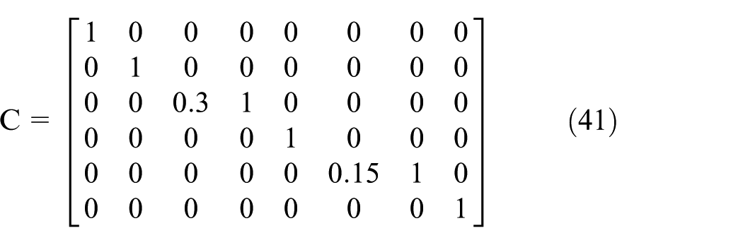
A mixed-rate technique is adopted.
Taking equations (39) and (40), the steady-state RGA matrix of the constructed model is rearranged using the rule of RGA

Based on the singularity value response simulation results in section ‘Dynamic stability and singularity’ and rearranged RGA matrix in equation (42), the control architecture of the coaxial rotor helicopter is constructed, as shown in Figure 6.

Block diagram of the controller.
The rearranged controlled variables order is
Control synthesis
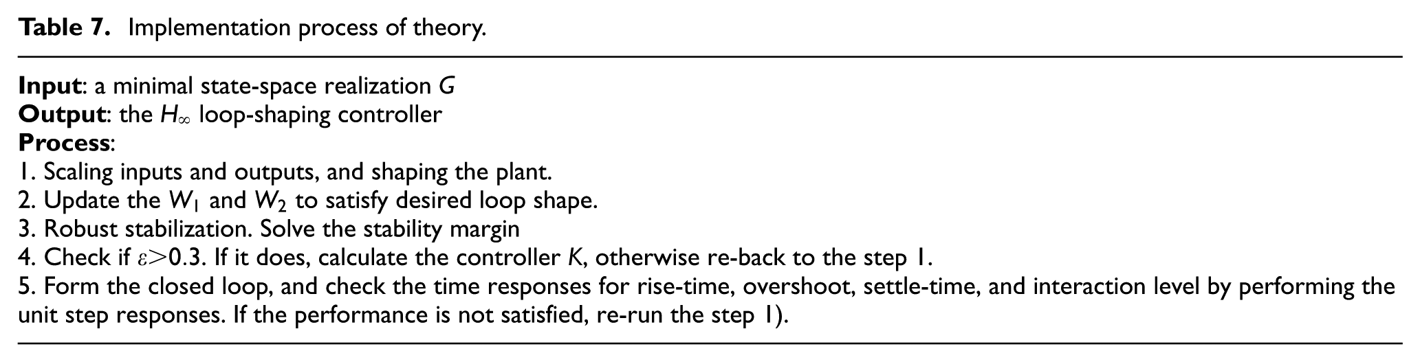
Based on the theory in section ‘Control theory’, the implementation process of the control law is presented in Table 7.
Implementation process of theory.
The ranks of


It shows that the state-space realization of the model is truly minimal realization. Therefore, the control synthesis can be implemented in the following procedure.
Input and output scaling
Each trim value was approximately chosen as the maximum allowable input to scale the responding input. 8 The output scaling process was based on the effectiveness of the open-loop responses and performance requirements. In this study, the selected output maximum scale value was high when the output singular response value was high. 33
Selecting pre- and post-compensators
The diagonal elements of pre-compensators are selected to boost a low-frequency loop gain and to reduce gain at high frequency. 29 The integral terms are chosen to improve the performance of the closed loop, such as the roll-off rate at cross-over frequency and the low-frequency gain, while the proportional parts adjust to the lead or lag phase. Altering pre- and post-compensators can seriously affect trade-off between robust stability and closed-loop performance. After numerous iterative trials, the pre-compensator is finally selected as follows

The diagonal elements of post-compensator are chosen as a constant in the following way

Controller synthesis and check time responses
Eigenvalues of the closed loop.
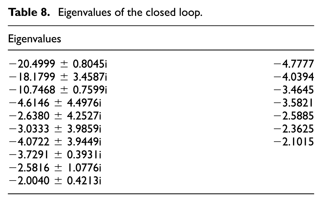
In Table 8, the real parts of eigenvalues are all negative. It shows that unstable model becomes stable after applying
Numerical simulations
Specifications
Guidelines for performance specifications were obtained from successful assessments of quality management of unmanned helicopters.9,29 Economic specifications were explored and developed to satisfy the requirements of controller design as follows:
Stability margin is larger than 0.3.
The overshoot of a step-time response is less than 20% and does not exhibit residual oscillation.
The decoupling and signal tracking are acceptable to a certain extent.
Therefore, these specifications are set as constraints to achieve sufficient control for our preliminary stage.
Performance analysis and discussion
According to the specifications, numerous iterative trials have been conducted to alter pre- and post-compensators until sufficient performances were achieved. Since couplings among six channels are complex, it must be considered carefully to achieve trade-off among the specifications for robust stability margin and performance.
A class of good nominal performances is illustrated in Figure 7, including small-overshoot, appropriate rise-time, satisfied settle-time and reasonable decoupling. Rise-times of the step responses of two variables are approximately 0.7 and 0.5 s, respectively. These achieved rise-times also agreed well with the bandwidth of the mode of mixed-rate pitch and roll. A slight residual couplings remain in velocities but being suppressed with the prolonging of time, as shown in Figure 7.

Step response on attitude: (a) pitch and pitch rate and (b) roll-roll rate.
In Figure 8, the step responses of the longitudinal and lateral velocities exhibit less overshoot, satisfied settle-time and reasonable decoupling. Rise-times of the step responses of longitudinal and lateral velocities are approximately 0.25 and 0.2 s, respectively. Rise-time tends to be faster than that the dynamic model bandwidth can handle. This phenomenon is mainly caused by high stability margin. It exhibits slightly higher overshoot but no oscillation. Satisfied decoupling is achieved.

Step response of velocity: (a) lateral velocity and (b) longitudinal velocity.
In Figure 9, step responses of the heave and yaw channels have a little overshoot but less than 20%. Rise-times of step responses of the heave and yaw variables are approximately 0.7 and 0.5 s, respectively. The perfect decoupling performance in the two channels is also similar to that of the attitude channel. In Figure 9, the couplings of step responses among the controlled variables are suppressed with the prolonging of time. The satisfied settle-times are also achieved, as shown in Figure 9. Based on experiences, altering pre- and post-compensators is a complicated task, particularly when settling six channels simultaneously to achieve a perfect trade-off.

Step responses of vertical and yaw velocities: (a) vertical velocity and (b) yaw rate.
In summary, the obtained stability margin is a perfect result to satisfy the performance specification (1). The overshoot of step response of each channel tends to calm. And they exhibit no residual oscillation in simulation results. Step responses of state variables also exhibit a perfect decoupling. And rise-times of step response are also reasonable. Moreover, the performance of achieved closed loop is relatively good although not perfect. Based on our experience, altering the pre- and post-compensators of a controller is a complicated task, particularly when settling six channels simultaneously to achieve a perfect trade-off. Adopting a hierarchical control structure provides a good idea on which possible solutions should be used to improve performance.
Conclusion
This article proposed a complete methodology for an unmanned coaxial rotor helicopter with unstructured uncertainties to achieve high-accuracy tracking performance from modelling to robust control. Conclusions are as follows:
A reasonable coaxial rotor helicopter prototype is constructed. This prototype has an ability to depict main characteristics of this type helicopter. Parameters agree well with experiments or empirical results from the open literature. In the parameter design, an empirical and verified process is implemented to decrease the budget and risk of programme. This design process can also contributed to other new rotorcraft design. Trim condition is calculated and analysed. Stability and control matrices are calculated through the quasi-steady assumption.
The
Simulation results show the effectiveness of the proposed controller for a coaxial rotor helicopter with unstructured uncertainties to achieve high-accuracy tracking performance. The resulting controller provided a stability margin of 0.3619. It means that tolerated sizes of a class of uncertainties are up to 36.19. Step responses exhibit no residual oscillation, an overshoot response of less than 20%, reasonable decoupling and good rise-time response. This proposed methodology can also be applied to address the high tracking performance of controller in the presence of unstructured uncertainties in other new type rotorcraft.
Footnotes
Academic Editor: Chenguang Yang
Declaration of conflicting interests
The author(s) declared no potential conflicts of interest with respect to the research, authorship, and/or publication of this article.
Funding
The author(s) disclosed receipt of the following financial support for the research, authorship, and/or publication of this article: This project is supported by National High Technology Research and Development Program 863 (No. 2013AA063903), the Chinese National Programs for High Technology Research and Development (No. 2009AA04 4403), the Doctoral Fund of Ministry of Education of China (Grant No. 20130061120038), Young Teacher Innovation Project of Jilin University of China (Grant No. 450060491425), China Postdoctoral Science Foundation (Grant No. 2014M560232) and Chinese National Natural Science Foundation (Grant No. 51505174).