
Abstract
Laser receiving system is an important part of laser fuze, but its working quality is very sensitive to severe overloading. As the common buffer isolation methods are difficult to apply in laser fuze receiving system, in this study, a high overload buffer isolation method of laser fuze receiving system is developed. Dynamic finite element analysis is carried out in ABAQUS for traditional and new buffer isolation solutions. Then, the effect of high overload on their optical response is evaluated with the ZEMAX software. Finally, a high overload impact test is performed. It can be seen that for the 70,000 g impact acceleration, the new buffer isolation method can reduce the impact load by about 10 times. Furthermore, the beam shaping quality of receiving system is comparable to that of the original beam without high overload.
Keywords
Introduction
Compared to traditional photovoltaic fuze, laser fuze has good proactive, strong direction and is less susceptible to electronic interference,1–3 which is widely used in the conventional ammunition.4–6 The laser fuze includes a receiving focus precision optical system. During functioning, the receiving system will sustain high overload. Especially during the launch of conventional weapons, the overload is very huge (≤70,000 g). In this case, due to the particularity of the material and the construction precision, the focal length and other optical parameters of receiving system will be changed while it is under high overload. Therefore, the laser fuze beam focusing quality will be affected seriously. 7
In order to ensure the normal operation of laser fuze component in the bomb, generally, there are three ways to reduce the emission overload of conventional ammunition: (1) to change ballistic performance parameters, (2) to optimize the component structure for improving resistance to impact, and (3) to design the vibration isolation system for reducing impact load. 8 Due to the overall performance of the weapon system constraints, there is little room for adjustment of the ballistic parameters; strategy (2) has certain effect, but it is limited by structural performance requirements;9–11 strategy (3) can design the buffer isolation system through the choice of parameters and materials. However, since the space of conventional ammunition laser fuze optical receiver system is limited, it is difficult to arrange the buffer isolation system to reduce the transmission overload.12–15
In order to improve the beam shaping quality of the receiving system by reducing the plastic deformation caused by high overload, a method of buffering vibration isolation for laser fuze optical receiving system is presented in this article. Integration technology of receiving focusing lens, narrowband filter, and outer cylinder is studied. Then, the buffer isolation performance under different conditions is analyzed. Based on the study mentioned above, a new type of laser fuze buffer vibration isolation system is designed. The nonlinear dynamic response of the traditional and new buffer systems is compared for the case of 70,000 g overload using the ABAQUS finite element (FE) program. The plastic deformation of focal lens is determined and the optical response of the receiver lens is analyzed with the ZEMAX software in order to evaluate changes of focusing quality of receiving lens. Finally, experimental tests reproducing impact conditions are performed to check the effectiveness of the new buffer method. This study provides a reliable and easy method for studying laser fuze resistance to severe overloading.
Overview of laser fuze optical receiving system
In the laser fuze, the echoes of the target are converged by the optical receiving system. Then, the echoes are irradiated to a photo sensor such as a photodiode (PIN) or an avalanche photodiode (APD). Finally, the optical signal is converted into electrical signal and sent to a subsequent processing circuit for processing. The shaping quality of laser echo directly affects the reliability of the system. 16
Laser fuze receiver module requires small size, light weight, and high light transmittance. Furthermore, it requires a small coefficient of expansion of the material, high mechanical strength, impact resistance, and long service life. Because epoxy resin has good mechanical properties, heat resistance, and cold resistance, it can maintain high mechanical strength in a wide temperature range (−135°C to 120°C).17,18 Furthermore, since its optical properties are excellent, epoxy resin has been selected as the material for lens in this study.
The outer cylinder material of laser fuze receiving system is made of hard aluminum. The system is shown in Figure 1. The receiving lens (the aperture is 18 mm, the entrance pupil diameter is 14 mm, the thickness is 4.2 mm, the receiving field angle is 8°) is fixed on the outer cylinder by the annular pressing ring, the narrowband filter (the thicknesses is 4 mm, the diameter is 20 mm) is fixed by the pressing ring, and the bakelite mats, the photosensitive sensor, and the follow-up processing circuit are located in the outer cylinder. Polymer materials, such as silicone rubber, epoxy, or polyurethane, are used to fix the location of various components.

Structure of laser fuze receiving system.
When subjected to high emission overloads, due to the great inertia, the receiving focus lens and the narrowband filter are plastically deformed by interacting with the annular press ring, the outer cylinder, and the bakelite pad. As the laser fuze receiving system is rigorously calculated, the plastic deformation will have a serious impact on the focusing optical path and the convergence quality of the echo beam.
Nonlinear dynamic FE simulation of focusing lens in laser receiving system
Nonlinear dynamic model of focusing lens
The dynamic behavior of the laser receiving system subject to high overloading is simulated with ABAQUS. The FE model includes 8-node 3D Solid 164 elements. As the structure is symmetrical, a 1/4 model is considered in order to save computation time. The regions between focus lens and outer cylinder and between narrowband filter and pressure ring are properly refined to capture stress concentrations. The junctions between pressure ring, bakelite mats, and outer cylinder are modeled using the restraint tie option. Since focusing lens is fixed by the pressing ring and the outer cylinder step, the region between the end face and the pressing ring and the outer tube step is defined as a small sliding area. Since there is a gap between the focusing lens and the inner diameter of the outer cylinder, this region is modeled with the hard contact option. Details of FE model developed for the traditional laser receiving system are shown in Table 1. Convergence analysis was carried out in order to obtain mesh-independent solutions.
Details of FE model of the traditional laser receiving system.

FE: finite element.
The strain rate effect and the failure should be considered when the laser fuze receiving system is subject to a high acceleration. Here, the ELASTOPLASTIC kinetic model * MAT_PLASTIC_KINEMATIC is used, by adjusting the hardening parameter β from 0 (kinematic hardening only) to 1 (isotropic hardening only) to select isotropic or kinematic hardening. Cowper–Symonds model is used to analyze strain rate. The following expression relates the yield stress with strain rate factors

where

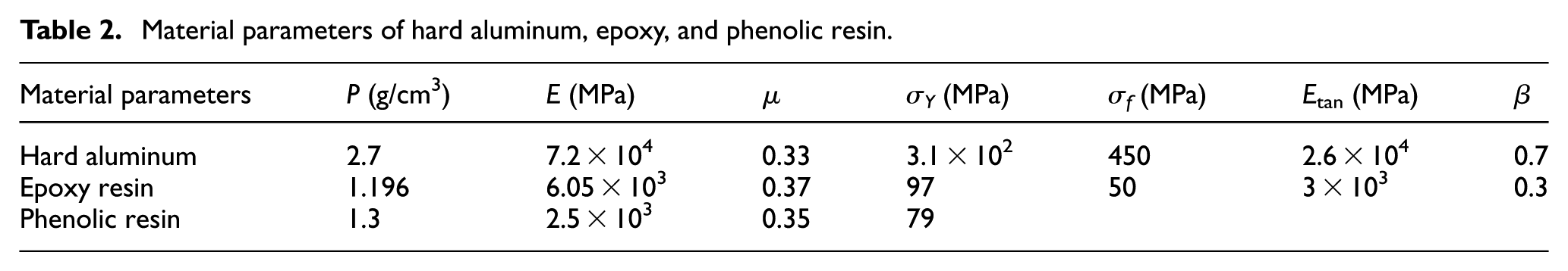
Table 2 presents the mechanical properties of the different materials included in the laser fuze structure: ρ is the material density, E is the elastic modulus, µ is Poisson’s ratio, and Etan is the shear modulus.
Material parameters of hard aluminum, epoxy, and phenolic resin.
A 70,000 g impact acceleration is applied to the outer cylinder. The FE analysis covers a total time of 12 ms. The CONTACT_ERODING_SURFACE_TO_SURFACE option is selected for contact surfaces. The load curve is shown in Figure 2.

Curve of launch load-time.
Nonlinear analysis of traditional laser fuze receiving system
Figure 3 shows the FE model of the standard laser fuze receiving system. Figure 4(a) shows the distribution of maximum effective strain developed in the focusing lens of the conventional laser receiving system after 12 ms. Figure 4(b) shows the evolution of strain at four nodes of the FE model (6, 328, 28, 535) located in the front and rear ends of receiving lens. The nodes’ positions are shown in Figure 4(a). It can be seen that the maximum effective strain developed in the lens front is 0.0638, while the maximum effective strain developed in the rear end is 0.0752. Since these strains are larger than 5% of axial thickness, they may have a serious impact on the laser focusing system.

The finite element model of the standard laser fuze receiving system.

(a). Distribution of maximum effective strain developed after 12 ms in the receiving lens subject to impact. (b) Time variation of effective strain evaluated at four control points.
Figure 5(a) shows the strain distribution computed by ABAQUS for the narrowband filter again at 12 ms. The time evolution of strains at four nodes of the model (9, 427, 32, 233), located in the front and rear ends of the filter, is shown in Figure 5(b). The nodes’ positions are shown in Figure 5(a). It can be seen that maximum strains developed in the front and rear ends of the filter are 0.0541 and 0.0642, respectively. Since those strains again are larger than 5% of the axial thickness, they may seriously affect the laser filtering process.
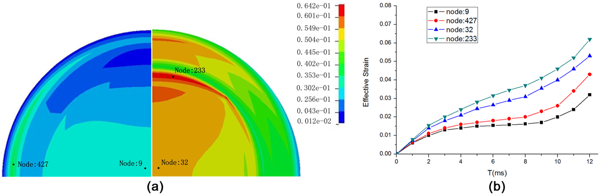
(a). Distribution of maximum effective strain developed after 12 ms in the narrowband filter subject to impact. (b) Time variation of effective strain evaluated at four control points.
Nonlinear analysis of integrated laser receiving system
Potting technology is usually used to improve the impact resistance of printed circuit board and other brittle components. However, due to the special nature of optical materials of laser receiving system, this technology cannot be used. In order to further enhance the strength of the laser transmitter module, integration technology of receiving focus lens and narrowband filter is chosen, which can reduce the original parts, reduce the weight of the transmitting system, and simplify the system structure. The receiving focusing lens and narrowband filter integrated system (the aperture is 18 mm, the entrance pupil diameter is 14 mm, the thickness is 4.2 mm, and the receiving field angle is 8°) are shown in Figure 6. Details of FE model developed for the integrated laser receiving system are shown in Table 3. Convergence analysis was again carried out in order to obtain mesh-independent solutions.
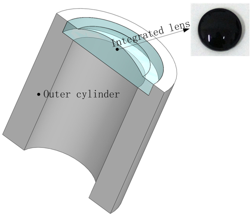
Integrated laser fuze receiving system developed in this study.
Details of FE model of the integrated laser receiving system.

FE: finite element.
Similar to the traditional fuze case, an impact load of 70,000 g lasting 12 ms was applied to the outer cylinder. Figure 7 shows FE model of the integrated laser fuze receiving system. The strain distribution computed by ABAQUS is plotted in Figure 8(a). Figure 8(b) shows the time evolution of maximum effective strain at four control nodes (12, 486, 26, 698), located in the front and rear end of the lens system. The positions of these nodes, close to the control nodes considered in the previous analysis, are shown in Figure 8(a). The maximum effective strain developed in the lens system is 0.00532, much less than 5% of the lens axial thickness. Hence, the strain developed in the integrated receiving system does not affect significantly the behavior of the laser focusing system.

The finite element model of the integrated laser fuze receiving system.

(a) Distribution of maximum effective strain developed after 12 ms in the integrated laser fuze receiving system. (b) Time variation of effective strain evaluated at four control points.
Optical simulation and analysis of focusing lens in laser receiving system
The focusing effect of the receiving system under different shock conditions is simulated using ZEMAX (an optical system analysis software). The system focal length is 20 mm, aperture is 18 mm, the approximate spherical radii of the receiving lens are 13.64 and 192.36 mm, and the thickness is 4.2 mm. The narrowband filter has a diameter of 20 mm and a bandwidth of 100 nm.
Figure 9(a) shows the original spot, and Figure 9(b) is the spot focused by receiving lens. Figure 9(c) and (d), respectively, shows the spots which are focused by traditional and new optical receiver systems. It can be seen from Figure 9(a) that the original spot is large and the energy is divergent, and the central irradiation brightness is 8.46 × 10⁻⁴ W/cm2; the spot energy is concentrated after having been focused by the aspheric receiving lens (see Figure 9(b)), the central irradiation brightness reaches 8.1824 W/cm2, and the spot size is obviously reduced. After having been impacted by the high overload, the spot light energy of the aspherical focusing lens diverges (see Figure 9(c)), the spot size is not uniform, and the center irradiance is reduced to 0.7836 W/cm2. However, after having been buffered by the new optical system, the focal spot energy of the focusing lens and the narrowband filter lens is equal to the pre-impact focal spot, and the central irradiance is 7.9018 W/cm2 (see Figure 9(d)). Thus, the new type of buffer structure of the laser receiver system can effectively reduce the lens plastic deformation and improve the optical system efficiency.

Sectional views of far-field spot for traditional and novel laser fuze structures: (a) the original spot before focusing, (b) the spot after focusing, (c) focused spot for the traditional structure subject to overloading, and (d) focused spot for the new structure subject to overloading.
High overload dynamic experiment of focusing lens in laser receiving system
In order to verify the effect of high emission overload on the shape of the beam focused by the laser receiving system, a high overload impact test is carried out in the laboratory. The schematic of shock table is shown in Figure 10. The air compressor is fed by the air pump to the base. As pressure reaches a proper value, the impact table is released and hits the base through the slide rail, thus generating the acceleration overload. The load is acquired by an acceleration detection module embedded in the impact table. The receiving lens is fixed to the top of the impact table by a fixture. The impact parameters are set as follows: the pressure is 100 MPa, the height is 13 cm, the gasket comprises two layers, the number of impact cycles is 1, the corresponding impact acceleration is about 70,000 g, and the impact time is about 13 ms. This can simulate the high overload of actual projectile firing environment. The actual overload acceleration curve is shown in Figure 11. The performance of the focusing system is experimentally evaluated for the traditional and new laser fuze systems.
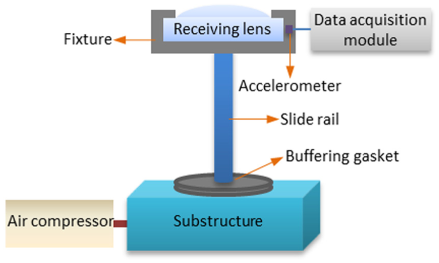
The schematic of shock table.

The actual overload acceleration curve.
The principle of the optical circuit is schematized in Figure 12. The optical setup used in the experiments exactly reproduced the geometry of the laser fuze structures analyzed by ABAQUS and ZEMAX. Measured spots are shown in Figure 13(a)–(d). It can be seen that after the impact of high overload, the spot energy focused by traditional laser receiving system has a serious attenuation, the spot size increases, and the energy diverges; the laser pulse energy and spot size of the new optical buffering receiving system are almost equal to those before the impact. This result is consistent with theoretical analysis and numerical simulations. Hence, the proposed design solution can effectively improve the receiving system against high overload performance and ensure system reliability.
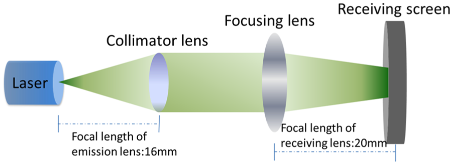
Schematic of the optical circuit utilized in the experiments.

Laser beam profile across the laser fuze optical system: (a) original spot, (b) collimated spot before overloading, (c) focused spot by receiving lens for traditional laser fuze structure subject to overloading, and (d) focused spot by receiving lens for the new laser fuze structure subject to overloading.
Conclusion
This study presented a novel laser fuze receiving system integrating the receiving lens, the narrowband filter, and the outer cylinder. The ABAQUS FE program simulated the nonlinear structural response of the receiving system to a 70,000 g impulse acceleration simulating the firing phase. It was found that the integrated structure undergoes small deformations that marginally affect the profile of the laser beam traveling across the fuze optical system. The simulations carried out with the ZEMAX software demonstrated that the proposed solution can effectively improve the quality of beam focusing and shaping. In particular, the focused beam keeps its energy throughout the optical circuit. It should be noted that the structural model was not experimentally validated. However, the deformation field computed by ABAQUS is perfectly consistent with the beam intensity fields measured for the traditional and new laser fuze structures. In summary, the new design greatly simplifies the system structure, significantly improves the quality of laser focusing, and reduces the impact of high overload on the receiving system. This may offer new solutions to the study of anti-high-overload of conventional weapon laser fuze.
Footnotes
Academic Editor: Filippo Berto
Declaration of conflicting interests
The author(s) declared no potential conflicts of interest with respect to the research, authorship, and/or publication of this article.
Funding
The author(s) disclosed receipt of the following financial support for the research, authorship, and/or publication of this article: This study was supported by National Natural Science Foundation of China (51605227) and the Fundamental Research Funds for the central Universities (NUST30915011303).