
Abstract
The rotor-bearing system is a crucial component of rotating machinery, such as turbines, pumps, compressors, and turbogenerators, which are widely used in various advanced engineering fields. This work presented a methodology for studying the behavior of an elastic Jeffcott rotor supported by two similar fluid film journal bearings. A finite element model using consistent matrix formulation was employed to simulate the shaft, including the external load, with four degrees of freedom per node. The small perturbation method was used to evaluate the second-order bearing coefficients of a journal bearing of finite length. These coefficients were further integrated with the finite element model to evaluate the dynamic response of the flexible rotors. Moreover, the system equations of motion were presented in dimensional form. The results of the second-order bearing coefficients analysis agreed with nonlinear analysis when the speed was less than the threshold speed, while there was a pronounced difference in second-order analysis when the speed was above the threshold speed. The behavior of the rotor-bearing system was studied using dynamic response and orbit diagrams, revealing that changes in rotational speed significantly affected the rotor’s stability.
Keywords
1. Introduction
The rotor-bearing system is a critical component used in a variety of industrial applications, including turbomachinery, power stations, machine tools, automobiles, household appliances, aerospace applications, marine propulsion, and medical equipment (El-Sayed and Abdel Fatah, 2016; El-Sayed and Farghaly, 2016; Tiwari, 2017). In modern machinery, improving efficiency is crucial for reducing energy consumption. This can be achieved by increasing the speed of the rotating parts while simultaneously reducing their weight. However, it is equally important to ensure that stability is maintained under these conditions. Fluid film bearings that support rotating shafts are used in rotor-bearing systems because of their simplicity, low cost, silent operation, long life, and high radial precision. These bearings rely on a fluid film between the rotor and the bearing to carry the load while allowing the rotation of the rotor. Fluid film bearings build up pressure inside the bearing clearance because of the fluid’s viscosity and the rotor and bearing’s relative velocity. As the rotor speed increases, the generated pressure gradually increases until it reaches a level where it is able to fully sustain the load of the rotor. Dynamic rotor-bearing systems can undergo unsteady vibrations due to inadequate management, resulting in catastrophic failures. Lubricated bearings, asymmetric stiffness of the shaft, internal friction between mating parts, and other factors can all cause internal instabilities in rotor-bearing systems. Amplitude peaks are recorded when the rotor is run close to its critical speed due to the inherent unbalance present in the rotor-bearing system. In the present work, the behavior of a flexible rotor supported on two similar fluid film journal bearings has been addressed.
1.1. Rotor-bearing system instability
The instability of rotor-bearing systems is a critical concern in various engineering applications, as it can lead to performance degradation, excessive vibrations, and potential failure. Understanding and analyzing the factors contributing to rotor-bearing system instability is essential for ensuring the safe and reliable operation of rotating machinery.
Many studies focus on an approximation method of bearing forces using linear first-order bearing coefficients, while others concern with higher-order bearing coefficients approximations (El-Sayed et al., 2023; Elsayed et al., 2023; El-Sayed and Sayed, 2022; Sayed and El-Sayed, 2022, 2022b). Such approximations simplify the system and enable the investigation of its stability. A hydrodynamic journal bearing stiffness and damping coefficient can be obtained using Taylor expansion of the bearing forces. These damping and stiffness bearing factors are utilized to calculate the forces and examine the dynamics of the bearing system. El-Sayed and Sayed (2022) applied the perturbation method to obtain the third-order bearing coefficients for a journal bearing with a finite length. A Jeffcott rotor mounted on two similar lubricated bearings is investigated using these coefficients. Miraskari et al. (2018) conducted a study on the stability of nonlinear flexible rotors supported by finite-length fluid film bearings. They proposed a mathematical model for the flexible Jeffcott rotor-bearing system, where the bearing forces were expressed using first- and second-order approximation bearing coefficients. It was found that models incorporating bearing coefficients exhibited significantly improved agreement with experimental setups in identifying instability regions. Moreover, the nonlinear system revealed that the unbalance trajectories can capture sub-harmonics and super-harmonics which are absent from linear trajectories.
Phadatare and Pratiher (2016) conducted an investigation into the nonlinear frequencies and dynamic behavior of high-speed rotors, taking into consideration the effects of gyroscopic forces and unbalanced mass. The primary objective of their study was to identify the operational speed zones that could lead to excessive vibration, in order to avoid such occurrences. Kakoty and Kalita (2002) studied the stability of rotors supported on hydrodynamic journal bearings. The study aimed to determine the stability characteristics of the rotor-bearing system based on bearing geometry and viscosity. In addition, the stability behavior of rotors supported by rigid and flexible bearings (circular and noncircular) is investigated. Holmes (1980) studied theoretically and experimentally the mechanism of oil whirling causing instability in rotors and found that a small amount of external damping at the shaft span increases the instability speed and affects the instability control. Hagg (1946) described oil-film whirl or oil whip that is induced by the lubricating films of journal bearings, and it has been observed that, in the general case, the peak whirling frequency is equal to one-half rotational frequency. Lund (1974a, 1974b) described a method for calculating the threshold speed of instability of a flexible rotor supported by lubricated journal bearings. The bearings are represented by their linearized dynamic stiffness and damping coefficients. These bearing coefficients are established to calculate hysteretic internal damping in the shaft and aerodynamic forces.
Muszynska (1986, 1988) proposed a mathematical model of a symmetric unloaded rotor supported by two bearings, one rigid and the other fluid film bearing. Using this model, the self-excited and synchronous vibrations due to rotor unbalance are studied. Additionally, the stability of the rotor vibrations is investigated. Rao (1985) studied the dynamic behavior of a rotor mounted in fluid-lubricated bearings and was concerned with the instability of the rotor that occurs when a bearing’s cross-coupled stiffness coefficient has a negative value. It also demonstrated that this instability occurs in a confined rotor speed range. Pai and Majumdar (1991) carried out a nonlinear analysis of a rigid rotor mounted by two hydrodynamic bearings under constant load to predict the critical speed of stability. In addition, they obtained bearing hydrodynamic forces by solving the Reynolds equation using a finite difference method. Kirk and Gunter (1976a, 1976b) investigated the transient response of rotors mounted in lubricated bearings. They used the short bearing model to show the effect of imbalance, steady loading, and rotating loads upon stability and performance. Zhao et al. (2005) simulated the journal and disk motion using the fourth-rank Runge-Kutta method for a symmetrical single-disk flexible rotor-bearing system. Moreover, linear and nonlinear hydrodynamic forces are used for computing unbalanced responses. De Castro et al. (2008) modeled a nonlinear hydrodynamic flexible rotor under unbalanced excitation and studied the effect of horizontal and vertical rotor arrangement on the instability. The results of this model are compared with measurements of a real power plant. El-Shafei et al. (2007) studied the effect of various conditions such as pressure, misalignments, and unbalance on the instability of the rotor mounted on two plain cylindrical journal bearings. Results show that the misalignment is the most effective on the instability of the rotor. Newkirk and Taylor’s (1925) investigation focused on shaft whipping, also known as oil whirling, which occurs at speeds above the critical speed of the rotor. Their findings demonstrated that oil whirling only occurs at running speeds approximately twice the rotor’s critical speed or higher. Tieu and Qiu (1995) conducted a study on the relationship between instability and bearing forces, comparing the results of linear and nonlinear analyses. Their investigation also included an examination of the differences in whirl loci, whirling trajectories, position perturbation, and synchronous unbalance excitation between the two types of analyses.
1.2. Rotor-bearing system nonlinear analysis
The dynamic behavior of a rotor-bearing system is significantly impacted by the presence of unbalanced masses in rotating discs and nonlinear forces induced by the fluid film. Additionally, further nonlinearity can arise from the rotating disc itself, as demonstrated in studies such as (Pal and Das, 2022; Zeng et al., 2019). Miura et al. (2017) conducted a theoretical analysis to investigate bifurcation phenomena and nonlinear behavior in a rotor mounted by two circular bearings. They employed a third-order polynomial approximation model to represent the oil film forces.
Wang et al. (2013) investigated the nonlinear characteristics of a rub-impact rotor-bearing system supported by oil film journal bearings. Their study included the analysis of bifurcation, frequency spectrum diagrams, Poincaré maps, and vibration responses of the rotor. The results demonstrated the efficiency of their applied method in understanding and controlling nonlinear dynamic behaviors. Forsat (2020) investigated the nonlinear vibration of hyper-elastic beams and studied four models. Their results showed that one of these models is suitable for nonlinear vibration analysis and frequencies. Yang et al. (2014) applied a partial derivative method to obtain the second-order bearing coefficients for a journal bearing with a finite long and infinite short bearings. They used this model to analyze the nonlinear performance of a symmetrical flexible rotor-bearing system. The results proved that this model is successful in predicting the nonlinear behavior of the system.
Shen et al. (2008) performed theoretical and experimental investigations to analyze nonlinear behavior in a Jeffcott rotor-bearing sealed system. They solved a nonlinear governing equation to obtain rotor orbits, waterfalls, and bifurcation diagrams, providing a comprehensive understanding of the rotor’s nonlinear phenomena. Theoretical and experimental results exhibited favorable agreements. Song et al. (2022) solved the unsteady Reynolds equation at ultra-shaft speed to obtain the rotor orbits for hybrid air-bearing rotor design. Moreover, the effect of unbalanced rotor mass, speed, and external loads on the nonlinear behavior of the rotor has been investigated.
Jia et al. (2022) developed a non-probabilistic convex model to characterize uncertain parameters in the Jeffcott rotor system. They introduced the Chebyshev Convex Method (CCM) using non-embedded Chebyshev expansion functions. Rotor responses were calculated using the CCM when both mass and bearing stiffness were unknown. Myers (1984) solved the nonlinear equation of the rotor system mounted by two similar lubricated journal bearings. This solution focused on rotor speeds near the steady-state equilibrium position, highlighting the Hopf bifurcation and instability zones. Shi et al. (2013) investigated the nonlinear response of a vertical rotor-bearing system by considering the effects of nonlinear bearing forces. Their study utilized rotor orbits, waterfalls, bifurcation diagrams, and frequency spectra to comprehensively analyze the nonlinear dynamic behavior of the system. Noah and Sundararajan (1995) produced analytical and computational techniques to investigate the critical effect of nonlinear rotor-dynamics on industrial rotating machines. They obtained new results in the nonlinear behavior of the rotor supported in lubricated bearings.
Adiletta et al. (1997) investigated the nonlinear behavior of an unbalanced rigid rotor mounted by two plain journal bearings using short bearing approximation. Kim and Noah (1990) carried out two advanced techniques (Harmonic Balance HB/Alternating Frequency Time AFT) to obtain synchronous and sub-synchronous whirling motion of a rigid rotor with two plain bearings. They used a perturbation equation to get the steady-state motion and stability conditions. Chen and Yau (1998) presented a nonlinear dynamic model of a flexible rotor associated with lubricated journal bearings. The bearing center was analyzed using a bifurcation diagram and power spectra under different operating conditions in a horizontal and vertical direction. Holt et al. (2005) studied linear and nonlinear dynamic analysis of small automotive turbocharger supported by two floating bearings. Wang et al. (2002) used pressurized gas journal bearings to study the nonlinear dynamics of a flexible rotor. They demonstrated the influence of Sommerfeld bearing number and rotor mass affected rotor dynamics. Lin et al. (2023) studied the characteristics of water film in the hydrodynamic journal bearing using nonlinear analysis. Furthermore, they investigated the influences of eccentricity, pressure of water film, external load, and inertia force. Results show the importance and effect of considering inertia force on the water film pressure.
1.3. Finite element method in rotor dynamics
In this section, the analysis of the dynamic behavior of the rotor and the investigation of its vibration characteristics are carried out using finite element method. The finite element method is highly customizable and effective in analyzing rotor-bearing systems, especially when they are large and complex.
Lien-Wen and Der-Ming (1991) developed a mathematical model based on Timoshenko beam theory to investigate the effects of bending and shear force deformation, gyroscopic forces, and rotary inertia on a rotating shaft subjected to whirling speeds. The model was verified using an industrial high-speed compressor, demonstrating its practical applicability. Results indicated good agreement between the model predictions and experimental data. Numanoğlu et al. (2022) conducted a vibration analysis of nanobeams using Hamilton’s principle based on Timoshenko beam theory. Due to the complexity of the problem, they employed a finite element method to obtain local and nonlocal stiffness and mass matrices since these matrices could not be analytically solved. Their study focused on the importance of using nonlocal finite element methods to analyze the vibration behavior of nanobeams. Chen (1996) studied the stability bounds and instability threshold of a flexible rotor-bearing system. The system’s equation of motion was calculated using FEM. Chen (1996), Manfrida and Martelli (1980) verified the results of Chen’s model with the approximate analytical model. Rouch and Kao (1980) developed a reduction in finite element matrixes that are used to analyze flexible rotor-dynamics, this helps in the reduction of the computational time of the system and improving modeling accuracy.
Nelson (1980) employed a finite element method to simulate a rotor-bearing system. In addition, the study examined the impact of damping parameters, rotary inertia, and external loads on the stability of the rotating shaft. Furthermore, the study verified the outcomes of the model through comparison with the classical closed-form Timoshenko beam theory. Ozguven and Ozkan (1984) analyzed the effect of dynamic parameters such as internal viscous damping, gyroscopic and rotary inertia, and axial force on rigid rotors supported by bearing clearances. In addition, they calculated the response, backward, and forward whirling speed of the rotor using a computer program. Khulief and Mohiuddin (1997) reduced the order of the rotor finite element model using the modal truncation method. Their model truncation was divided into a complex and planer model to assist analysis of rotor dynamics.
Jianping et al. (2004) performed a nonlinear analysis of the rotor associated with a journal bearing using a continuum model. In addition, they analyzed bifurcation plots of oil whip phenomena and recommended a careful investigation of the nonlinear dynamic response of the rotor-bearing system. Liu et al. (2007) utilized the advanced Newmark β method to derive an equation of motion for the generator-bearing system. Additionally, the study examined the effects of oil viscosity, slenderness ratio, and unbalance force on the instability and dynamic response of the system. Hong and Park (1997) proposed an effective method to analyze unbalanced responses of multi-span rotor-bearing systems. The study also utilized several test examples to validate the proposed results. Yang and Lin (2002) provided finite element analysis to investigate the balancing of a rotational shaft. Numerical validation of this method is presented, and examples are given to show the effectiveness of the identification method.
The above literature shows that few studies used the higher-order bearing coefficients while using finite element model. So, in this work the second-order bearing coefficients are evaluated using infinitesimal perturbation method, and dimensional model is developed to simulate a real application. The aim of this work is to solve the rotor-bearing system using finite element method to study the effect of changing number of elements and using different shaft diameters on the rotor-bearing system behavior. Moreover, the study examines the effect of unbalance force and shows the synchronous vibration oil whirl. After this introduction, in Section 2, the Reynolds equation is solved using a mathematical model to determine the second-order bearing coefficients, which are then used to obtain the responses and trajectories of the rotor-bearing system through the finite element method. Section 3 presents a comparison of the model results with those found in the literature, as well as the new findings and results of the study. Lastly, the Conclusion section summarizes the study’s key findings and highlights the significant benefits of the model results.
2. Rotor modeling using FEM
This section explores the finite element method as a means to determine the rotor’s behavior and dynamic response. The finite element method is one of the most often used methods in rotor dynamic analysis. The analysis of finite elements may utilize three potential beam models: Euler-Bernoulli, Rayleigh, and Timoshenko beams. The three theories use a plane cross-sectional area with an elastic axis perpendicular to the area. The main difference between the three theories is that the first one considers only pure bending, the second considers translational kinetic energy, rotary inertia, while the third one includes shear strain and rotary inertia. Euler-Bernoulli beam theory can be seen as simplifications of the Timoshenko beam theory. In this paper, we utilized Euler-Bernoulli beam elements since they are valid for long and slender shafts, but do not account for shear deformations, which can significantly influence the lateral response of thick shafts. This work is based on the following assumption: • The hydrodynamic journal bearings are modeled by a set of bearing coefficients. • The Jeffcott rotor is supported with two symmetrical hydrodynamic lubricated bearings. • The dynamic modeling included the gyroscopic effect. • Torsional and axial vibrations are not considered.
2.1. Characteristics of journal bearings (solution of Reynolds equation)
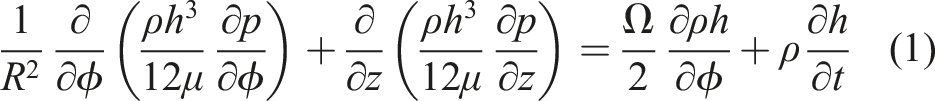
For the fluid film journal bearing shown in Figure 1(a), the pressure in the oil film is estimated by solving the following Reynolds equation. Schematic of circular shape journal bearing: (a) schematic of a perturbed journal inside bearing with angular and cartesian coordinates, (b) mesh of the oil film, and (c) nodes for the half-step finite difference method.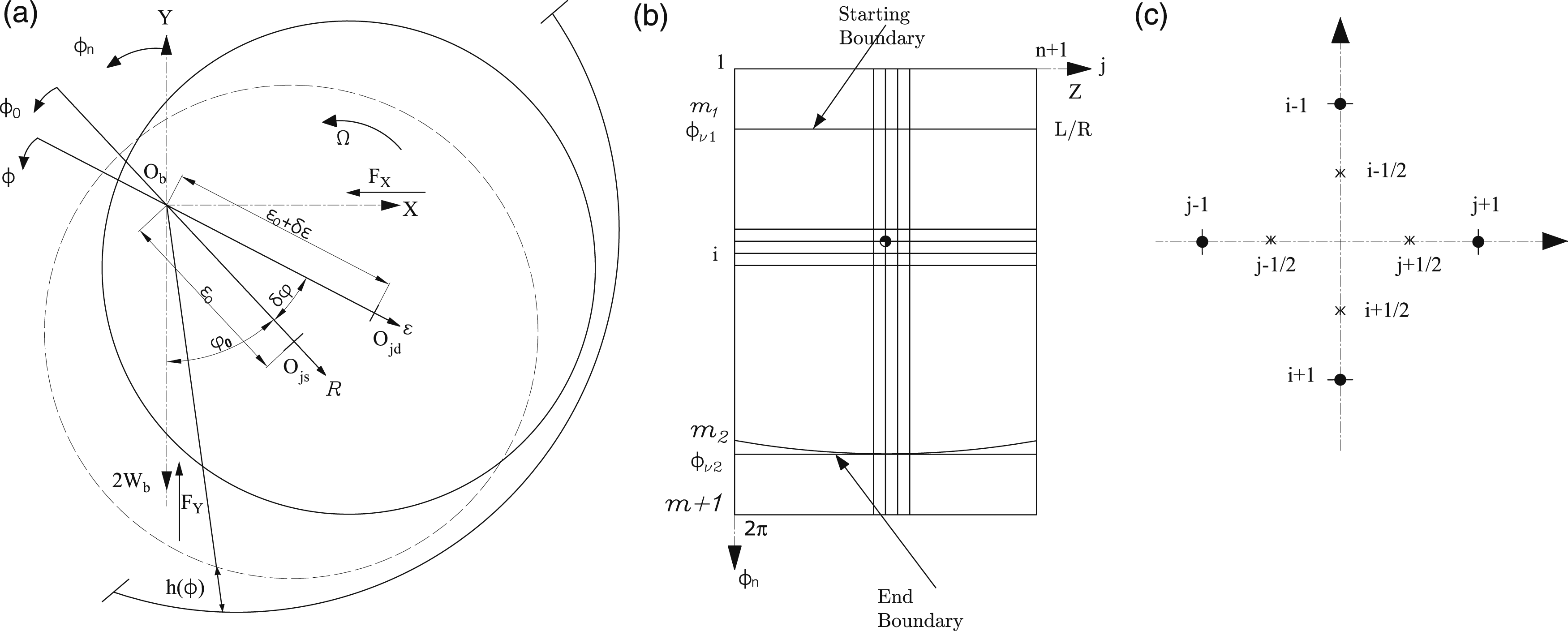

For small value of δφ it can substitute with

The circumference angle, measured from Y-axis, is denoted as ϕ
n
= ϕ0 + φ0 as shown in Figure 1
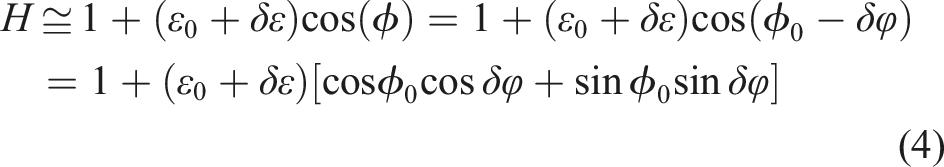
To convert the oil film thickness coordinate in equation (7) from polar coordinates to cartesian coordinates, Figure 1 is employed. By referring to Figure 1(a), we can establish the following relationship.
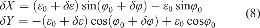
Through careful mathematical rearrangements and the reduction of higher-order terms, equation (8) can be transformed into a more concise matrix representation, as demonstrated below:
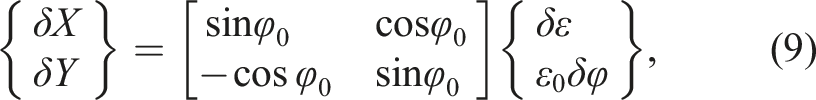
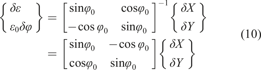
By substituting equations (8–10) into equation (7), the first-order approximation of the perturbed oil film thickness in terms of cartesian coordinates can be written as:

2.2. Second-order dynamic bearing coefficients in cartesian coordinate X−Y
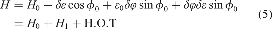
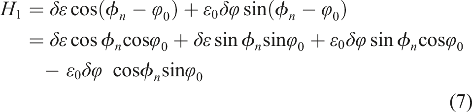
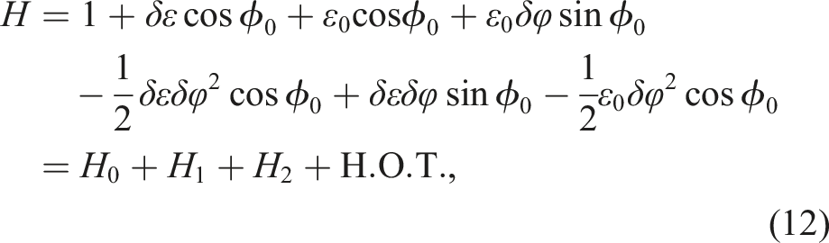
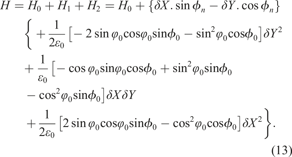
To obtain a more precise approximation for the thickness of the oil film, the second-order terms resulting from the expansion of equation (4) are considered. This approximation assumes that the deviation δφ from the equilibrium angle is small, allowing for the use of the approximations cos(δφ) ≈ 1 − 1/2δφ2 and sin(δφ) ≈ δφ. Additionally, the substitution of ϕ0 with ϕ
n
− φ0 simplifies the equation into a more convenient form.
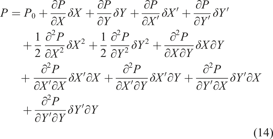
The perturbation in oil film thickness causes a corresponding perturbation in the induced journal pressure. This perturbed pressure can be expressed as a function in journal position and velocity:
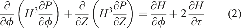
To estimate the steady-state pressure using the Reynolds equation (2), the half-step finite difference method is utilized to calculate the derivative of oil film thickness and pressure.
2.3. Nonlinear bearing forces second-order approximation
The dimensionless bearing forces in the X and Y directions are calculated using a second-order Taylor series expansion. The resulting expressions for the dimensionless bearing forces are given by: Rotor-bearing system with elastic rotor: (a) rotor-bearing schematic and (b) system coordinate.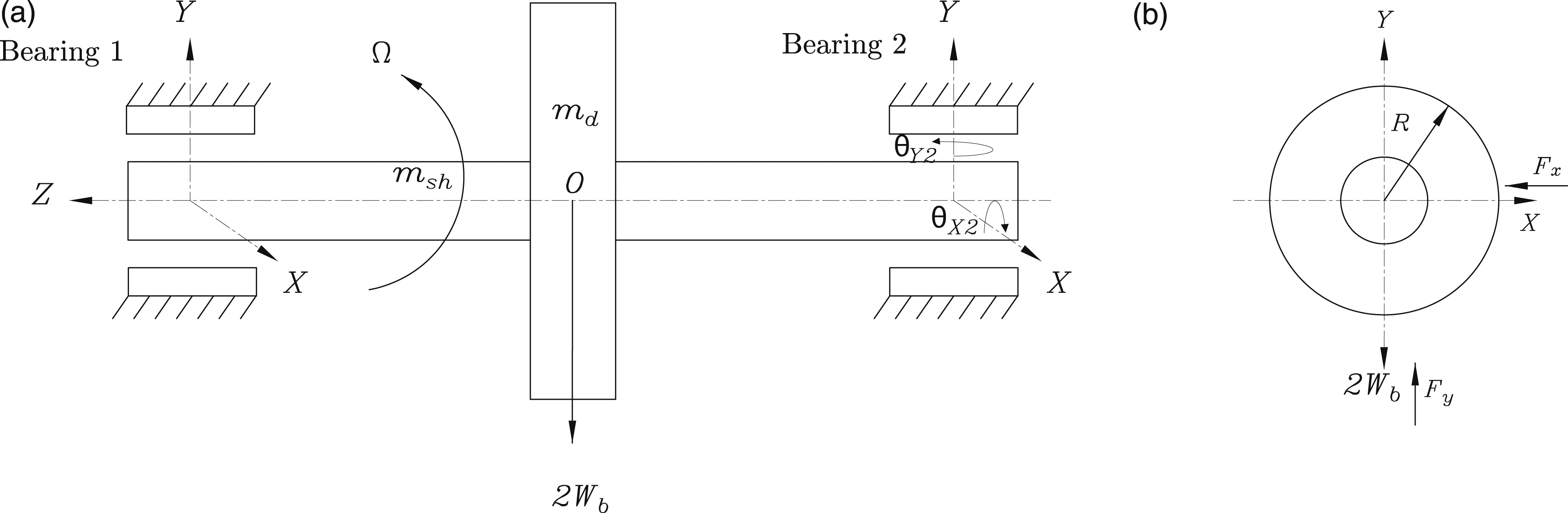
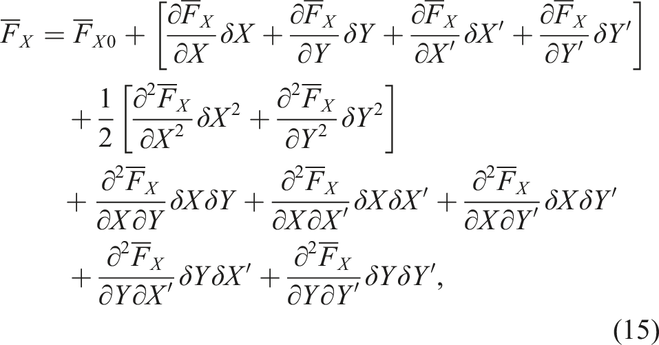
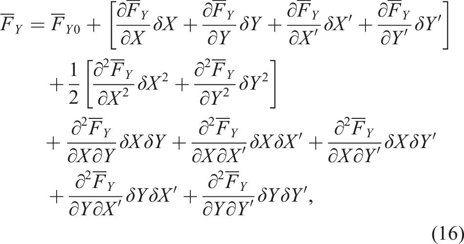
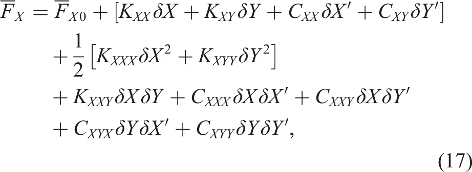
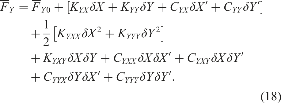
To express the dimensionless bearing forces in terms of the stiffness and damping coefficients of first- and second-order approximation, the equation can be rewritten as follows:
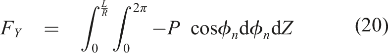
To calculate the dimensionless bearing forces F
X
and F
Y
, following equations are used:

The bearing forces in the dimensional form can be introduced as:

Now, the eight linear bearing coefficients of stiffness and damping, as well as the 14 nonlinear bearing coefficients, can be obtained. The equations used for obtaining these coefficients are listed in Appendix C. After solving the integration equations using MATLAB code, the dimensionless stiffness and damping coefficients are obtained. These coefficients can then be used to calculate the dimensional stiffness and damping coefficients using equation (21).
2.4. A rotating shaft’s formulation using finite elements
Figure 3 shows a sample of a rotating shaft, which is assumed to be straight and have uniform circular cross-section with two nodes (one on each end). Each element of the shaft has eight degrees of freedom, with four at each node (two translations and two rotations). The element can undergo two transverse and rotation motions about the x and y-axes. Elements and node number of the shaft.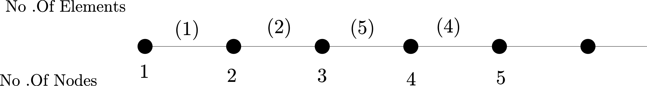
The nodal displacement vector is X c = [x1, y1, θx1, θy1, x2, y2, θx2, θy2].
2.5. Equation of motion for rotating shaft
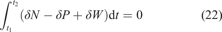
Since the potential and kinetic energies for each element can be presented in a matrix form in terms of its nodal variables, we can write a finite element equation of a rotating shaft using Hamilton’s principle,

3. Model verification and analysis
3.1. Model verification with literature comparison
In this section, the rotor behaviors are investigated using orbit plots, as depicted in Figure 4. The results of the present finite element model are verified and assured through comparison with the results of the low-dimensional model by (El-Sayed and Sayed, 2022). For all cases considered, a dimensionless ratio L/D = 1 is used, where X
j
= x
j
/c, Y
j
= y
j
/c, and S = Comparison of trajectory plots for the journal center between the F.E. model and the model proposed by (El-Sayed and Sayed, 2022). For all conditions, (a), (d), and (g) represents first-order bearing coefficient solution, (b), (e), and (h) represents second-order bearing coefficient solution, and (c), (f), and (i) represents nonlinear solution.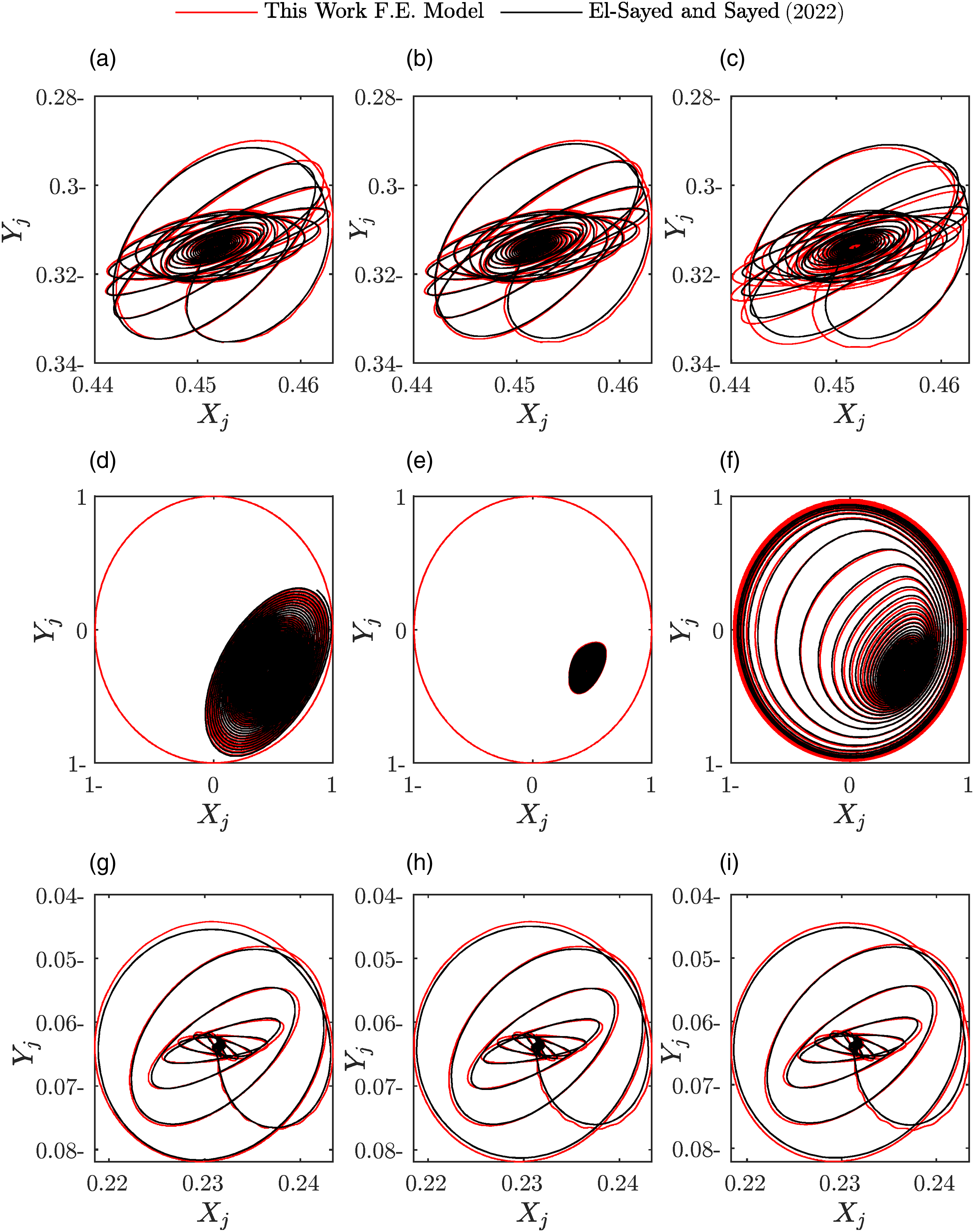
For all the aforementioned methods, three running conditions are considered. In the first case, shown in first row of Figure 4, the rotating speed is below the threshold speed, with a Sommerfeld number of S = 0.148, eccentricity ratio of ɛ = 0.55, and mass
The present model results are compared with those of Tieu and Qiu (1995) in another example, as shown in Figure 5. Three dimensionless masses of Comparison of trajectory plots for the journal center between the F.E model and the model proposed by Tieu and Qiu (1995). For all conditions (a), (c), and (e) represents first-order bearing coefficient solution, (b), (d), and (f) represents nonlinear solution.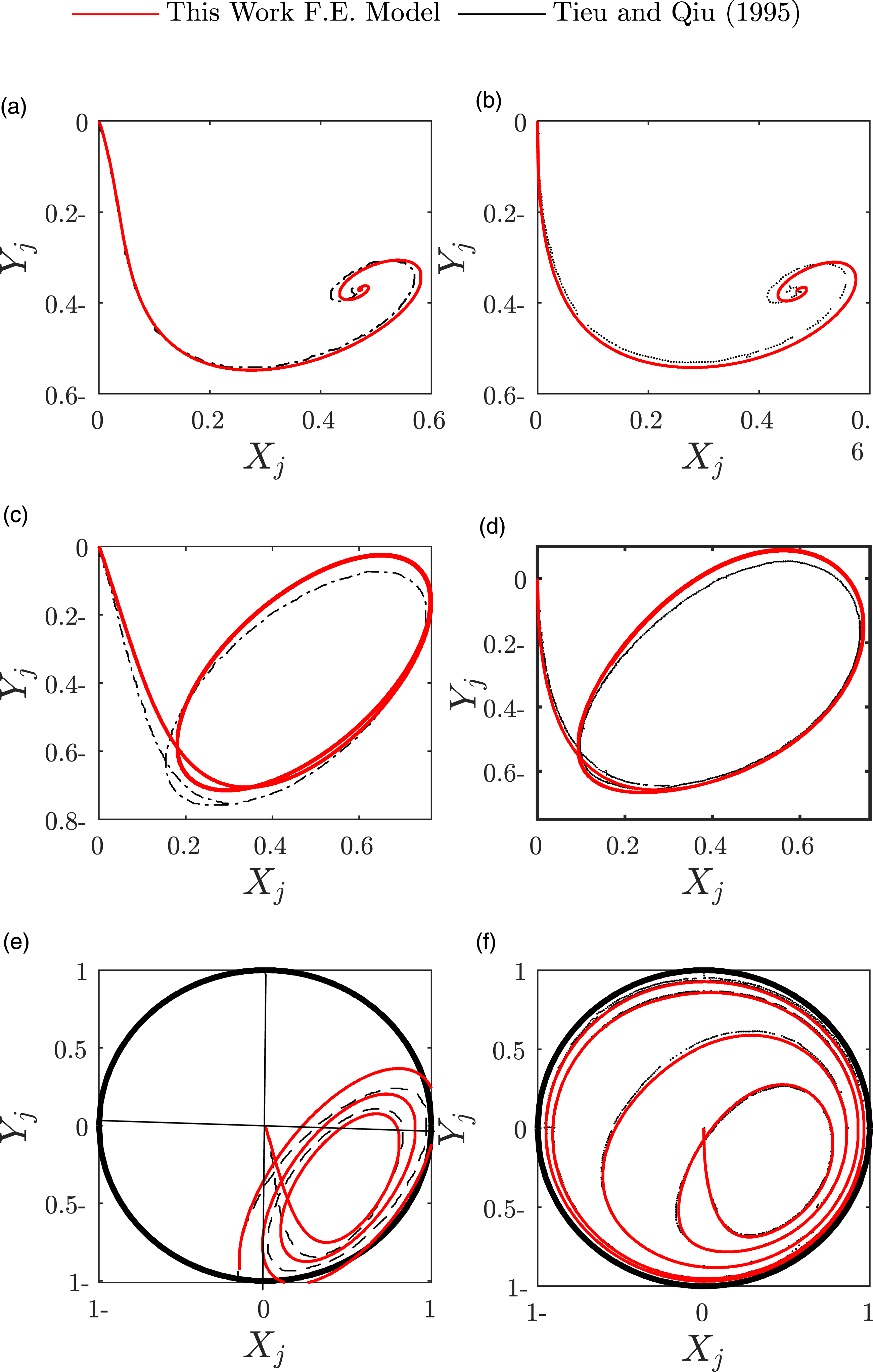
For the first case, which is below the threshold speed, the trajectory reaches the equilibrium point, while the other two cases are above the threshold speed, and the rotor trajectory ends up with a limit cycle in the case of nonlinear analysis. In the case of first-order analysis, the model results in an unstable orbit which grows until it hits the clearance circle. The reference model parameters (K s = 48EI/L3 = 3.68 × 10⁸) are used to represent the model, and the initial conditions of X = Y = 0 are assumed. The present rotor trajectories are in good agreement with those of Tieu and Qiu, demonstrating the validity and accuracy of the present model.
3.2. New results and findings
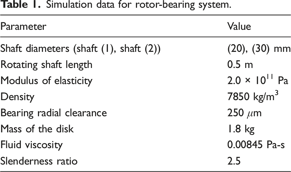
Simulation data for rotor-bearing system.
Here, three different analyses were performed to investigate the behavior of the rotor. The first analysis, marked in blue, employed a linear first-order analysis of the bearing forces. The second analysis, marked in black, relied on the second-order analysis of journal bearing forces. The third analysis, marked in red, was evaluated directly from the Reynolds equation, where the Reynolds equation was solved at each time step to determine the journal bearing forces. Orbits for various speeds lower than the threshold speed are presented in Figures 6(a), (c), and (e). The three analyses provide the same behavior of response as indicated and the corresponding amplitude in a vertical direction are shown in Figure 6 panels (b), (d), and (f). A stable locus was developed at speeds below the threshold speed, and the vibration response decreased over time. Trajectory and vertical displacement time response plots for the center of journal bearing at different operating points (a), (b) 200 rad/sec, (c), (d) 300 rad/sec, and (III) 400 rad/sec as shown in Table 2. Studied points for rotor-bearing orbits and time responses for a shaft diameter of 20 mm.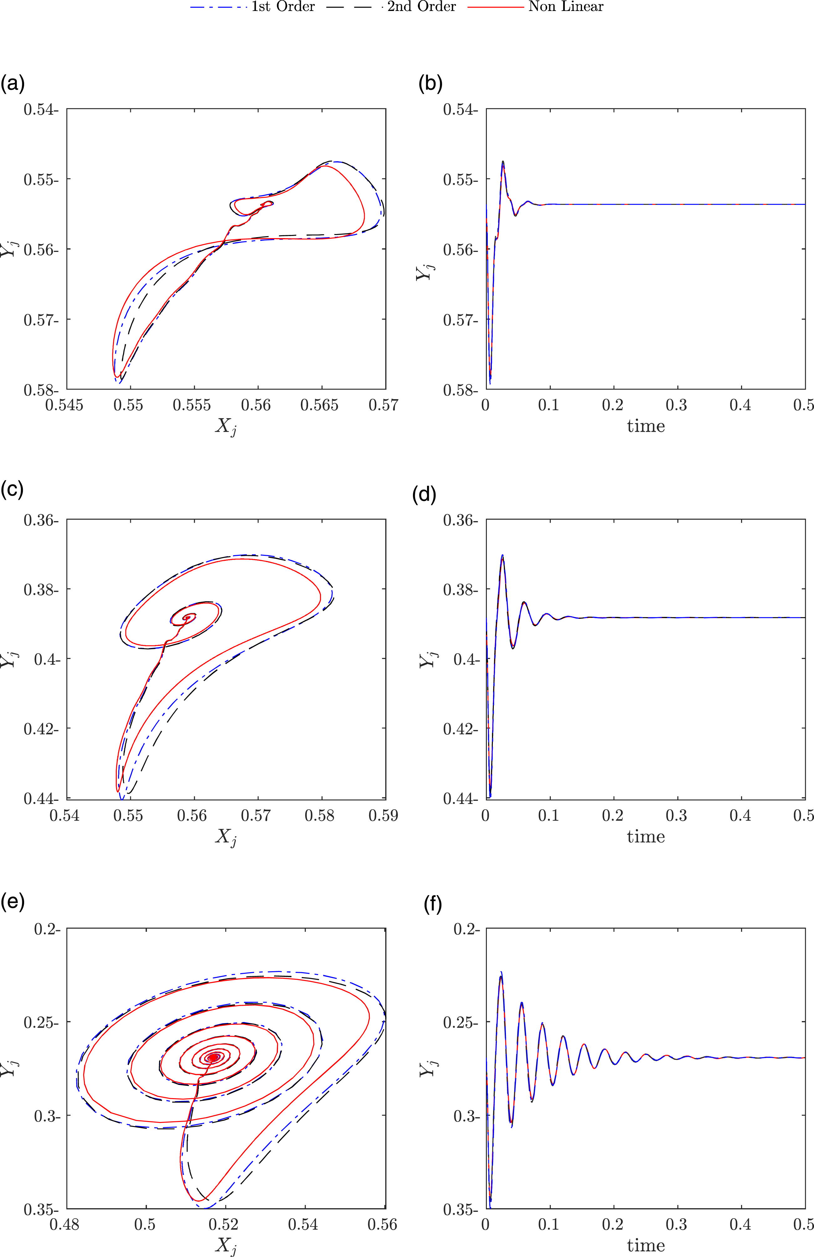
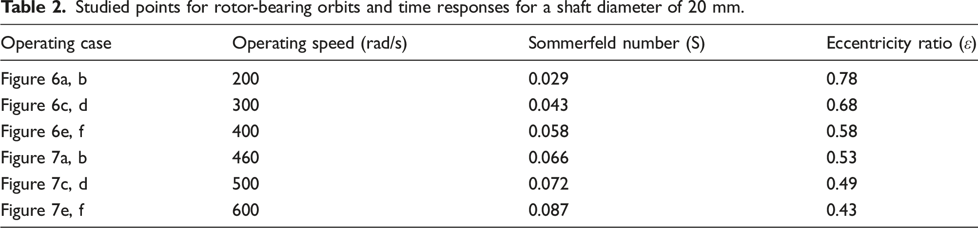
Figure 7(a) illustrates that the journal center continuously increases until it reaches a limit cycle for nonlinear analyses, while it continues to increase in the case of first-order and decrease in the case of second-order analysis orbit until reaching a small limit cycle. The amplitude of vibration increased in the nonlinear analysis compared to the first- and second-order analyses, as shown in Figure 7(b). For Figure 7(c) and (e), both at speeds greater than the threshold speed, the behavior of the rotor for the three analyses demonstrated unstable behavior, and the response continued to grow until the journal hit the bearing clearance circle. The displacement in the vertical direction increased rapidly, as observed in Figure 7(d and f). Trajectory and vertical displacement time response plots for the center of journal bearing at different operating points (a), (b) 460 rad/sec, (c), (d) 500 rad/sec, and (e), (f) 600 rad/sec.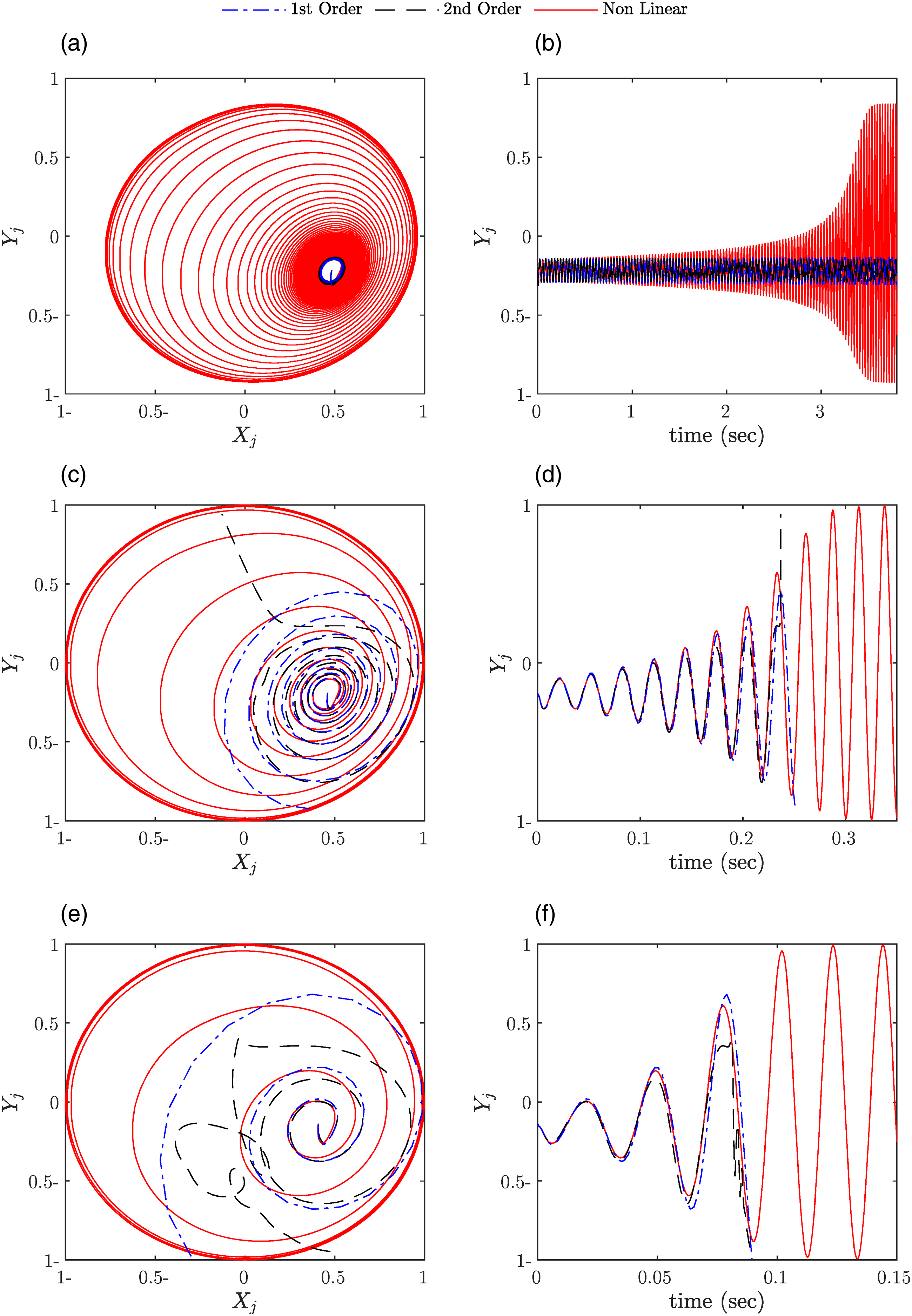
3.2.1. Effect of changing shaft diameter (d = 30 mm)
This section investigates the effect of changing the rotating shaft diameter using several trajectories for different Sommerfeld numbers, eccentricity, and rotating speed parameters. The results of all analyses, including the first- and second-order bearing coefficients and the nonlinear force analysis, exhibited similarity for trajectory plots below the specified threshold, as presented in Figure 8(a)–(f). Table 3 Trajectory plots for the center of journal bearing at different operating points (i) 200 rad/sec, (II) 300 rad/sec, and (III) 400 rad/sec as shown in Table 3. For all cases (a), (c), and (e) present orbit plot for studied case, and (b), (d), and (f) time response of vertical displacement. Studied points for rotor-bearing orbits and time responses for a shaft diameter of 30 mm.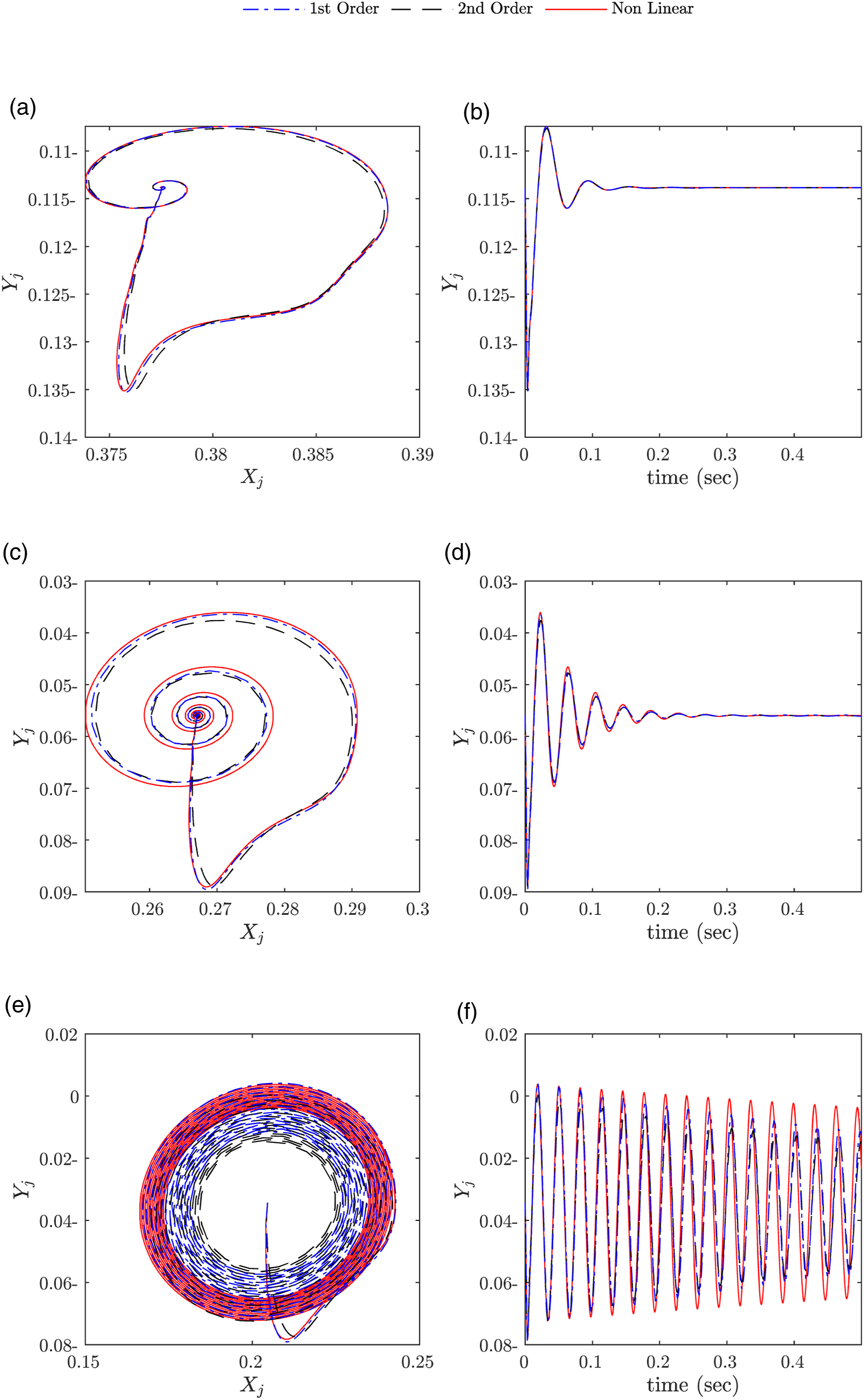

For Figure 9(a), the rotor speed was almost near the threshold speed. The orbit in the first-order analysis decreased with increasing run time, while the second-order analysis showed a limit cycle with stable steady-state conditions. Furthermore, the nonlinear analysis orbit grew with time to reach a limit cycle. For Figure 9(c) and (e), the rotor speed was above the threshold speed. The second-order analysis grew until it reached a limit cycle, while the nonlinear analysis grew continuously until it was bounded by the bearing clearance cycle. In contrast, the first-order analysis showed the response growing until the journal hit the bearing clearance circle. Trajectory plots for the center of journal bearing at different operating points (IV) 405.5 rad/sec, (V) 500 rad/sec, and (VI) 600 rad/sec, as shown in Table 3. For all cases (a), (c), and (e) present orbit plot for studied case, and (b), (d), and (f) time response of vertical displacement.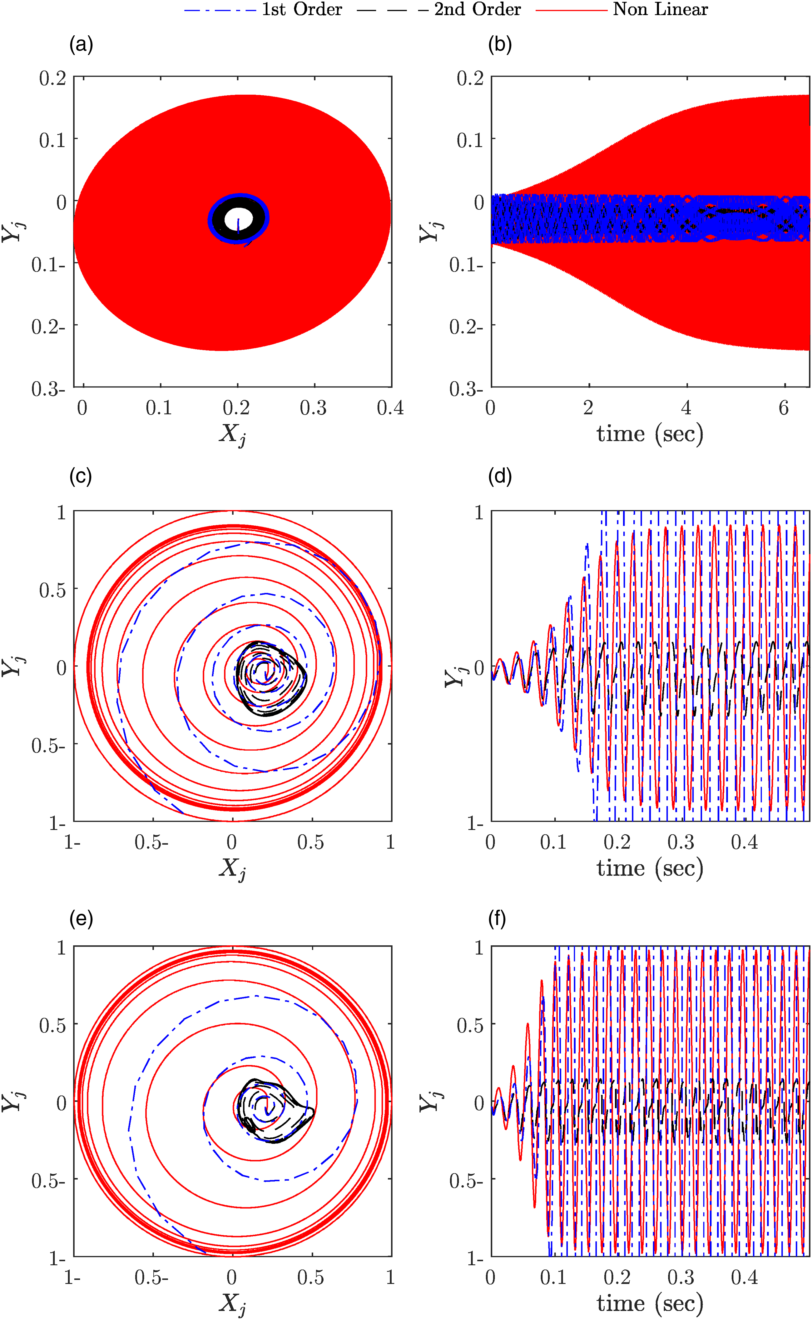
Directly comparing the trajectories of the first-order, second-order, and nonlinear analysis, it is evident that the predicted results agree quite well at low rotational speeds, as shown in Figure 8(a)–(f). However, the orbits start to deviate more as the rotational speed is increased. Furthermore, at high speeds, even the qualitative pattern in the derived trajectories differs, as observed in Figure 9(c)–(f). After comparing the results of two different shaft diameters, it was observed that the threshold speed for the 20 mm shaft diameter is greater than that for the 30 mm shaft diameter. Additionally, in the first case, a second-order analysis revealed unstable behavior and an increase in orbit size, which quickly exceeded the clearance circle’s limits at speeds greater than the threshold speed. In contrast, the second case showed an increase in the responses and the orbits reached a small limit cycle.
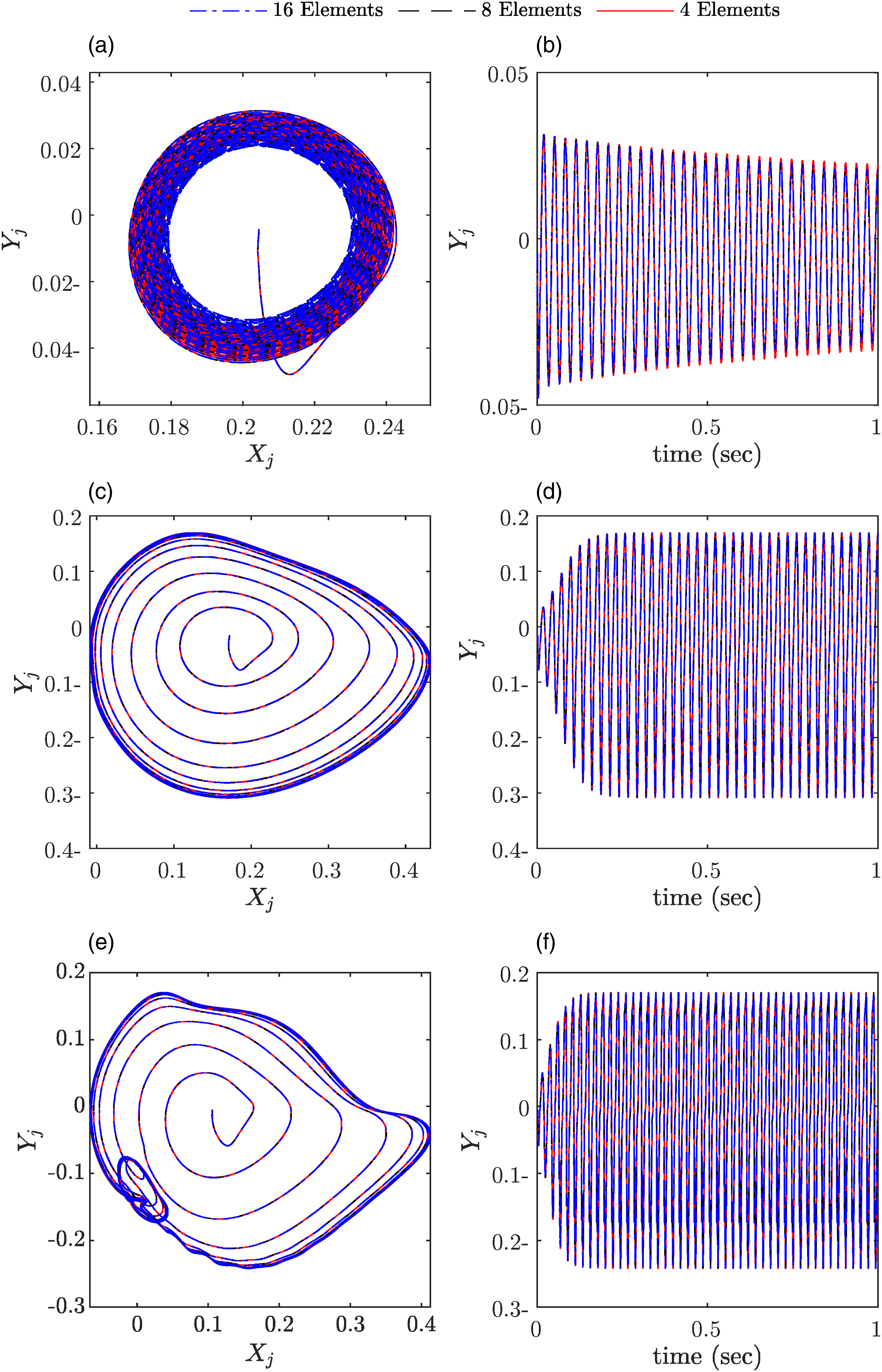
3.2.2. Effect of changing number of elements
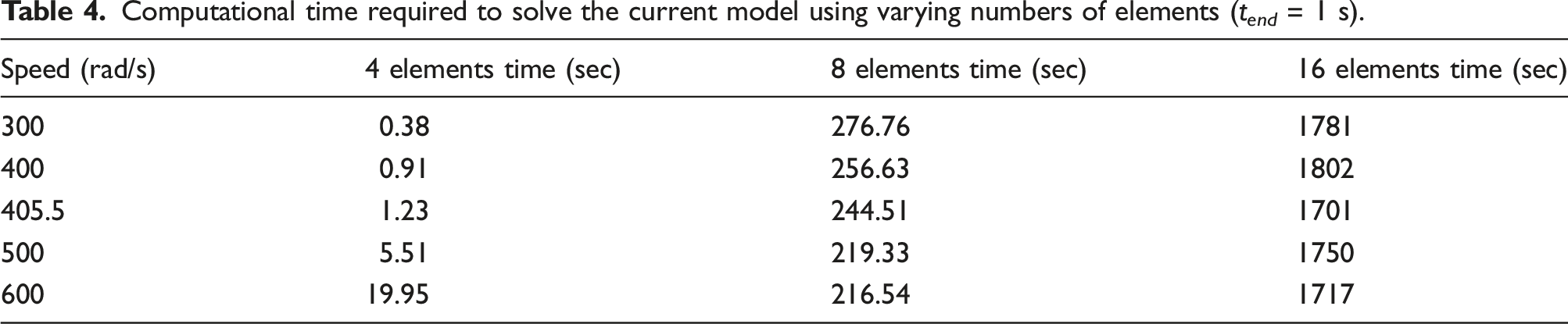
In this section, the influence of the number of elements on the orbits and dynamic response of the rotor bearing is investigated across various rotational speeds. The analysis focuses on a shaft diameter of 30 mm. The system equations of motion are solved, and nonlinear forces are evaluated using second-order dynamic coefficients to generate the trajectory plot and time response plot, which are presented in Figures 10 and 11. The results demonstrate consistent responses and orbits across different numbers of elements and rotational speeds. Additionally, Table 4 presents the computational time required to obtain the orbits and response graphs using varying numbers of elements, highlighting that increasing the element count leads to longer computational times. Trajectory plots and time response of vertical displacement for the center of journal for different number of elements with operating points ((a), (b) 300 rad/sec) and (c),(d) 400 rad/sec, as indicated in Table 4. Trajectory plots and time responses of vertical displacement for the center of the journal, with varying numbers of elements at different operating points. Specifically, the operating points (a), (b), (c), (d), and (e), and (f) correspond to rotational speeds of 405.5 rad/sec, 500 rad/sec, and 600 rad/sec, respectively, as detailed in Table 4. Computational time required to solve the current model using varying numbers of elements (t
end
= 1 s).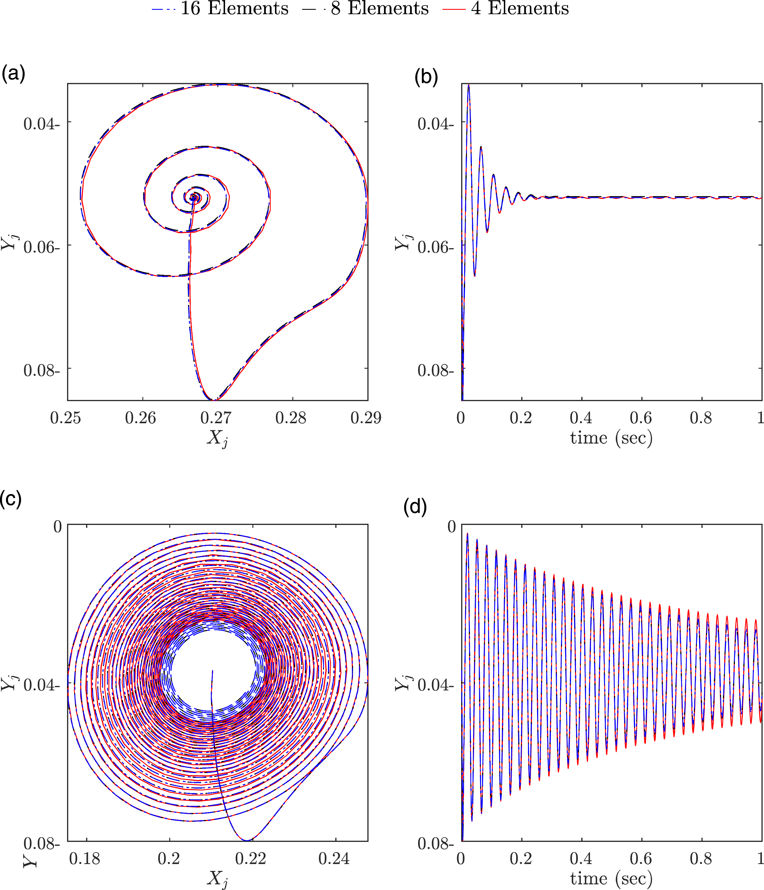
3.2.3. Bifurcation diagrams
This section presents bifurcation diagrams for the stability analysis of a flexible rotor supported by symmetric fluid film bearings. Bifurcation diagrams allow for a straightforward investigation of how various rotor operational conditions and characteristics, such as rotational speed, different shaft diameters, and rotor unbalance, affect the stability of the rotor-bearing system. To generate bifurcation plots, the rotational speed is incrementally changed with a constant step of 25 rad/s, and the resulting values at the end of each step are utilized as the initial value for the subsequent speed value.
The studied cases are subjected to unbalance forces exerted on the rotor, which affect the dynamic performance of the rotor-bearing system. The magnitude of the unbalance mass times the eccentric distance is equal to m × e = 10−4 kg.m for two different shaft diameters. Figure 12 presents bifurcation and three-dimensional spectrum diagrams for two different shaft diameters. The range of rotational speeds investigated for the 20 mm shaft diameter is 50–425 rad/s, while for the 30 mm shaft diameter, it is 200–800 rad/s. The bifurcation analysis and the waterfall diagrams reveal that the orbits corresponding to the smaller shaft diameter exhibit divergence beyond 425 rad/s. Vertical displacement bifurcation and 3D waterfall plot for different shaft diameters at L/D = 2.5. (a), (b), (d), (e) show the bifurcation diagrams for shaft diameters of 20 and 30 mm, respectively. (c), (f) show the corresponding 3D waterfall plots.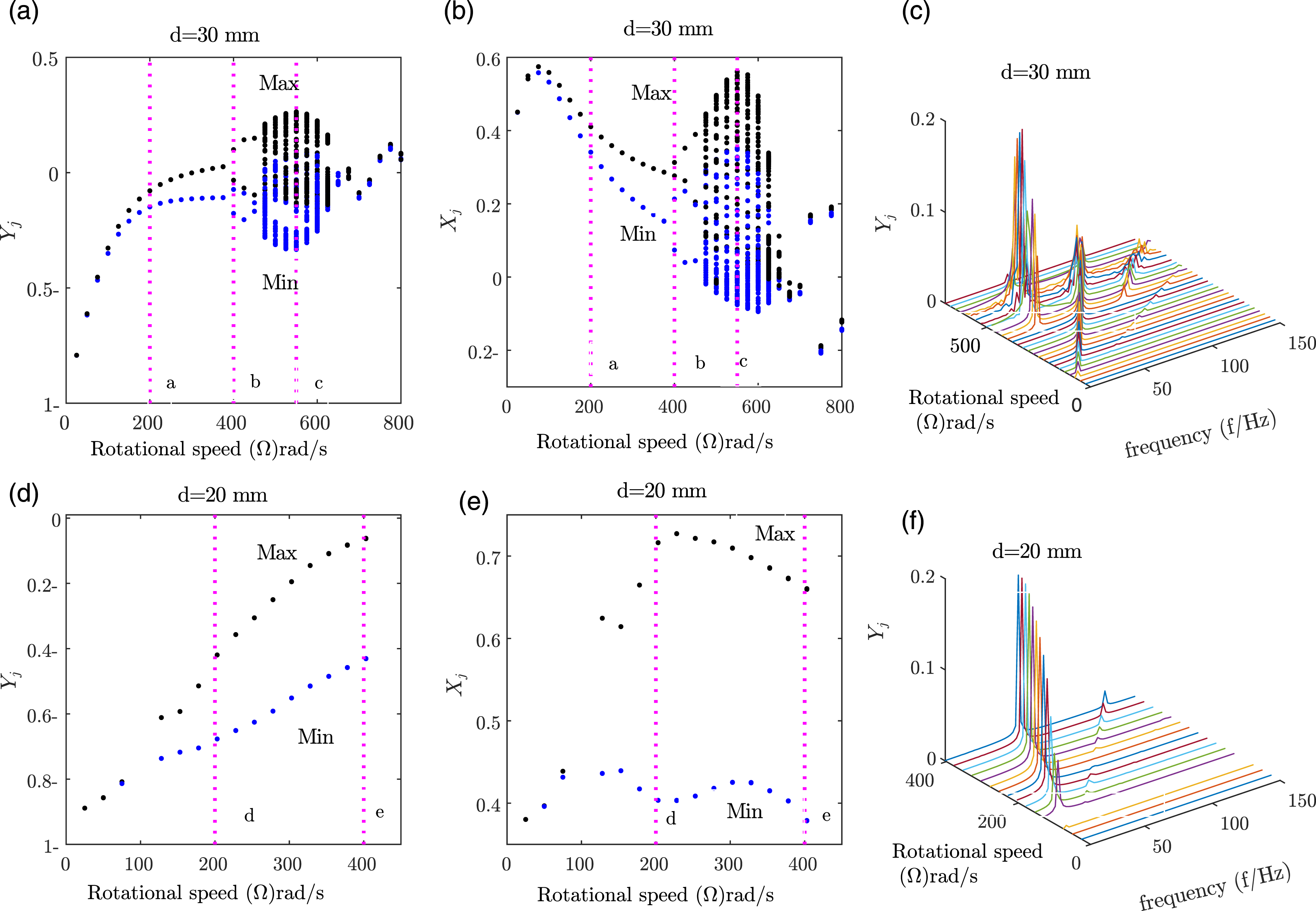
The bifurcation diagram results indicate that the rotor steady-state behavior remains period one in a condition at a speed lower than 400 rad/s. There is only the essential frequency present in the waterfall diagrams, which identifies it as the synchronous response. However, as the rotational speed gradually increases above 400 rad/s, a period-doubling bifurcation occurs in the rotor-bearing system. Moreover, the fundamental frequency and the one-half subharmonic frequency begin to appear in the waterfall diagrams. This behavior implies the existence of an oil whirl in the rotor system, namely, half frequency whirl.
Figure 13 presents the shaft orbit diagrams for different velocities (200, 400, and 550 rad/s) at a shaft diameter of 30 mm. The orbit trajectory for a shaft diameter of 20 mm is presented in Figure 13(d) and (e). At low rotational speeds, selected cases are plotted, as shown in Figure 13 (a), (b), (d), and (e) for the two different shaft diameters. The orbits demonstrate that the rotor-bearing system exhibits stable behavior. However, as the rotational speed increases, quasi-periodic response is observed as shown in Figure 13(c). In the case of a shaft diameter of 20 mm, the rotor-bearing system diverges at high speeds due to the system’s unstable behavior. Trajectory plots for various cases from Figure 12. (a), (b), and (c) show sample trajectories at different velocities when the shaft diameter d is 30 mm. (d) and (e) show trajectory plots when the shaft diameter d is reduced to 20 mm.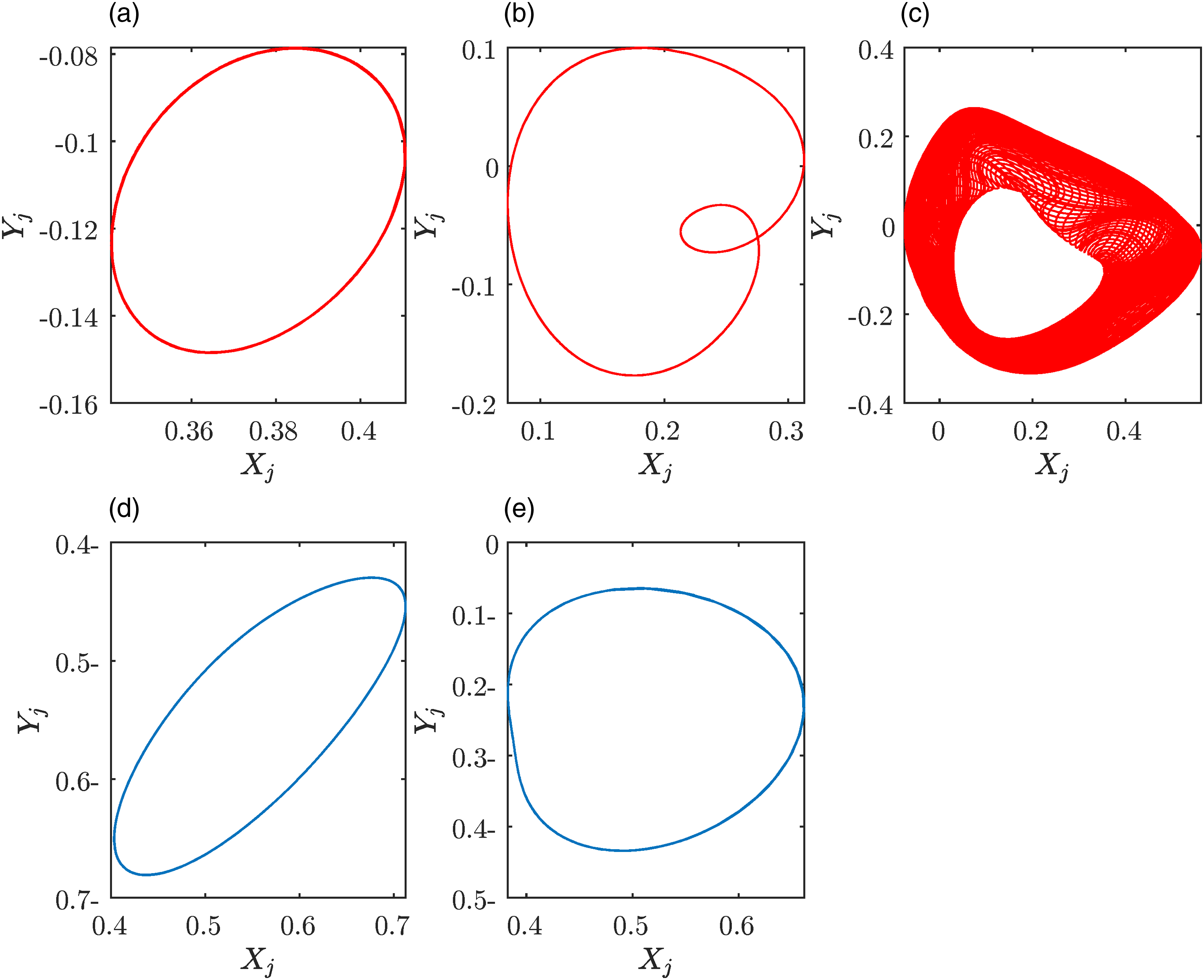
3.2.4. Three-dimensional spectrum diagrams
Figure 12 presents the frequency content of the journal response at different rotational speeds, which can be studied through Fourier analysis. The FFT spectrum data were collected for each speed and plotted accordingly using a MATLAB code. As referred to above, the plots show how the rotational speed Ω changes throughout a range, and how synchronous changes in the rotor-dynamic behavior are studied. A typical tool in rotor dynamics is the three-dimensional spectrum diagrams of the journal vibrational signal in the present frequency domain, which is used to show the change in dynamic characteristics with varying rotational speeds of shaft diameters of 20 and 30 mm, respectively.
The flexible rotor’s waterfall plots illustrate the following characteristics: (1) The synchronous frequency component is seen to extend from the lower rotational speeds to the higher spin speeds. When the speed of the rotor is less than 400 rad/s, there is small-amplitude synchronous vibration, as shown in Figure 12(c, f). (2) When the rotor is spinning at a high speed above 400 rad/s, the sub-synchronous whirl amplitude grows, and oil whirl, as well as a part of synchronous vibration, appears, as noted in Figure 13(c).
4. Conclusions
In this study, a finite element code was developed to analyze the behavior of a flexible rotor supported by symmetrical hydrodynamic bearing systems. The rotor system was formulated using Euler-Bernoulli beam theory in the finite element analysis. The first- and second-order dynamic bearing coefficients were evaluated and used in the analysis to determine the rotor trajectories by evaluating the bearing forces. The obtained results were compared with trajectories obtained using direct solutions of Reynolds analysis. The influence of shaft diameter and rotational speed on the rotor-bearing system was also investigated. The main conclusions derived from this study are as follows: • The results obtained from the finite element model align with the results from the low-dimensional model presented by (El-Sayed and Sayed, 2022; Tieu and Qiu, 1995). • The shaft diameter had minimal impact on the amplitude range in all three analyzed cases: first order, second order, and nonlinear analysis. • The analysis based on the 2nd order approximation of bearing stiffness and damping coefficients yields similar results to the analysis based on the direct evaluation of the nonlinear force from the Reynolds equation. The orbit plots and rotor responses are significantly influenced by changes in rotational speed. • Bifurcation diagrams exhibit synchronous responses at low rotational speeds, while increasing the rotor speed leads to period-doubling bifurcation. Furthermore, changes in shaft diameters have little effect on the bifurcation diagrams. • Waterfall diagrams show distinct behavior at low rotor speeds, but as the rotor speed increases, large amplitude peaks appear, indicating synchronous vibration oil whirl.
The presented finite element model can be utilized to predict the dynamic characteristics and stability diagrams of rotor-bearing systems. Experimental validation of the findings in future research is recommended.
Footnotes
Declaration of Conflicting Interests
The author(s) declared no potential conflicts of interest with respect to the research, authorship, and/or publication of this article.
Funding
The author(s) received no financial support for the research, authorship, and/or publication of this article.
Data Availability Statement
The datasets generated during and/or analyzed during the current study are available from the corresponding author on reasonable request.