
Abstract
In this article, a high-speed forming press using electromagnetic pulse force is designed with the finite element analysis. The punch of the press is fixed to an aluminum plate driven by electromagnetic pulse force. The force is the repulsive force between the aluminum plate and the coil. The coil is supplied with a high-voltage AC current impulse from the capacitor, and then the magnetized aluminum plate moves upward at high speed to perform the pressing. For the analysis of the pressing, the coupled analysis of electromagnetic field and rigid-body dynamics of the aluminum plate is performed with a commercial finite element software, ANSYS, and the rigid-body dynamics theory. A simple upsetting test is performed with the high-speed press.
Introduction
High-speed forming is widely investigated to overcome the lower formability of high strength material. 1 In high-speed forming, the workpiece can be accelerated to high speed of up to several hundred meter per second. According to Psyk et al., 2 the mechanical properties and the formability of the workpiece material can be improved at the high strain rates. Electromagnetic forming (EMF) is one of high-speed forming that uses induced electromagnetic forces by a transient high-voltage AC current. In recent years, interests in EMF have been growing in the field of high-speed forming since EMF offers several advantages over the conventional forming method. The papers related to EMF and magnetic pulse welding (MPW) are 79% among the papers presented in the high-speed forming conference, ICHSF2012. 1
In general, the punch which is essential for the conventional forming is not required in EMF process because the EMF force is applied to the workpiece directly. However, some high-speed forming technologies have been developed for the forming processes that require the punch, such as high-speed blanking and stamping with a small radius.3–5 Vohnout 3 proposed combined deep drawing and electromagnetic calibration to form a door inner and a hood part with complex geometries. The geometrical details are calibrated electromagnetically using the coil integrated in the punch. Grünbaum et al. 4 investigated the quality of blanked parts at the high-speed blanking process. Shim et al. 5 developed electro-mechanical coupled finite element (FE) model for EMF of thin aluminum plate using the punch.
In this article, a high-speed forming press using electromagnetic pulse force is designed with the FE analysis. The punch of the press is fixed to an aluminum plate driven by electromagnetic pulse force. The force is the repulsive force between the aluminum plate and the coil. When the coil is discharged with a high-voltage AC current impulse from the capacitor, the magnetized aluminum plate forced to move upward at high speed. The high-speed forming process is then conducted.
The forming process is limited to the kinematic energy of the aluminum plate. The kinematic energy is determined with the mass and velocity of the plate. To evaluate the velocity of the plate and the analysis of the pressing, the coupled analysis of electromagnetic field and rigid-body dynamic of the aluminum plate is performed with a commercial FE software, ANSYS, 6 and the rigid-body dynamics theory. 7 A simple upsetting test is performed with the high-speed press. The test result demonstrates the possibility of application of the high-speed forming process.
High-speed press using electromagnetic pulse force
Press system
As shown in Figure 1, the high-speed press system consists of an aluminum plate with the punch, a steel fixture, a spacer, an upper die, and a coil. When the stored charging energy of the magnetic power source is discharged to the coil, electromagnetic force is generated between the aluminum plate and the coil. Then the aluminum plate moves at high speed by this electromagnetic pulse force.

Schematic diagram.
The coil shape is one of important factors for achieving successful forming because the magnitude and distribution of the electromagnetic force on the aluminum plate can be changed depending on the shape of the coil. In this study, the bar-type coil is employed for getting high electromagnetic force during the forming process as shown Figure 2. The bar-type coil has high current density than others shape, thus this coil can generate the high electromagnetic field between the coil and the aluminum plate instantaneously. 8 In addition, the bar-type coil has the high strength that is able to endure the reaction force during the forming process.

Bar-type coil.
Electromagnetic pulse power source
As shown in Figure 3, electromagnetic pulse forming system includes a magnetic pulse power source which consists of capacitor banks and high-speed press. Specifications of the electromagnetic pulse forming system are shown in Table 1. System capacitance is 840 μF and charging voltages can be varied from 1 to 10 kV, resulting in charging energy from 0.42 to 42 kJ. In addition, Rogowski coil is installed around the magnetic pulse power source and the coil in order to observe a discharge current and its waveform.
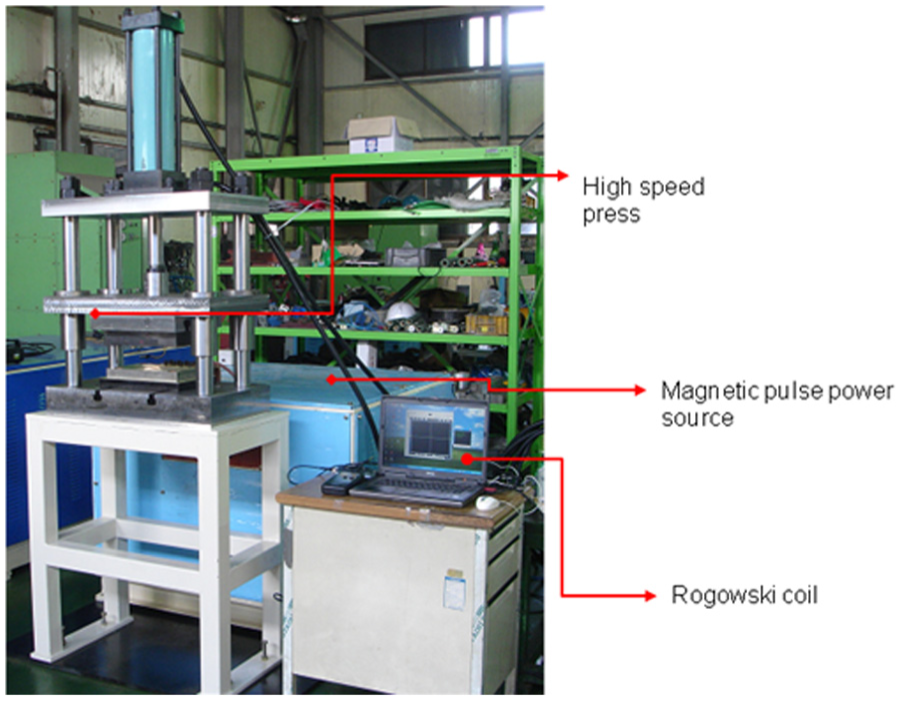
Electromagnetic forming system.
Specification of electromagnetic pulse forming system.

Coupled analysis
Electromagnetic field analysis
Using ANSYS, 6 the electromagnetic field analysis is performed to obtain electromagnetic force. For simplification of modeling, the coil and the aluminum plate are assumed to be axisymmetric. Figure 4 shows the FE model for the analysis. FE model is constructed using the two-dimensional (2D) eight-node magnetic solid element. Since EMF system is assumed to be equivalent RLC circuit, 2 the electric circuit is evaluated. In the model, the capacitance is 840 μF and the inductance is 0.4 μH. The charged energy is 10.5 and 15.12 kJ when the initial voltage is 5 and 6 kV, respectively. The magnetic fields and corresponding electromagnetic force are analyzed with the obtained circuit on the coil. Table 2 shows the material properties and the dimensions of the coil and the plate.

FE model for the electromagnetic analysis.
Material properties and the dimensions of the FE model.

FE: finite element.
Rigid-body dynamic analysis
The motion of the aluminum plate assumed to be a particle with the plate weight can be evaluated with rigid-body dynamics
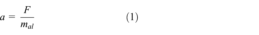
where a is the acceleration of the plate, mal is the mass of the plate, and the force, F, is the z-directional total force obtained from the electromagnetic analysis. Adams−Bashforth’s two-step method 7 is applied to solve equation (1). The z-directional displacement of the aluminum plate can be calculated with the velocity as shown below

where ai and ai + 1 are the acceleration of the plate at ith and (i + 1)th step; vi and vi + 1 are the velocity of the plate at ith and (i + 1)th step; and Δ is the time increment between ith and (i + 1)th step.
Coupled analysis
According to Risch, 9 an electromagnetic force during an EMF process is observed as a continuously decreasing force because of an increasing gap volume due to deformation of workpiece. In order to obtain the electromagnetic force accurately, the effect of the increasing gap volume between the coil and the plate needs to be considered. Thus, the electromagnetic analysis and the dynamic analysis are coupled. To solve the coupled fields, the electromagnetic force is obtained from the electromagnetic analysis. The force is applied to the aluminum plate and the displacement of the plate can be calculated with the dynamics. The FE model of the plate is changed with the new position and the electromagnetic analysis is repeated. Figure 5 shows the coupled analysis method.

The coupled analysis method.
Analysis results
Electromagnetic force
Electromagnetic force is obtained with various conditions. The effects of initial voltage and the mass of the plate on the force are considered since the initial voltage is related to the electromagnetic charging energy and the mass of the plate determines the acceleration of the plate. Figure 6 shows the electromagnetic force applied to the aluminum plate. The force varied with the initial voltage and the mass of the plate. First peak force increased with the high initial voltage of 6 kV and the lighter plate, because the displacement of the plate increases as the mass of the plate decreases. Figure 7 shows the distribution of the electromagnetic force at the first peak with 6 kV and 2.0 kg. The force is generated at the small region closed to the coil.

The electromagnetic force with various conditions.

The distributed electromagnetic force on the plate.
Forming speed
Because the punch is fixed on the aluminum plate, forming speed is same as the velocity of the aluminum plate. Figure 8 shows the forming speed with various conditions. With the initial voltage of 6 kV and 0.5 kg plate, forming speed of 4.3 m/s can be obtained. On the design of the press, the mass of the aluminum plate must be considered to obtain the certain velocity. In addition, the capacity of the magnetic pulse power source is important for the forming speed since EMF force increases as the initial voltage increases as shown in section “Electromagnetic force.” The forming speed and the kinematic energy of the plate with various conditions are shown in Table 3. The forming speed depends on the weight of the aluminum plate and the initial voltage. More speed of the aluminum plate is expected with the lighter plate and higher initial voltage.

Forming speed of the press.
Forming speed and kinematic energy of the moving aluminum plate.

Simple upset test
Simple upsetting experiments are conducted to verify the high-speed forming press designed with the coupled analysis. The bar-type coil and a 4.776 kg aluminum plate are used in the simple upsetting experiments. In the experiments, the coil with an epoxy molding is used for insulation. The billet material is A6061-O and the diameter of a billet is 15 mm. The ratio of the height and the diameter is set to be 1. The pictures are taken by the high-speed motion capture camera, FASTCAM-SA4 500K-C1. Figure 9 shows sequence of the upsetting experiment. Figure 9(a) is the picture before upsetting, Figure 9(b) is that of the beginning discharge, and Figure 9(c)–(e) is that after 5/3600, 10/3600, and 15/3600 (s), respectively. The billet is not shown in Figure 9 because that was placed in the die. The aluminum plate starts to move with high speed after discharging and the speed of the plate is calculated by the image analysis. The results of the upsetting are shown in Table 4. The aluminum plate speed is much higher than those of the analysis because the higher magnetic force is generated at the edge and the corner of the rectangle shape coil than the smooth shape. 10 For the design of the press, the accurate analysis with a real shape coil is required.
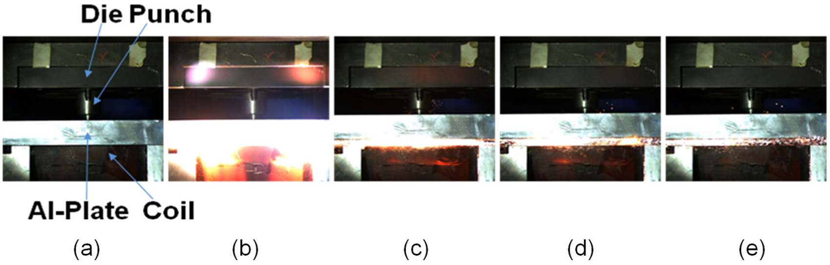
Upsetting experiments with the high-speed press (the initial capacitor voltage is 5(kV)): (a) before upsetting; (b) beginning of discharge; (c) 5/3600 s after discharge; (d) 10/3600 s after discharge; (e) 15/3600 s after discharge.
Results of the upsetting experiments.

The plastic dissipated energy can be calculated using the forged height by neglecting elastic deforming energy and the dissipated energy due to the friction

where σ0 is the flow stress, h0 and h1 are initial and forged height of the billet, and vol is the volume of the billet. The average flow stress of the billet is about 150 MPa. 11 From the dissipated energy, an approximate calculated speed of the plate can be obtained as shown in Table 4. Those are a good agreement with the measured values.
Conclusion
In this article, the high-speed forming press using the electromagnetic pulse force is designed with the coupled analysis. Some conclusions are obtained as below. The induced electromagnetic force is distributed on the region closed to the coil. The forming speed depends on the weight of the aluminum plate. More speed of the aluminum plate is expected with the lighter plate and higher initial capacitor voltage. The high magnetic force is generated with the rectangle shape coil in the experiment. From the upsetting experiments, the approximate speed is calculated with the forged height.
Footnotes
Academic Editor: Soheil Salahshour
Declaration of conflicting interests
The author(s) declared no potential conflicts of interest with respect to the research, authorship, and/or publication of this article.
Funding
The author(s) disclosed receipt of the following financial support for the research, authorship, and/or publication of this article: This work was supported by Ministry of Trade, Industry & Energy (10062301), Korea.