
Abstract
The frictional multiplier of steam-water two-phase flow in four-head internally ribbed tubes was experimentally investigated under two test conditions—adiabatic and heated. The internally ribbed tube has the following dimensions: outside diameter 28.6 mm, wall thickness 5.8 mm, and hydraulic diameter 15.24 mm. The test tube, 2000 mm in length, was vertically installed and uniformly heated electrically. A wide range of experimental parameters were considered. The pressure range was 9–31 MPa, mass flux range was 600–1800 kg/(m2 s), and steam quality range was 0–1 in subcritical pressure region. In this study, the effects of pressure, mass flux, and steam quality on the frictional multiplier were analyzed. The corresponding empirical correlations were presented. The variation in pressure drop between the adiabatic tube and heated tube was determined. The experimental results demonstrated that the characteristics of the frictional pressure drop in the internally ribbed tube under heated and adiabatic conditions are dissimilar. The two-phase frictional multiplier in the heated tube is higher than that in the adiabatic tube. With the decrease in the pressure or increase in the steam quality, the two-phase frictional multiplier increases gradually. However, the single-phase frictional factor in the heated tube is smaller than that in the adiabatic tube in the subcritical and supercritical pressure region.
Introduction
The performance and efficiency of a thermal system can be significantly enhanced if the dimensions of the heat exchangers are reduced according to “optimum” heat transfer enhancement techniques for fixed heat duty. Because the ribbed channel can be used as a passive heat transfer enhancement tool, a series of ribbed channels are generally utilized in industrial devices such as the heat exchangers of chemical engineering systems, refrigerators, and micro-coolers of electronic systems.1–6 Various types of ribbed tubes are widely used in boilers to delay the departure from nucleate boiling (DNB).7,8 The internally ribbed tube is widely used in the water walls of modern supercritical boilers such as supercritical circulating fluidized bed (CFB) boilers and supercritical pressure W-shape flame boilers. The turbulence in the proximity of the tube wall surface is enhanced to reduce the thermal boundary layer thickness by a chaotic mixing of fluid in the internally ribbed tube, which has been reviewed by Mohsen et al. 9 and Kareem et al.; 10 in this manner, the heat transfer is enhanced. It is evident that frictional pressure drop in internally ribbed tubes is significantly higher than that in smooth tubes.
Accurate predictions of frictional pressure drop of single-phase and two-phase flows are crucial for the effective design of thermal-exchange equipment for industrial purposes because the pressure drop determines the power input in a fixed-flow system. In addition, the pressure drop also determines the mass flux, flow distribution, and critical heat transfer (CHF) in a fixed pressure drop system. Although considerable research has been conducted, such as those by Bergles, 11 Guo et al., 12 Srinivasan et al., 13 Zdaniuk et al., 8 and Taklifi et al., 14 and numerous empirical correlations have been proposed in the past decades, these study results are ineffective for achieving the purpose. For example, there is negligible information on certain effects of flow pattern and condition parameters on frictional pressure drop of steam-water two-phase flow. With the development of enhanced heat transfer technology, the prediction of two-phase flow frictional pressure drop in ribbed flow channel has become highly critical. Compared with the smooth channel, heat transfer is higher in the ribbed channel; this is accompanied by a higher two-phase flow frictional pressure drop. For a ribbed tube, numerous factors such as tube diameter, rib parameters, inner surface configuration, rib structure, and flow pattern affect the prediction of two-phase flow frictional pressure drop. Over the past years, predictions of two-phase frictional pressure drop in micro-fin channels15–17 and small diameter tubes 18 have been proposed. A few investigations have been conducted on the internally ribbed tubes used in large capacity boilers. Chen et al., 19 Cheng and Chen, 20 and Yang et al. 4 reported the flow boiling and steam-water two-phase frictional pressure drop in an internally ribbed tube. Kolar 21 experimentally investigated the frictional pressure drop of triangular internally ribbed tube and determined that the two-phase frictional pressure drop is in direct proportion to the numerical value of (e/d)0.63, where e is the rib height and d is the equivalent inside diameter of the tube. Ackerman 22 determined that the frictional pressure drop in the adiabatic ribbed tube is 25% higher than that in the smooth tube. A few research studies23–26 have also demonstrated that the structure of the internally ribbed tube has a significant impact on the frictional pressure drop.
The frictional pressure drop correlations of internally ribbed tubes vary among the diverse rib types. Moreover, a number of these correlations were developed under adiabatic conditions, which differ from actual industrial operating conditions. Therefore, it is necessary to further enrich the corresponding database of pressure drop of two-phase flow within ribbed tubes. In this study, the frictional pressure drop characteristics of steam-water two-phase flow are studied under heated and adiabatic conditions. The system parameters taken into consideration in this study adequately cover the range of the operational parameters of supercritical pressure boiler. The results are likely to provide a set of meaningful references for the design of large capacity heat exchanger.
Experimental setup and method
The experiments were carried out on a high-pressure steam-water two-phase flow test loop capable of attaining pressures of up to 40 MPa at Xi’an Jiaotong University. The test loop is suitable for undertaking experimental research on two-phase flows, single-phase flows, and heat transfer in large steam boilers, nuclear reactors, and heat exchangers. The schematic diagram of the test loop is shown in Figure 1. The test section was a stainless steel tube, which was seamless, cold drawn, and annealed. The experimental system incorporated a series of stainless steel tubes, which together were used as a resistance heater and through which the water flowed. With the resistance heater, the local heat input was determined, and a point heat transfer coefficient could be calculated. Feed water was boosted from the tank by a high-pressure plunger pump and heated by a regenerative heat exchanger and main pre-heater to obtain the required test parameters. Fluids from the test section flowed through the regenerator and condenser and then returned to the tank. The bypass was used to regulate mass, velocities, and pressures in the experiment. The test section and main pre-heater were directly heated by alternating current, with these modules themselves functioning as resistance elements. The heated tubes were enclosed with insulation. In this experiment, the overall heated capacity was 840 kW, of which 180 kW was used for heating the test section. Two electrical terminal bars, which were constructed from copper plate, were drilled and reamed to fit the tube dimension and finally soldered in place.
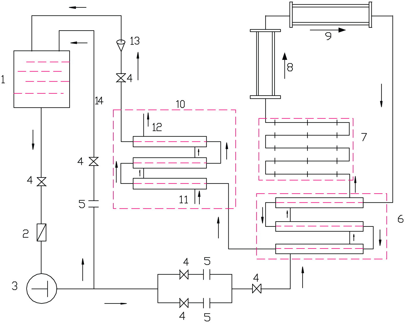
Schematic diagram of the test loop.
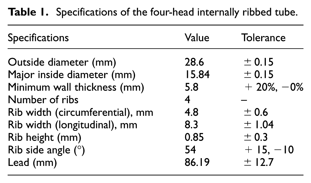
The test tube was a 28.6 mm × 5.8 mm four-rib internally ribbed tube of hydraulic diameter 15.24 mm. The rib was in the form of a helix on the inner surface. Specifications of the test tube are presented in Table 1. The heated length was 2000 mm, measured between the terminal bars. The outer wall temperature of the heated test tube was measured by 96 thermocouples of Φ3 mm NiCr–NiSi (precision of 0.4 K) connected at 14 cross sections along the length of the test section to identify variations in the outer tube wall temperature. These thermocouples were calibrated in a water thermostat system before being used. The adiabatic test section was 2000 mm in length. The electrical heating power was defined as the product of the effective values of the voltage and current.
Specifications of the four-head internally ribbed tube.
Figures 2 and 3 illustrate the structures of the test tubes of the heated test section and adiabatic test section, respectively. The fluid pressure of the test section was measured by the Rosemount 3051 capacitance-type pressure transmitter. ST3000/S900 differential pressure transducers were used to measure the pressure drop of the test section. Furthermore, the measuring accuracy of the differential pressure transducers was 0.25%. These pressure transducers were calibrated by the national authoritative quality inspection department.

Test section and thermocouple arrangement for the heated tube.

Test section and thermocouple arrangement for the adiabatic tube.
The mass flow rate was measured by an orifice meter calibrated by the weighing method. The measuring accuracy of the orifice meter was 0.25%. The symbols P and ΔP represent pressure and differential pressure measuring points, respectively. The heated test section was mounted vertically and enclosed with 50 mm thick insulation.
The experiments were performed as per the following procedure. The pressure, mass flux, and heat flux were first maintained constant. Then, the heating powers of the pre-heaters were increased gradually, which increased the inlet enthalpy of the test section continuously. By means of the above operation, parameters including wall temperature and heat transfer characteristics of the working fluid were measured under various operating conditions. The pressure, fluid temperature, mass flux, wall temperature, and electrical input were acquired automatically and recorded by an IMP3595 distributed data acquisition board connected with all the sensors used in the experiments. The parameter ranges of this study were as follows: the pressure ranged from 9 to 31 MPa, mass flux varied from 600 to 1800 kg/(m2 s), and steam quality varied from 0 to 1.
Date reduction of two-phase frictional pressure drop
With regard to steam-water two-phase frictional pressure drop, the main influencing factors are pressure, steam quality, mass flux, heat flux, tube diameter, flow direction, and geometrical features of the inner surface of the tube. The total pressure drop is obtained as follows

where ΔP is the total pressure drop, ΔPTPf is the two-phase frictional pressure drop, ΔPg is the gravitational pressure drop, and ΔPa is the acceleration pressure drop. The total pressure drop can be calculated from the measured data is ΔP = P1 − P2.
As represented by equation (1), the two-phase frictional pressure drop is calculated as the total pressure drop minus the gravitational pressure drop and acceleration pressure drop. The total pressure drop is obtained from the experiment, and the gravitational pressure drop and acceleration pressure drop are calculated by the homogeneous flow model used in this study. Specifically, the gravitational pressure drops in the heated tube and adiabatic tube are calculated using equations (2) and (4), respectively. The acceleration pressure drops in the heated tube and adiabatic tube are calculated using equations (3) and (5), respectively.
For the heated tube test section
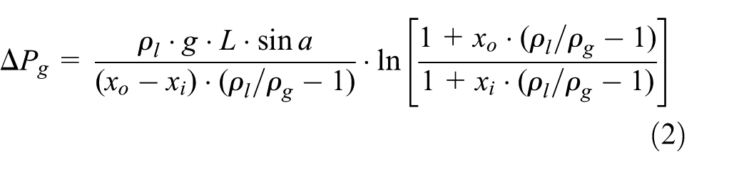
where ρl is the density of the liquid phase, ρg is the density of the gas phase, xo is the steam quality of the outlet, xi is the steam quality of the inlet, and a is the angle of the tube

For the adiabatic tube test section


The two-phase frictional pressure drop is given by

where ΔPl0 is the single-phase saturated-water frictional pressure drop and is obtained by the Blasius correlation;
27
the coefficient
The steam quality at the axial location z of the test section is calculated using the thermal balance equation

where Dn, Ln, and qn are the inside diameter, heated length, and heat flux, respectively, of the nth pre-heater. Lsc is the sub-cooled length within Ll, which can be calculated by
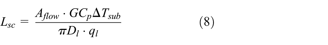
where ΔTsub is the temperature variation between the saturated fluid temperature and inlet fluid temperature of the first pre-heater. In the experiments, the heat absorption efficiency was calibrated, and the system heat balance was ensured to be maximized. Thus, the steam quality in this study is considered an equilibrium steam quality. The heat absorption efficiency of the test section is estimated from the enthalpy alteration of single-phase water and input electric power and is given by

wherein ΔH and QE are calculated as follows

The estimated uncertainties in the measured and calculated parameters are delineated in Table 2.
Uncertainties in measured and calculated parameters.

Experimental results and discussion
It is generally considered that the steam quality, pressure, and mass flux influence
Effects of steam quality and pressure on
Figure 4 illustrates the experimental data of the two-phase frictional multiplier plotted against steam quality and system pressure at constant mass flux of 1500 kg/m2 s and constant heat flux of 500 kW/m2 in the internally ribbed heated tube. The ordinate represents the two-phase frictional multiplier, and the abscissa represents the steam quality. Considering the example of a pressure of 9 MPa, it is observed in Figure 4 that the two-phase frictional multiplier increased with increasing steam quality within a certain range of steam quality. This phenomenon demonstrates that the frictional pressure drop in the steam phase was higher than that in the liquid phase. However, when the steam quality reached a certain value (approximately 0.7), the rate of increase reduced.

Effects of pressure on two-phase frictional multiplier in heated tube.
As illustrated in Figure 4, the pressure significantly impacted the two-phase frictional multiplier, which decreased with increasing pressure. However, the decreasing trend was gradual until the near-critical pressure region was reached. The two-phase frictional multiplier was approximately equal to 1 within the whole steam-quality region, indicating that the two-phase frictional pressure drop was similar to that of the single-phase frictional pressure drop when the pressure approached the near-critical value.
Effects of mass flux on
Figure 5 displays the variations in two-phase frictional multiplier with steam quality and mass flux at a pressure of 16 MPa and heat flux of 300 kW/m2 in the heated test section. From Figure 5, it is observed that the mass flux had negligible effect on two-phase frictional multiplier in the range of the test parameters. In the low steam-quality region, the frictional multiplier converged to a line, indicating that the frictional multiplier is insensitive to mass flux. With the increase in the mass flux, the frictional multiplier in the high steam-quality region increases marginally. A local hump appeared in the proximity of steam quality of approximately 0.6 under the high mass fluxes of 1650 and 1800 kg/(m2 s). It could be owing to flow regime variations in this region. This concept of flow pattern variation in these regions was derived from a comparison of the study results presented by Taklifi et al. 14 and Hewitt and Roberts. 28 From the figure, it could be predicted that the shift to annular flow regimes occurs at a point within the range of x = 0.5–0.8.

Effects of mass flux on two-phase frictional multiplier in heated tube.
Two-phase frictional multiplier in heated and adiabatic tubes
Figure 6 illustrates the difference of two-phase frictional multiplier between the heated test tube and adiabatic test tube at mass flux of 1200 kg/(m2 s) and pressures of 13 and 21 MPa. First, the effects of operating pressure on pressure drop are remarkable. The two-phase frictional multiplier decreases with increasing pressure under the same steam quality; furthermore, the difference of frictional multiplier between the two pressures increases with increasing steam quality.

Frictional multiplier difference in heated and adiabatic tubes.
Second, as can be observed from Figure 6, when P = 21 MPa, the frictional multiplier of both adiabatic and heated tubes gradually increase with the increase in the steam quality. And there is little difference between the frictional multiplier of adiabatic tube and heated tube. It is meant that the two-phase frictional pressure drop is equal to the single-phase frictional pressure drop when the pressure is around critical pressure. While P = 13 MPa, the frictional multiplier of the heating tube is always bigger than the adiabatic tube under the same steam quality. And the frictional multiplier in the adiabatic tube keeps increasing. But the frictional multiplier in the heated tube increases first and then remains a certain value (steam quality of 0.7–1). This phenomenon can be explained as follows: (1) the inside wall of the internally ribbed tube encompasses liquid water because of the liquid-phase centrifugal force flowing in the internally ribbed tube at lower steam quality, which leads to the increase in the frictional multiplier when the steam quality is less than 0.7. (2) When the steam quality is bigger than 0.7, the fluid flowing at a higher speed could rupture the liquid membrane in the proximity of the internal wall when the steam quality exceeded a certain value in the heated tube compared with the adiabatic tube; simultaneously, the flow pattern of the higher speed fluid in the high steam-quality region shifts to a mist flow at a lower pressure. The two reasons together lead to the frictional multiplier in the heated tube to increase first and then remain a certain value.
It is observed in Figure 6 that in the two-phase flow region, the frictional multiplier of the heated tube is higher than that of the adiabatic tube. However, in the single-phase flow region, the frictional factor in the heated tube is smaller than that in the adiabatic tube, which is illustrated in Figure 7. The phenomenon might be a result of the enhancement of flow disturbance on the wall surface in the two-phase flow region. In the single-phase flow region, the friction factor f was a function of only the Reynolds number,
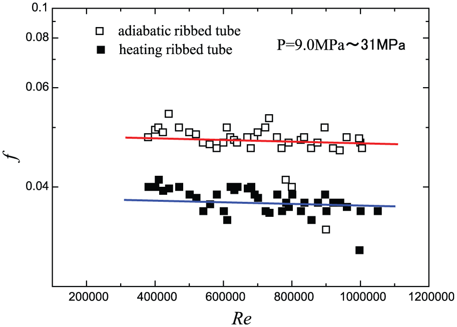
Variation of single-phase frictional factor with Reynolds number.
Correlations of two-phase frictional pressure drop
As described before, the two-phase frictional pressure drop was calculated by equation (6). The two-phase frictional multiplier could be correlated as follows

where


where

Combining equations (12a)–(12d) yields

By introducing a correction factor k, equation (13) can be expressed as follows
Based on the experimental results in Figures 4–6, we found that the two-phase frictional multiplier is related to steam quality x, operating pressure P, and mass flux G. Meanwhile, the function

Therefore, the purpose of the experimental study is to obtain the function
The formula of two-phase frictional multiplier
Based on the multivariate linear regression analysis, we obtain the following correlation for adiabatic internally ribbed tube

The corresponding application conditions are the pressure range 9–21.5 MPa and mass flux range 400–1800 kg/(m2 s). The comparison between predicted two-phase multiplier and experimental data is displayed in Figure 8. The average error of equation (16) is 5.4% with a standard deviation of 16.9%. In all, 32.2% of the test data lie within the ±10% error band, and the entire set of test data lie within the ±40% error band.

Comparison between experimental and calculated two-phase multiplier using equation (16) for adiabatic tube.
Fitting the formula of two-phase

The corresponding application conditions are the pressure range of 9–21.5 MPa, mass flux range 400–1800 kg/(m2 s), and heat flux range 300–600 kW/m2. Figure 9 presents the experimentally obtained values of the two-phase multiplier plotted against those obtained by equation (17). The predictions of equation (17) are satisfactory, with an average error of 4.7% and a standard deviation of 11.1%. In all, 53.8% of the test data lie within the ±10% error band, and the entire set of test data lie within the ±30% error band.

Comparison between experimental and calculated two-phase multiplier using equation (17) for heated tube.
Conclusion
The single-phase frictional factor f in the heated tube was lower than that in the adiabatic tube, while the two-phase frictional multiplier was higher in the heated tube than in the adiabatic tube. The values based on the diverse pressure ranges can be calculated according to correlations expressed by equations (16) and (17).
The pressure significantly affected the two-phase frictional multiplier. Two-phase frictional multiplier
The effect of mass flux on f and
Footnotes
Appendix 1
Academic Editor: Oronzio Manca
Declaration of conflicting interests
The author(s) declared no potential conflicts of interest with respect to the research, authorship, and/or publication of this article.
Funding
The author(s) disclosed receipt of the following financial support for the research, authorship, and/or publication of this article: This work was supported by the Program for Innovative Research Team (in Science and Technology) at University of Henan Province (No. 16IRTSTHN017), Plan for Scientific Innovation Talent of Henan Province (No. 154100510011), and National Natural Science Foundation of China (No. 51406026).