
Abstract
With the rapid development of oil and gas industry, as well as geological exploration industry, the requirements on properties of aluminum alloy drill pipes are increasing. During heat assembly of aluminum alloy drill pipes, the cooling process inside the pipes has a direct impact on the connection performance of pipes. Thus, study of the convective heat transfer coefficient between the cooling water and the internal wall of aluminum alloy pipes is important. Conventional algorithms cannot easily solve the problem of determining the heat transfer coefficient at the complex structure of aluminum alloy drill pipes. Therefore, this article conducts a heat assembly experiment between aluminum alloy drill pipes and steel joints to obtain adequate, accurate temperature data. Based on these experimental data and an inverse heat conduction model, the heat transfer coefficients during the heat assembly process are determined by a finite element program and the differential evolution algorithm. The correlation curve between the cooling water flowrate and the convective heat transfer coefficient obtained in this article is important in the accurate prediction of heat transfer capacity and temperature field distribution during heat assembly at different cooling water flowrates. The analysis results show that the heat transfer coefficients are nonlinear functions of cooling water flowrates. The temperature is highest at location A1 and gradually declines backward along the axis of the drill pipe. The heat transfer coefficient gradually declines backward along the axis of the drill pipe. The increasing flowrate of cooling water will cause the convective heat transfer coefficient along the axis of the drill pipe to escalate irregularly.
Introduction
With the rapid development of the oil and gas industry, as well as the geological exploration industry, drilling depth has also been greatly increasing, which increases the requirements of the working properties of drilling pipes. Compared to steel drill pipes, aluminum alloy drill pipes are more advantageous in well drilling because of their low specific gravity, corrosion resistance under various harsh environments, non-magnetic property, and stable mechanical properties. For drilling rigs of the same hook load capacity, aluminum alloy drill pipes allow significantly reduced power consumption and time of drilling operations and increased drilling capacity compared to ordinary steel drill pipes. Aluminum alloy pipe bodies are usually assembled with regular steel joints to form drill strings. In this article, the connection between aluminum alloy pipe bodies and steel joints is achieved by an interference fitting-based heat assembly technique. In such a heat assembly process, cooling inside pipes is crucially important. Thus, the study of the convective heat transfer coefficient between the cooling water within the drill pipe and the internal wall of the aluminum alloy pipe is important.
MI Lourenco et al. 1 conducted extensive research on the structural strength of aluminum alloy drill pipes, with the aim of improving the fatigue resistance of these components by selecting the appropriate aluminum alloys and strengthening the threaded connection of steel joints. MI Lourenco et al. introduced experimental testing procedures targeting different pipe materials (Al-Zn-Mg alloys) and sizes, and performed numerical analysis.2,3
During assembly, steel joint is heated and then screwed to the end of aluminum alloy pipe; after cooling, the assembly can provide reliable permanent connection. Vadim Tikhonov et al. studied in detail the stress distribution within the assembly and calculated the stress concentration factors under different axial loads, flexural moment ranges, interference friction coefficients, and interference magnitudes of connection. Furthermore, they conducted fatigue testing on full-size aluminum alloy pipe connections using four-point bending fatigue machine and resonant fatigue test machine, and comparatively verified the findings with simulation analysis results. 4
Vadim Tikhonov et al. proposed that a fixed torque method and heat assembly method are currently available for the connection of aluminum alloy drill pipes with steel joints. In the first method, the male and female steel joints are tightened on an aluminum alloy drill pipe with sufficiently high torque, while in the second method, the steel joint is heated and then screwed to the end of the aluminum alloy pipe, and after cooling, the joint contracts to form a reliable permanent threaded connection of an “aluminum alloy drill pipe–steel joint.” In this article, intensities of tensile loads and alternating bending loads borne by these two types of connections after assembly are analyzed. Subsequently, tensile testing is performed on full-size aluminum alloy drill pipes on Krylov Shipbuilding’s MUG-3000 load test machine to analyze the results of the two assembly methods.5,6
J Mao 7 studied the interference connection of an aluminum alloy drill pipe body and steel tool joint assembly; both the assembly technique and the temperature are introduced.
In recent years, various inverse heat conduction models have been developed to evaluate the heat transfer coefficient by many researchers. Inverse heat conduction algorithms, which utilize measured time–temperature data, have been applied successfully to determine the inverse heat conduction.8–10 L Zhang et al. 11 successfully developed an inverse conduction model to collect temperature data within an aluminum casting in proximity to the mold. A modified specific heat method was used to account for latent heat evolution in which the rate of change of the fraction solid with temperature was held constant. B Hadala et al. 12 studied the influence of the finite element model on the inverse determination of the heat transfer coefficient distribution over a hot plate cooled by laminar water jets. AK Nallathambi and E Specht 13 and PL Woodfield et al. 14 used the two-dimensional finite element model for the numerical analysis. E Hetmaniok et al.15,16 introduced the ant colony optimization algorithm and the clonal selection algorithm to the inverse heat transfer algorithm.
An experimental investigation of the heat transfer coefficient on a hot steel plate during water jet impingement cooling was conducted by H Wang et al. 17 The plate thickness was 25 mm, and the plate temperature was measured by four thermocouples located 2.5 mm below the cooled surface. The solution was obtained based on an axially symmetrical heat conduction model. A similar inverse solution for one spray nozzle was proposed by Z Malinowski et al. 18 Inverse solutions based on axially symmetrical models and a three-dimensional heat conduction model are required for plate cooling by a set of water jets, water sprays, or water curtains.
IA Fardi et al. 19 studied the effect of pressure on the heat transfer coefficient at the interface of A356 aluminum alloy. They correlated the interfacial heat transfer coefficient (IHTC) to applied external pressure, in which IHTC at the interface between A356 aluminum alloy and a metallic mold during the solidification of casting under different pressures was obtained using the inverse heat conduction problem method. Furthermore, R Xu et al. 20 studied the influence of pressure and surface roughness on the heat transfer efficiency of aluminum alloy. The results showed that both the heat flux and heat transfer coefficient increase with increasing spray pressure.
In this article, we perform inverse heat conduction algorithms for an aluminum alloy pipe heat assembly process. There are five sections in this article. Section “Heat assembly experiment and the temperature field measurement” describes the heat assembly experiment and then presents the method of measuring the temperature field at the threads of an aluminum alloy drill pipe and the measurement results. Section “Inverse solution to heat transfer coefficient” first describes the inverse heat conduction model and then describes the procedure for inversely solving the heat transfer coefficient. In section “Results and discussions,” the calculated temperature results and the convective heat transfer coefficient results are studied. Section “Conclusion” summarizes the conclusions.
Heat assembly experiment and the temperature field measurement
Because aluminum alloy drill pipes cannot withstand frequent screwing and unscrewing in the drilling process due to low wear resistance, an assembly of a pipe body with a steel joint is needed to form a drill string, so that the screwing and unscrewing operations can be borne by the steel joint. To achieve a reliable connection between aluminum alloy drill pipes and steel joints, a heat assembly technique is employed. In the so-called heat assembly process, the steel joint is first heated to a certain temperature to allow expansion and then screwed onto the aluminum alloy pipe in the hot state. After cooling, the necessary preload is obtained at the threaded connections, the interference fit is achieved, and the permanent fixed connection is attained to fulfill the purpose of a reliable connection.
Description of heat assembly experiment
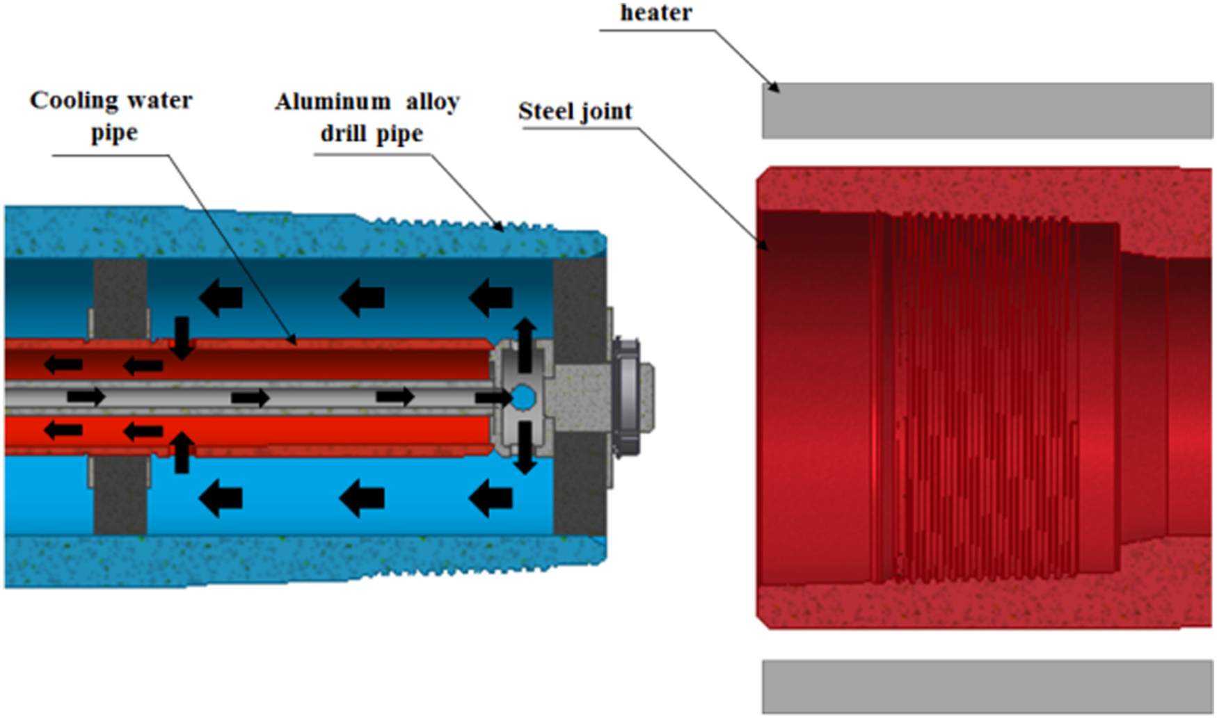
As shown in Figure 1, the aluminum alloy drill pipe is stationary. The heating mechanism uses an induction heater to heat the steel joint to the desired temperature. After heating, the steel joint rapidly moves to the left to allow the threads inside the steel joint to contact the threads outside the aluminum alloy drill pipe. Meanwhile, the steel joint starts to rotate quickly and screws into the drill pipe along the threads to complete the heat assembly as shown in Figure 2.
Schematic diagram of startup of heat assembly.

Schematic diagram of completion of screwing in.
To prevent the temperature increase caused by contact of the aluminum alloy drill pipe with the high-temperature steel joint from degrading the mechanical properties of the aluminum alloy material, the cooling mechanism inside the pipe remains open during the entire heat assembly process to cool the pipe interior and thus ensure the temperature at the pipe exterior threads. A closed cycle of internal cooling water is shown in Figure 1. Heat is transferred convectively between the cooling water and the internal surface of the drill pipe. The convective heat transfer coefficient between the two is precisely the main target of study in this article.
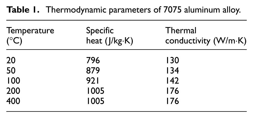
The aluminum alloy material used for the drill pipe is 7075T6, and its relevant parameters are shown in Table 1. The aluminum alloy drill pipe has an outer diameter of Ø147, and other specific dimensions are shown in Figure 3.
Thermodynamic parameters of 7075 aluminum alloy.
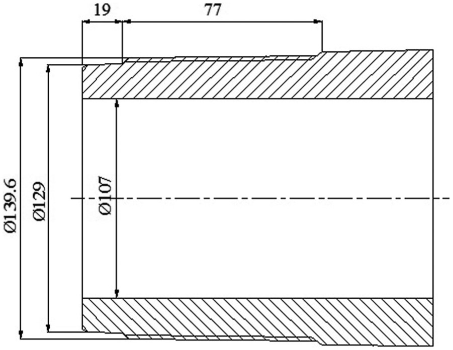
Dimensions of aluminum alloy drill pipe.
Experimental procedures and results
During heat assembly, the temperature at the aluminum alloy drill pipe threads has a significant influence on the mechanical properties of the threads, which further impacts the reliability of the connection between steel joints and drill pipes. Therefore, in this experiment, temperature sensor measuring points A1, A2, and A3 are embedded at the thread of the drill pipe, and its specific location is shown in Figure 4. The heat assembly experiment and temperature measurement are completed on an experimental rig for heat assembly of aluminum alloy drill pipes as shown in Figure 5.
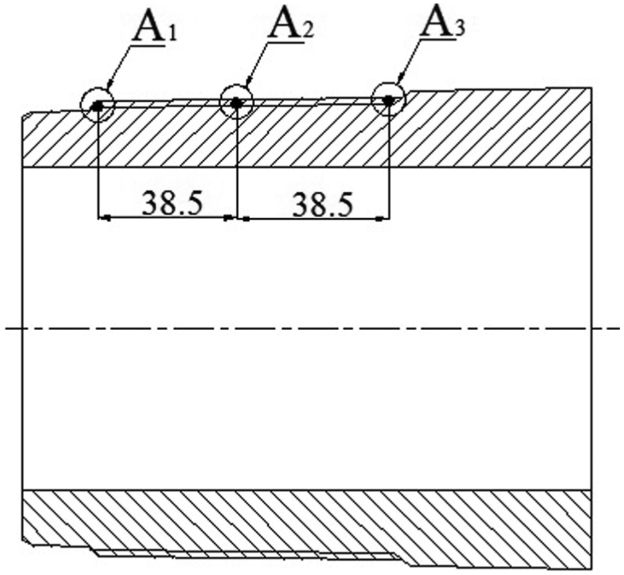
Arrangement of temperature measuring points.

Experimental rig for heat assembly.
The experiments are conducted under internal cooling water flowrates of 5, 10, 15, and 20 L/min, in triplicate, at initial internal cooling water temperature of 27°C, steel joint heating temperature of 400°C, and the same assembly speed. The maximum temperatures T at thread measuring points A1, A2, and A3 under different flowrates of cooling water are obtained as shown in Table 2.
Maximum temperatures of measured value for A1, A2, and A3.

Inverse solution to heat transfer coefficient
In the inverse heat transfer coefficient method adopted for this work, a numerical model of the aluminum alloy drill pipe and steel joint must be developed and then coupled to an inverse algorithm.
Numerical model
In the assembly process, heat from steel joints flows into the aluminum alloy drill pipe mainly along the normal of the thread contact surface. In addition, the thread height is far less than the outside diameter of the aluminum alloy drill pipe, so the influence of thread on the temperature distribution of contact surface is not obvious. Thus, under the assumption that they are in close contact, the contact surface of the aluminum alloy drill pipe and steel joint can reasonably be approximated as a conical surface. Based on simplifying the thread to the conical surface, the overall structure is reasonably approximated as a two-dimensional axisymmetric structure. The cooling water inside the drill pipe flows along the axial direction, and the convection heat transfer is concentrated on the contact part of the cooling water and the drill pipe’s inner wall, so the internal cooling process can be simplified as a boundary of heat convection.
Heat transfer in the aluminum alloy drill pipe and steel joint system can be approximately described by the heat conduction equation
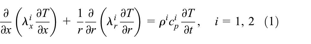
where cp is the specific heat, ρ is the density, λ is the heat conductivity, and i represents different materials: i = 1 represents steel, i = 2 represents aluminum.
The applicable boundary conditions are defined as follows


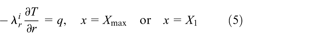
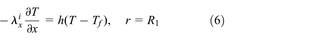
where
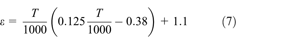
Equation (4) is the radiation boundary, equation (5) is the heat flux density boundary, and equation (6) is the convective heat transfer boundary. The initial temperature distribution is assumed to be uniform throughout the domain. The initial condition is expressed as follows

As shown in Figure 6, the axis of symmetry is the x-axis. The contact surface of the aluminum alloy drill pipe and steel joint is set to the coupled wall. The boundary between the system and the air is set as the radiation boundary as shown in equation (4).
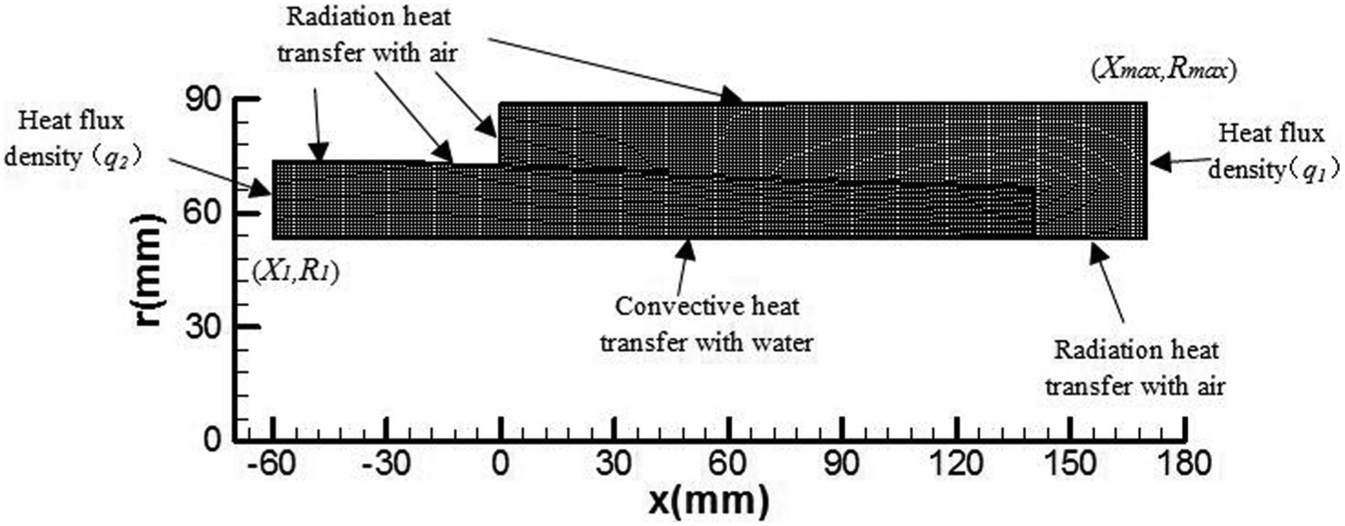
2D axisymmetric domain and boundary.
The domain is meshed using linear elements. The mesh size is 1 mm, and the mesh size of the contact surface is refined as 0.5 mm. The mesh number is 8084. The two-dimensional axisymmetric model in this article was numerically solved by the finite volume method.
Differential evolution algorithm
The differential evolution (DE) algorithm is applied to the inverse heat transfer analysis and to obtain heat transfer coefficient h. DE algorithm was introduced in 1995 by Storn R and Price K for faster convergence and robustness. Prior to using the DE algorithm, several parameters are required. Population size NP, namely, the number of groups of individuals; maximum iterative algebra G; mutagenic factor F, usually ranges
Initialization. Each individual is expressed as

where
2. Mutation operation. For the target vector

where, r1, r2, r3
3. Crossover operation. Take mutation vector
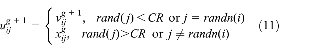
where rand(j) represents the uniformly distributed random numbers, rand(j) ∈ [0,1]; CR is the crossover probability constant.
4. Selection operation. If objective function

Using the DE algorithm to solve the heat transfer coefficient h, the specific steps are as follows:
Initial population. 22 Population size NP = 10, the maximum iteration generation G = 150, the mutagenic factor F = 0.5, and crossover probability CR = 0.9; there is one parameter h, thus each individual has one component, so population dimension D = 1; According to equation (9), we initialize the individual.
Mutation and crossover. According to equations (10) and (11), for each individual within the population, we perform mutation and crossover operation.
Selection. Selecting
Judgment. If achieved specified iteration generation, stop procedure, and output results, otherwise the procedure continues to run.
Inverse heat transfer analysis
Inverse heat transfer algorithms provide a means of using measured temperature history to predict the heat transfer boundary condition. The advantage of using the inverse method is that only the temperatures measured at some proper internal locations of the aluminum alloy drill pipe are required to calculate the heat transfer coefficient. 23
The specific flowchart for the inverse solution of the heat transfer coefficient is shown in Figure 7. In this procedure, the initial heat transfer coefficient
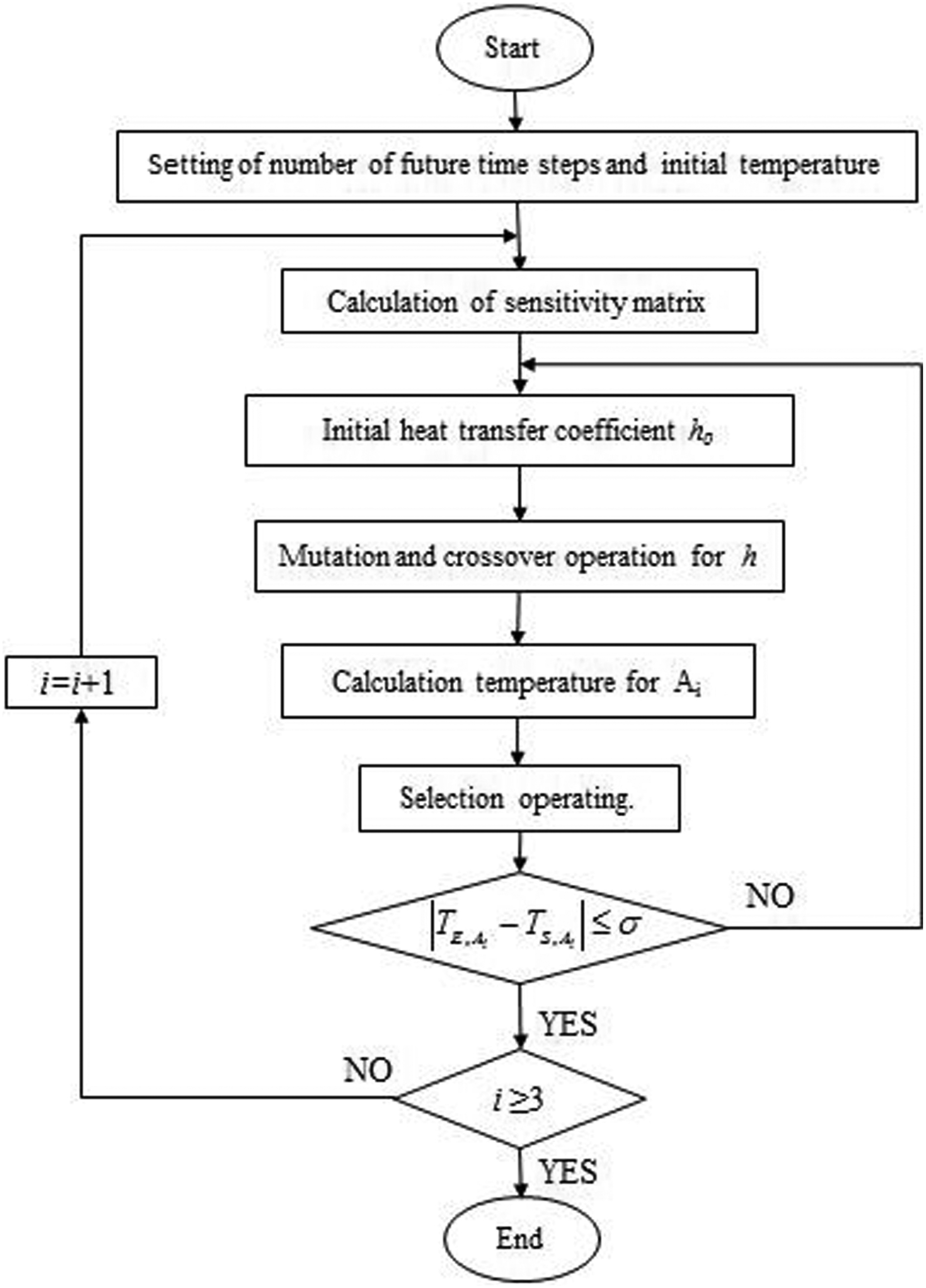
Inverse solution procedure for heat transfer coefficient.
In order to test the mesh independence, 0.5, 1, 1.5, and 2 mm are chosen for the mesh size. According to the inverse solution procedure, based on different mesh sizes, we can obtain the convective heat transfer coefficients h for
Convective heat transfer coefficients for

According to Table 3, we find that the different mesh sizes lead to changes in convective heat transfer coefficient h. The variation range of h is less than 2%, thus, it can be seen that this method has good mesh independence. Considering the iteration time and the accuracy of the results, the 1-mm mesh size is adopted in this article.
Results and discussions
Analysis of temperature results
Based on the results of maximum temperatures for measuring point Ai obtained in section “Experimental procedures and results,” the correlation curve between the cooling water flowrate and maximum measuring point temperature can be obtained as shown in Figure 8.
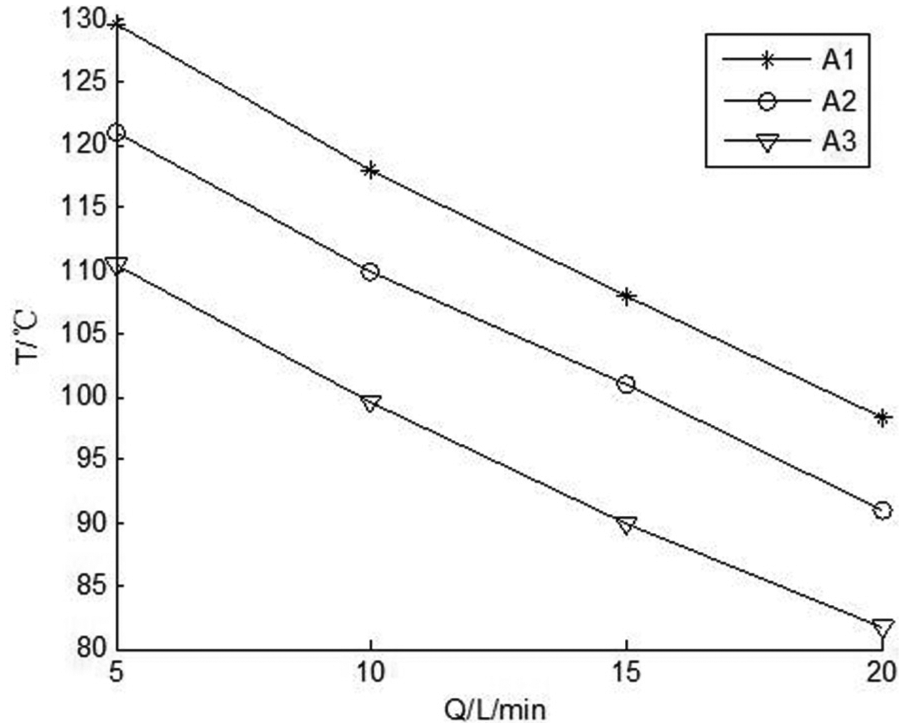
Correlation curve between maximum measuring temperature and cooling water flowrate.
It can be found from Figure 8 that the maximum measuring temperature
It can also be found from Figure 8 that the maximum measuring temperature
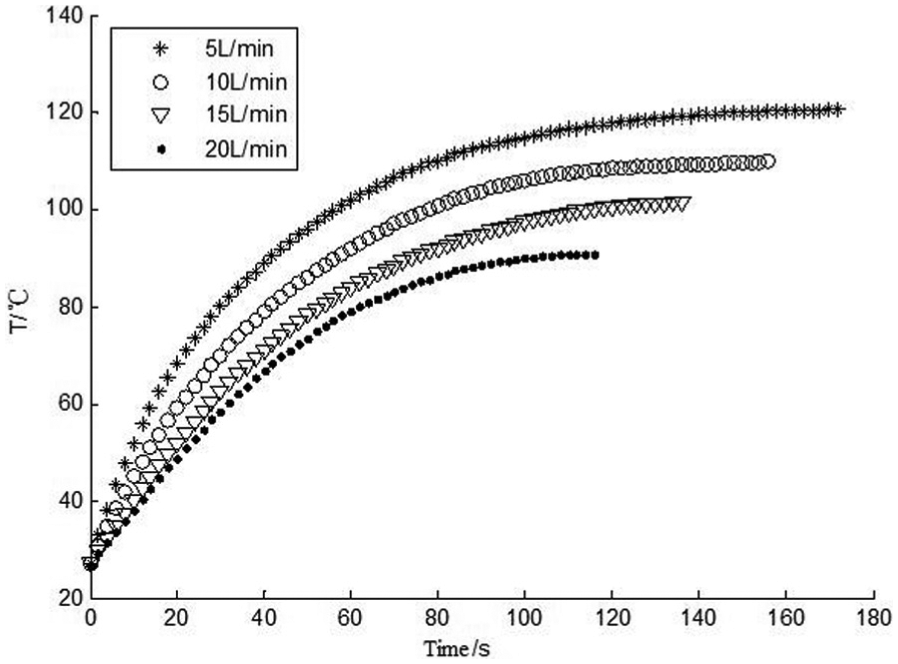
According to the inverse solution procedure in section “Differential evolution algorithm,” the results of the temperature fields for aluminum alloy drill pipes under four different cooling water flowrates can be obtained. The calculated temperature curves before the maximum temperature for point Ai are shown in Figures 9–11.

Calculated temperature curve for A1 before reaching the maximum temperature.
Calculated temperature curve for A2 before reaching the maximum temperature.
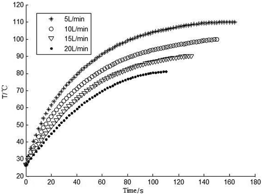
Calculated temperature curve for A3 before reaching the maximum temperature.
As seen in Figures 9–11, the initial thread temperatures are all 27°C. By the interaction of external high-temperature steel joints with internal cooling water, in the beginning stages, temperatures increase quickly, and then temperatures increase gently with increasing contact time between the steel joints and the drill pipe threads. The last points of the curves are maximum temperatures.
As seen, when Q is 5 L/min, the threads reach the maximum temperature at 176 s for point A1. With a continuous increase in the flowrate of cooling water, the time required to reach the maximum temperatures shortens constantly and is only 130 s when Q is 20 L/min. In the same flowrate of cooling water, the time required to reach the maximum temperature shortens constantly from A1 to A3.
Based on the experimental results for measuring point A1, the comparison of measured temperature and calculated temperature for point A1 before the maximum temperature can be obtained is shown in Figure 12. Comparing measured temperature and calculated temperature, we find that in the beginning stage, for measuring point A1, the increasing speed of the measured temperature curve is lower than that of the calculated temperature curve. This is mainly because the beginning stage is the threaded screwing process of the steel joint and aluminum alloy drill pipe, thus, the steel joint and the aluminum alloy drill pipe are not fully in contact. After 38 s, the difference in the measured temperature curve and the calculated temperature curve is reduced rapidly. For each flowrate of cooling water, the maximum temperature error between the measured temperature curve and calculated temperature curve is within 0.01°C, and the times to reach the maximum temperature are the same. Therefore, the method is validated, and the calculated results are reliable.

Comparison of measured temperature and calculated temperature for A1 before reaching the maximum temperature.
Analysis of convective heat transfer coefficient results
According to the inverse solution procedure in section “Inverse solution to heat transfer coefficient,” we obtain the convective heat transfer coefficient h under different flowrates of cooling water as shown in Table 4.
Convective heat transfer coefficients.

The correlation curve between the cooling water flowrate and the convective heat transfer coefficient can be obtained as shown in Figure 13. It can be seen in Figure 13 that the convective heat transfer coefficient between the internal wall of the aluminum alloy pipe and the cooling water increases continuously with increasing flowrate of cooling water. The heat transfer coefficient declines continuously from A1 to A3. Comparing A1,A2, and A3, the heat transfer coefficient of A1 is significantly larger than that of A2 and A3, while the heat transfer coefficient of A3 is close to that of A2.
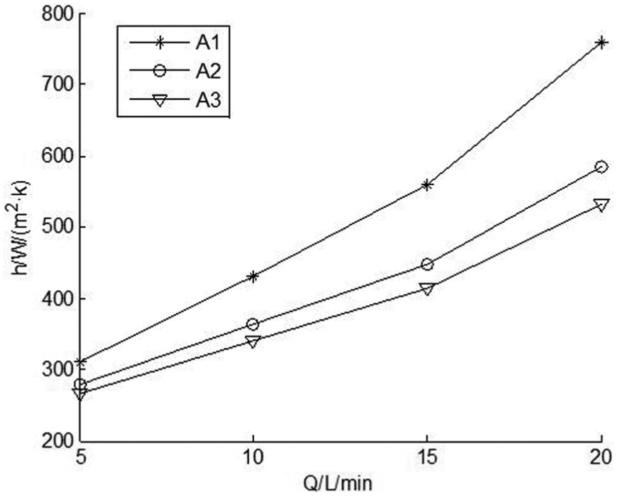
Correlation curve between cooling water flowrate and convective heat transfer coefficient.
This is because cooling water is first sprayed onto the inner wall of the aluminum drill pipe located at A1 at a fast speed, after which it flows to A2 and A3 along the lower stretches of the inner wall at a decreased speed. As a result, the heat transfer coefficient of A1 is significantly larger than the convective heat transfer coefficients of the other two points.
The heat transfer coefficient ratio is introduced to study the distribution of the heat transfer coefficient along the drill pipe axis. The heat transfer coefficient ratio is defined as the ratio of the heat transfer coefficient value at a certain distance from point A1 and at point A1 under the same cooling water flowrates. The heat transfer coefficient ratio can be described by the equation (13)

where R is heat transfer coefficient ratio and hi is the heat transfer coefficient of Ai, i = 2, 3.
Figure 14 shows the variation of the heat transfer coefficient ratio with water flowrate at locations A2 and A3. With increasing water flowrate, the heat transfer coefficient ratio at locations A2 and A3 decreases gradually.

Heat transfer coefficient ratio.
This proves that under the circumstance that cooling water flows at the same speed, the convective heat transfer coefficient will decrease constantly from A1 backward along the axis of the drill pipe, and if the cooling water speeds up, this tendency will become increasingly obvious. In other words, the increasing flowrate of cooling water will cause the convective heat transfer coefficient along the axis of the drill pipe to escalate irregularly.
Conclusion
With the rapid development of oil and gas industry, as well as geological exploration industry, the requirements on properties of aluminum alloy drill pipes are increasing. The connection between aluminum alloy drill pipes and steel joints must be completed by the heat assembly technique, and during heat assembly, the cooling process inside the aluminum alloy drill pipes has a direct impact on the connection performance of the pipes. To this end, this article conducts a heat assembly experiment between aluminum alloy drill pipes and steel joints to obtain adequate, accurate thread temperature data. Based on these data, the inverse solution to the heat transfer coefficient presented is successfully applied to the study of the heat assembly between aluminum alloy drill pipes and steel joints, a two-dimensional finite element program is developed, and heat transfer coefficients are obtained.
The conclusions of the article are summarized as follows:
According to the correlation curve between the maximum thread temperature and the cooling water flowrate, the flowrate of cooling water is recommended to be greater than 20 L/min, ensuring the properties of aluminum alloy.
Based on the analysis of the temperature results, the temperature is highest at location A1 and gradually declines backward along the axis; increasing water flowrate has a significant impact on reducing the maximum temperature at the aluminum alloy surface of drill pipes. In the beginning stages of the assembly, temperatures rise quickly, and then temperatures rise gently with increasing contact time.
Based on the analysis of the convective heat transfer coefficient results, the heat transfer coefficient gradually declines backward along the axis; the heat transfer coefficient of A1 is significantly larger than the heat transfer coefficients of A2 and A3; the heat transfer coefficient of A3 is close to the heat transfer coefficient of A2; and increasing flowrate of cooling water will cause the convective heat transfer coefficient along the axis of the drill pipe to escalate irregularly.
The conclusions obtained in this article are important in the accurate prediction of heat transfer capacity and temperature field distribution during heat assembly at different cooling water flowrates. Therefore, the conclusions have guiding significance for the aluminum alloy drill pipe manufacturers.
This article only studies the relationship between cooling water flowrates and convective heat transfer coefficient. Actually, the initial heating temperature of steel joint and magnitude of interference are also the important factors for heat assembly of aluminum alloy drill pipes. Based on the research in this article, further researches could involve the relationship between convective heat transfer coefficient, initial heating temperature of steel joint, and magnitude of interference.
Footnotes
Academic Editor: Oronzio Manca
Declaration of conflicting interests
The author(s) declared no potential conflicts of interest with respect to the research, authorship, and/or publication of this article.
Funding
The author(s) disclosed receipt of the following financial support for the research, authorship, and/or publication of this article: The work on this paper has been supported by the International S&T Cooperation Program of China (grant no. 013DFR70490), as well as Jilin Province Science and Technology Development Program (grant no. 20130206023GX).