
Abstract
It is well-known that the acoustic performance of double-plate structures deteriorates rapidly around the mass–air–mass resonance frequency. In this study, a mass–spring–damper system connected between incident and radiating plates is used to improve the sound transmission loss at low-frequency ranges. First, a full structural-acoustic modal coupling model is developed to analyze the vibration and acoustical behaviour of the double-plate structures with mass–spring–damper system. Because there are in-phase or out-of-phase vibrations between double plates, tuning the natural frequency of the mass–spring–damper system exactly to the mass–air–mass resonance frequency cannot guarantee the maximum improvement on transmission loss. Optimal natural frequency and mass of the mass–spring–damper system were found as a solution of optimization problem with a global cost function defined as frequency-averaged sound transmission loss in the desired frequency range (around mass–air–mass resonance frequency). Finally, some numerical calculation results are presented. The calculated results show that the sound transmission loss of a double-plate structure can be improved significantly using optimally tuned mass–spring–damper system. The results indicate that an overall improvement of 12 dB below 1000 Hz can be achieved when the mass of the mass–spring–damper system equals to 10% weight of the double-plate structure.
Keywords
Introduction
Nowadays, double-plate structures are widely used in the aerospace and building industries when good sound insulation characteristics have to be achieved. 1 Typical examples include double-glazing windows and aircraft fuselages. However, the main drawback of such structures is a decrease in low-frequency transmission loss around the mass–air–mass resonance.2–6 Here, it can become even poorer than that of a single plate. It means that today’s sound isolation performance of the double-plate structures still requires significant improvement especially in regard to low frequencies, which dominate traffic and aircraft noise. In an effort to improve the transmission loss through the double-plate structures, many techniques have been developed, which can be broadly classified into active control and passive control methods.
One possible solution is by means of active control methods.7–11 However, there are some limitations seriously compromising the active control system for practice applications, such as requirement of additional power support for control energy, complex controller design and robustness problem.
Another possible solution is to use the passive control method. For example, it is possible to apply an arrangement of optimally tuned Helmholtz resonators (HRs) to increase the acoustical damping level inside the cavity between the double plates. Mason and Fahy 12 proposed to control sound transmission through an infinite double-plate using HRs. A theoretical model and experimental verification for passively control finite double-plate structures using HRs were introduced in our previous papers.13,14 Numerical and experimental results show that the optimally tuned HRs can indeed be used to effectively control the sound transmission through a double-plate structure. Idrisi et al. 15 used heterogeneous (HG) blankets, which consist of poroelastic material with small embedded masses, to control sound transmission through the double-plate structures. The numerical model using the impedance and mobility method was presented, and the calculated results were experimentally verified in Idrisi et al. 15
In this study, a mass–spring–damper (MSD) system is imposed to improve the sound transmission loss around mass–air–mass resonance frequency. First, the governing equations of a fully coupling structural-acoustic MSD system using modal coupling method are established; then, the effects of the MSD system parameters on the sound transmission are discussed, and the optimally tuned natural frequency and mass of the MSD system are discussed in detail; finally, some useful conclusions are drawn and illustrated by numerical results.
System modelling
A model is demonstrated in Figure 1 to describe the mechanical behaviour of a double-plate structure with an MSD system. Two parallel plates with length Lx and width Ly, denoted by incident plate and radiating plate, are located in an infinite rigid baffle. An MSD system is installed between two plates at (x0, y0). The incident plate is set to be z = 0 and the radiating plate at z = Lz. The radiated acoustic field of the double-plate structure is assumed as an acoustic-free field.

(a) A double-plate structure with an MSD system installed between incident and radiating plates and (b) free body diagram of the MSD system.
Because there is no excitation source in cavity, the acoustical field of the cavity can be described in homogeneous wave equation by wave equation 1

with boundary conditions

where ρo and co are the density and sound speed of the air, respectively. p is the sound pressure in cavity. wi and wr are displacements of incident plate and radiating plate, respectively.
Due to the reaction force of the spring–damper–mass system, the vibration of the incident and radiating plate are governed by the following equations


with
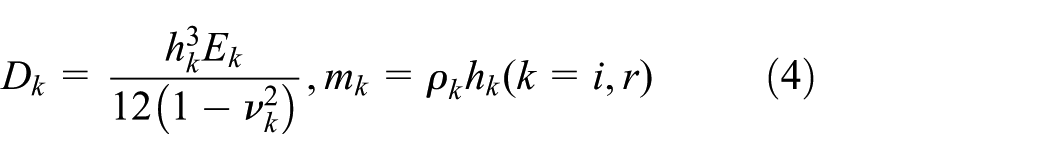
where
The velocity distribution of the plates and the cavity pressure can be represented by a series of expansions 13
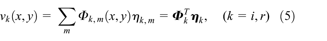

where ηk,
m
and Pn are the mth structural modal coordinates and the nth sound pressure modal coordinates, respectively. Φk,
m
(x, y) and
Substituting equations (5) and (6) into equations (1)–(3), using the orthogonal properties of the mode shape functions and taking the damping ratio of plates and fluid in cavity into account, the complete set of equations for the double-plate system can be expressed in matrices form as


where


where ρo and co are the density and sound speed of air, respectively.

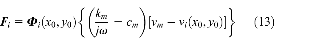

where vm is the velocity of the mass.
Notice that the vibration of the MSD system can be expressed as a single-degree-of-freedom system, that is

where mm, cm and km are the mass, damping and stiffness of the MSD system, respectively.
From equation (15), the velocity of the mass can be obtained

with
Substituting equation (16) into equations (13) and (14),
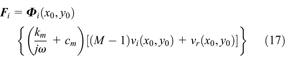
From equations (7)–(9), we get

with
Substituting equations (17) and (18) into equation (19), we get

where

Substituting equations (17), (18) and (20) into equations (5) and (6), the modal velocity with MSD system can be expressed as


where

Notice that the velocity vi (x0, y0) and vr (x0, y0) can be written as

Substituting equation (24) into equations (20)–(22), we get


Combining equations (25)–(27), we can get the fully coupled structural-acoustic responses for the double-plate structure with MSD system.
Sound transmission loss
The sound power of the radiating plate can be obtained using the radiation mode approach16,17

where
The sound transmission loss TL is defined as the sound power incident on the incident plate divided by the sound power radiated by the radiating plate

Some of the results quoted in the following sections will be expressed in terms of the frequency-averaged transmission loss and defined as
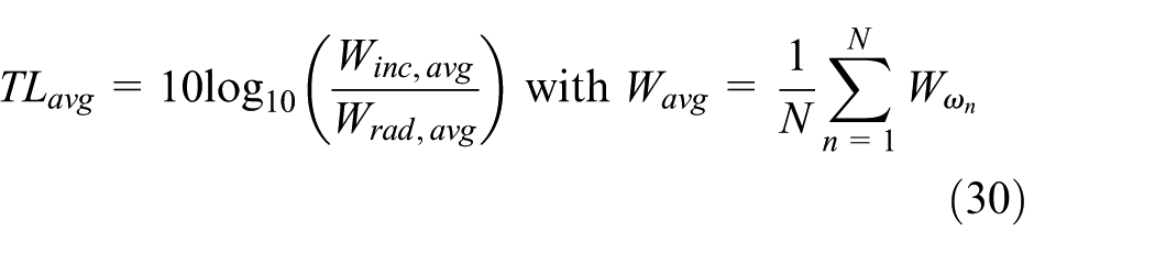
where [ω1, ωN] is the frequency range of interest.
Numerical calculations
A double-plate structure with the mass–air–mass resonance frequency at 155 Hz studied by Panneton and Atalla 18 with the finite element model is restudied. The boundary conditions for both plates are simply supported. The physical parameters of the structure are as follows: Lx × Ly × h = 350 mm × 220 mm × 1 mm and the depth of cavities Lz = 76.2 mm. The density, Young’s modulus and Poisson’s ratio of each plate are 2814 kg/m3, 71 × 109 N/m2 and 0.33, respectively. The structural and acoustical damping ratios are assumed as 1% in this study. The incident plate is excited by a random incident acoustic wave of 1-Pa amplitude to make sure that all the structural modes are well excited. The MSD system is assumed to be located at the centre of each plate.
To verify the proposed analytical model in section ‘System modelling’, assume that pin in equation (2) is a normal incident plane wave for comparison purpose. The sound transmission TL without MSD system is calculated using the proposed method. The results are presented up to 1000 Hz in Figure 2. A good agreement is observed with results shown in Panneton and Atalla, 18 at least up to maximal finite element calculation frequency (500 Hz). From Figure 2, it can also be found that the double-plate structure has relatively poor sound insulation at certain low frequencies due to effective coupling of the structural modes and acoustical modes in the sound field.
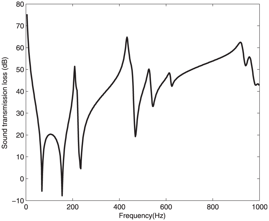
Normal incidence sound transmission loss of a double-plate structure with the same physical parameters listed in Panneton and Atalla. 18
Spring stiffness effect on sound transmission loss
Before analysing the control performances produced by the MSD system, it is interesting to consider the effects produced by the spring of the MSD system.
Assume that the values of the mass and damper of the MSD system are zero. At this time, only a spring is connected between incident and radiating plates. Figure 3 shows the effect of the values of the spring stiffness on sound transmission loss. Figure 4 shows the vibration distributions at 69 (the first natural frequency of uncoupled structural mode) and 155 Hz (the mass–air–mass resonance frequency without the MSD system). From Figure 3, it is found that the sound transmission loss is independence to the spring values around 69 Hz. This seems surprising at first glance but the cause is due to the fact that the plates move in phase, as shown in Figure 4(a). It indicates that the distance between two plates around 69 Hz remains the same, and the spring force is zero around 69 Hz. The mass–air–mass resonance frequency is increased with the increase in the values of the spring stiffness. This is because the stiffness of the plates is increased due to increase in spring force. Furthermore, it can be found that introducing a spring between plates cannot improve the sound transmission loss. This conclusion agrees well to Cheng et al. 3 and is quite understandable because the spring can be seen as a mechanical link in this case.
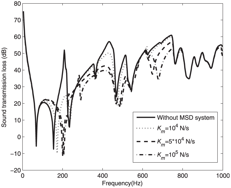
The sound transmission loss under various values of the spring stiffness.

The vibration distributions without MSD system (a) at 69 Hz and (b) at 155 Hz.
Mass of the MSD system effect on sound transmission loss
According to classical tuned vibration absorber theory, 19 if the mass is given, the optimal natural frequency and damper values for the MSD system are

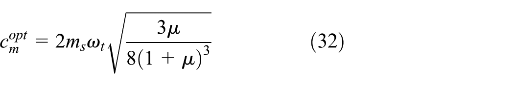
where ωt is the target frequency,
Notice that the sound transmission loss reduces quickly around the first natural frequency (69 Hz) of the uncoupled structural mode and the mass–air–mass resonance frequency (155 Hz), as shown in Figures 2 and 3. So, the MSD system should be targeted to control the first uncoupled structural mode or the mass–air–mass resonance mode, respectively. The numerical results are presented in Figures 5 and 6 with the optimal parameters of the MSD system given by equations (31) and (32). Comparing Figures 5 and 6, it can be found that the MSD system tuning to the first uncoupled structural mode can obtain the better control performance. Because in this case, not only the target first uncoupled structural mode can be controlled but also the sound transmission around mass–air–mass resonance is damped. However, when the MSD system is targeted to control mass–air–mass resonance, the sound transmission loss around the first uncoupled natural frequency cannot be improved. From Figures 5 and 6, it can be found that the MSD system connected between incident and radiating plates can affect not only the targeted mode but also the other modes, due to the in-phase and out-of-phase vibrations between two plates (as shown in Figure 4). It means that the optimal natural frequency obtained from equation (31) might not be the best solution for double-plate structures. Because the effect on the neighbouring untargeted modes is neglected in equation (31), we should search a new solution to optimize the natural frequency of the MSD system. It will be discussed in next section.
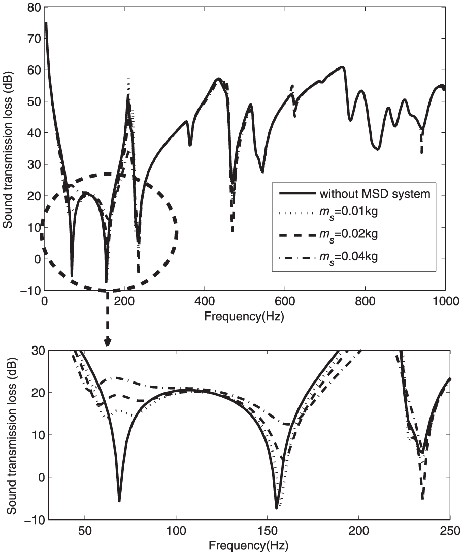
The sound transmission loss TL when the MSD system is targeted to control the first uncoupled structural mode.

The sound transmission loss TL when the MSD system is targeted to control the mass–air–mass resonance mode.
The optimally tuned natural frequency and mass of the MSD system
In traditional MSD system applications, the MSD systems are mainly used for vibration control. So, a large mass of the MSD system is always favourable for vibration control case. However, in this study, the main aim is to improve the sound transmission loss at low frequencies, it means that the sound power of the radiating plate should be controlled. It is well-known that the sound power is the function of surface velocity distribution, the different distribution of surface velocity makes different contribution to sound power. Therefore, merely minimizing the vibration levels of the structure at chosen coordinates does not guarantee minimization of the radiated sound power.16,17 It means that adding the mass of the MSD system cannot guarantee that the improvement on transmission loss TL is maximized over a reasonably wide frequency range (0–1000 Hz in this case). To obtain the optimal natural frequency and mass of the MSD system, we use the frequency-averaged sound transmission loss TLavg as the global cost function, that is
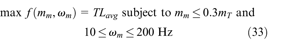
First of all, assume that the natural frequency of the MSD system is given. Figure 7 shows the TLavg improvement as a function of the mass of the MSD system. It is clear that the TLavg improvement does not increase linearly with the mass. There is an optimal mass for each given natural frequency. For further increase in the mass, the TLavg improvement will be reduced. It means that adding mass of the MSD system does not necessarily increase the sound transmission loss.
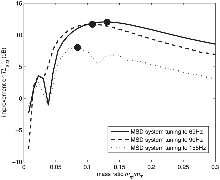
The improvement of TLavg as a function of both mass and tuned natural frequencies of the MSD system (circle marks: the optimal mass for each case).
From Figure 7, it can also be found that the natural frequency of the spring–mass–damper (SMD) system targeted to the mass–air–mass resonance mode cannot obtain the best TLavg improvement. For example, when the natural frequency of the MSD system is tuned to 69 or 90 Hz, two clear maximums of 12 and 11.7 dB TLavg improvements are observed. However, when the natural frequency of the MSD system is tuned to mass–air–mass resonance frequency (155 Hz), the best TLavg improvement is only 8 dB.
Notice that the effect of MSD system is adding damping on both plates of the double-plate structure, and Figure 8 compares the sound transmission performance between the plate with different damping ratios and with MSD system (tuned to 69 Hz with optimal mass). In Figure 8, the damping ratios of the incident and radiating plates are assumed to be the same, that is,

Comparison the sound transmission loss TL between damping ratio effect and MSD system.
To further investigate the control performance of the MSD system, the improvement of TLavg as a function of both mass and tuned natural frequencies of the MSD system is presented in Figure 9. Unlike the traditional tuned vibration absorber theory, 19 it can be found that the optimal natural frequency depends on the mass of the MSD system. It means that the optimal natural frequencies can be far removed from the mass–air–mass resonance frequency. As mass increases, the optimal natural frequency changes from 100 to 20 Hz. Furthermore, it can be found that a TLavg improvement of 12 dB can be achieved when the natural frequency of the SMD system is 85 Hz and mm/mT = 10%.
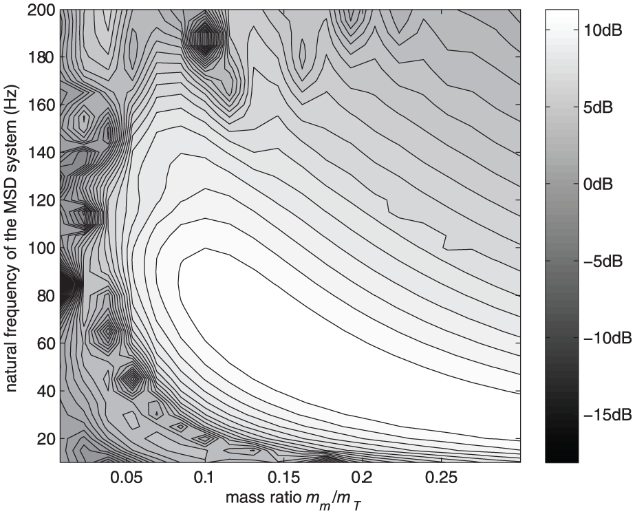
Contour plot showing the improvement of TLavg as a function of both masses and tuned natural frequencies of the MSD system.
As the optimal mass and tuned natural frequency are found, another important parameter effect on the control performance is the location of the MSD system. Assume that the MSD system is tuned to 69 or 90 Hz with optimal mass (as shown in Figure 7), and the improvement of TLavg as a function of the locations of the MSD system are presented in Figure 10. From Figure 10, it can be found that optimal location for MSD system is near the centre of the plate, and the control performance reduces quickly when the MSD system is moved to the plate frame.

Contour plot showing the improvement of TLavg as a function of the locations of the MSD system: (a) tuned to 69 Hz and (b) tuned to 90 Hz with optimal mass.
Conclusion
In this study, the passive control of sound transmission through a double-plate structure using an MSD system connected between incident and radiating plate is presented. A complete structural-acoustic analytical model is presented with the MSD system. The simulation results show that the sound transmission loss can be improved significantly if the mass and natural frequency of the SMD system are optimally tuned, as shown in Figures 7 and 9. Furthermore, it is found that the optimal natural frequency is a function of the mass of the MSD system. It indicates that the mass and natural frequency of the SMD system should be optimized simultaneously to maximize the improvement of the transmission loss obtained the best the improvement of the sound transmission loss over a wide frequency bandwidth.
Footnotes
Academic Editor: Jiin-Yuh Jang
Declaration of conflicting interests
The author(s) declared no potential conflicts of interest with respect to the research, authorship, and/or publication of this article.
Funding
The author(s) disclosed receipt of the following financial support for the research, authorship, and/or publication of this article: This work was supported by the National Natural Science Foundation of China under grant nos 11464031 and 51265037, and the Aeronautical Science Foundation of China under grant no. 2015ZA56002.