
Abstract
This article studies energy dissipation of a friction damper (due to stick–slip vibration) in the context of harmonic excitation. There are numerous applications of such friction dampers in engineering. One particular example is a new kind of under-platform dry friction dampers for aero engines. The model consists of a clamped cross-like beam structure and two masses (friction dampers) in contact with the short beam of the cross. The two masses are allowed to slide along two extra short vertical clamped beams. They can exhibit three distinct dynamic regimes: pure slip, pure stick and a mixture of stick–slip relative to the short horizontal beam. The finite element method is used to obtain the numerical modes of the structure. The friction at the contact interface between the short horizontal beam and the friction dampers is assumed to follow the classical discontinuous Coulomb friction law in which the static coefficient of friction is greater than the kinetic coefficient. Modal superposition method is applied to solve the dynamic response of the structure with numerical modes. One major finding of this investigation is that there is an intermediate range of the normal contact forces (in stick–slip regime) that provides the best energy dissipation performance.
Keywords
Introduction
In general, friction causes energy dissipation and as such acts as a stabilisation mechanism. For instance, various friction dampers have been used in buildings against vibration caused by earthquakes and under-platform dampers have been used to reduce vibration magnitudes and high dynamic stresses of turbine blades in aero engines. The latter is the motivation of this article. On the other hand, friction can also excite vibration at certain conditions, for example, earthquake motion, sound generated by a bowed string, 1 door hinges, squeaky chalk on a blackboard, brake squeal2,3 that happens in the brake system of an automobile and dry friction dampers in aero engines. These problems are outside the scope of this article.
One interesting form of friction-induced vibration is stick–slip vibration. Popp and Stelter 4 studied two discrete and two continuous models of stick–slip vibration which exhibited various kinds of dynamic behaviour, including chaos. A theoretical analysis of stick–slip instability in systems with 1 degree of freedom was made in Capone et al. 5 Through approximating the discontinuous friction forces by smooth functions, an approximate analysis of dry friction–induced stick–slip vibrations was introduced in Van de Vrande et al. 6 A very interesting review of stick–slip vibration was presented by Feeny et al. 7 Stick–slip and impact motions of a single degree-of-freedom oscillator excited by a frictional moving base and restricted by a unilateral rigid or deformable obstacle were studied in Andreaus and Casini. 8 A shooting method for calculating limit cycles based on a simple and efficient alternate friction model to simulate stick–slip vibrations was presented in Leine et al. 9 On the basis of the local theory of nonsmooth dynamical systems on connectable domains, the force criteria for stick and non-stick motions in harmonically forced, friction-induced oscillators were developed. 10 The critical conditions, amplitudes and base frequencies for the initiation of stick–slip oscillation from pure sliding oscillation were derived by approximate analytical expressions in Thomsen and Fidlin. 11 The effects of the nonsmooth Coulomb friction on the stability and bifurcation behaviour of vibrational systems with self-excitation due to negative effective damping were investigated by Hetzler. 12 In Pascal, 13 the sticking and non-sticking orbits of a 2-degree-of-freedom oscillator subjected to dry friction and a harmonic load were obtained in a closed form. Li et al. 14 developed a model of an elastic disc in sliding frictional contact with a rotating oscillator. Separation of the moving slider form the disc and its subsequent reattachment to the disc were considered, and various dynamic behaviours were discovered. Several friction force models to deal with different friction phenomena in the background of multibody system dynamics were examined and compared, and a particular emphasis on the pure dry sliding friction, stick–slip effect, viscous friction and Stribeck effect was discussed in Marques et al. 15
One important application that involves friction in a vibration environment is aero engine blades equipped with under-platform frictional dampers. Various types of friction models and methods for blade vibration analysis have been investigated. Griffin 16 presented a macroslip model to investigate the resonant stresses of a blade with a dry friction damper. Menq et al. 17 developed a microslip model for analysing the dynamic response of frictionally damped structures in which the friction interface was subjected to high normal loads. A microslip model derived by Menq et al. 17 was improved by Csaba. 18 A new two-dimensional model for point friction contacts was introduced by Sanliturk and Ewins. 19 Cigeroglu et al. 20 adopted a one-dimensional dynamic microslip friction model, including the damper inertia. This microslip friction model was further developed for a two-dimensional distributed parameter model with normal load variation induced by normal motion, 21 in which they explored a harmonic balance method (HBM) for frictionally constrained structures with a varying normal load. It has been found that there is a normal load range that provides effective damping on the steady-state vibration of an aero engine blade under a certain condition, 22 and a bilinear hysteretic model was adopted to calculate the optimum normal loads under different external excitations. 23 However, the blade was modelled as a lumped mass and hence, only one mode could be included in these investigations.22,23 Allara 24 proposed a model to characterise friction contact of non-spherical contact geometries obeying the Coulomb friction law with constant friction coefficient and constant normal load. From this model, the effect of the main contact parameters (contact geometry, material properties, loads) on the contact behaviour could be effectively estimated. In Petrov, 25 the dampers were modelled with the finite elements (FEs). Ostachowicz 26 established an HBM for forced vibration analysis of dynamic systems damped by dry friction forces. Guillen and Pierre 27 introduced a hybrid frequency-time (HFT) method for analysing the steady-state response of the large-scale dry friction–damped structural systems. The correlation of the static/dynamic coupling of the under-platform dampers was investigated by Firrone et al. 28 A new microslip friction model with an elastoplastic shear layer was put forward to analyse dynamic response of a system with under-platform dry friction dampers under high normal force. 29 Mathematical relationships of dry friction force versus relative velocity in friction contact of two bodies were studied by Půst et al. 30 Schwingshackl et al. 31 focused their research on contact interface parameters in a nonlinear dynamic analysis of assembled structures. Among all the available friction models in the above literature review, friction dissipates energy and thus reduces blade vibration; however, friction excited stick–slip motion of the contact interface has been neglected.
This article studies forced vibration of a cross-like structure in frictional contact with two masses. Dry friction forces at the contact interfaces dissipate energy due to the relative rubbing motion at the interfaces and can also cause stick–slip vibration of the surfaces in contact. This structure is meant to represent a simplified turbine blade model with a new kind of under-platform dry friction dampers. Each damper is located at the end of a short cantilever beam and thus is different from those dampers reported in the above-mentioned papers. The effectiveness of these dampers in dissipating vibration energy is assessed through numerical simulation. A numerical approach for determining the dynamic response of the structure with nonsmooth friction contacts is put forward and three distinct types of vibration, including stick–slip vibration between the dampers and the blade platform surface, are studied. This numerical approach can also take any requisite modes of the structure into account.
Theoretical development of nonsmooth vibration
As shown in Figure 1, the structural model consists of two rigidly connected elastic beams in the form of a cross that is clamped to the ground; the vertical beam and the horizontal beam can be considered to represent the blade and the platform of an aero engine, respectively; underneath the horizontal beam, there is a mass connected to a thin and short, vertical elastic cantilever beam on each side. The mass is in frictional contact with the underside of the horizontal beam in the model. Unlike a conventional under-platform damper in an aero engine which is a floating mass actuated by centrifugal force, the friction damper studied here is mounted on the short vertical cantilever beam which can slide along the beam and is forced into contact with the underside of the horizontal beam by a constant force (which can represent the centrifugal force due to rotation in an aero engine).
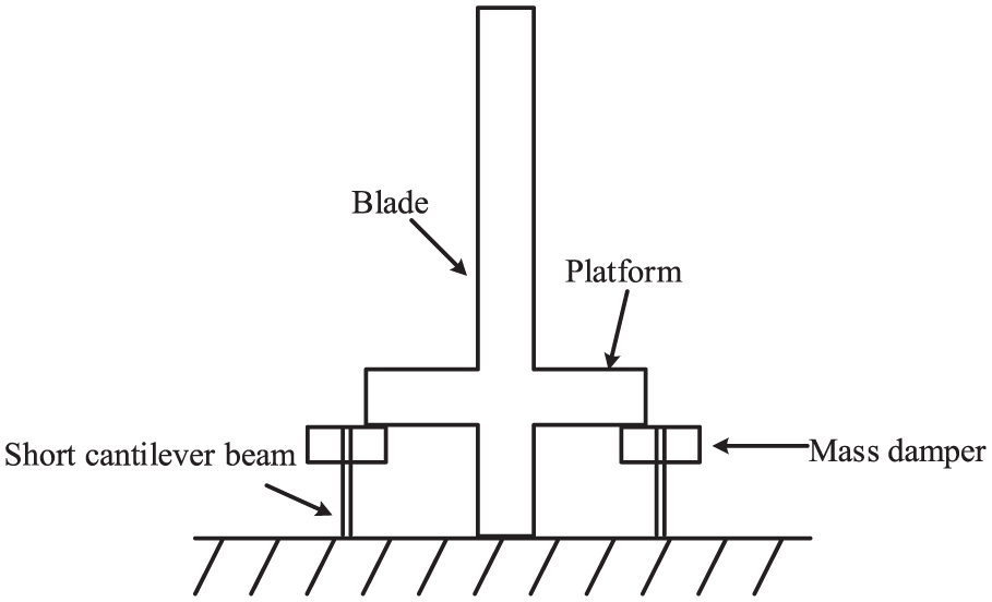
The model of an exemplary structure with friction dampers.
The mechanical model of the structure is illustrated in Figure 2. In the x-y coordinate system, x and y represent the tangential and radial directions, respectively. The plane Cartesian coordinate system x1-y1 (called the left damper coordinate system) is a local coordinate system whose origin is at the left initial contact point, and the plane Cartesian coordinate system x2-y2 (called the right damper coordinate system) is defined similarly. F is the external excitation, which is taken as a harmonic function of time t in this article.

The mechanical model of the cross-like structure.
In this preliminary investigation, the dampers are assumed to undergo horizontal and vertical vibrations, but no rotation. They are in point contact with the horizontal beam and do not separate with the horizontal beam during vibration excited by
A classical discontinuous Coulomb friction model
32
is adopted in this article: before sliding occurs, the friction force balances the applied external force (together with the inertia force) and acts to resist the initiation of sliding; during sliding, the friction force is proportional to the normal force at the contact interface and acts in the direction opposite to the relative sliding. A further assumption is that the static coefficient of friction

The classical Coulomb friction model.
Accordingly, the relationship between the friction force

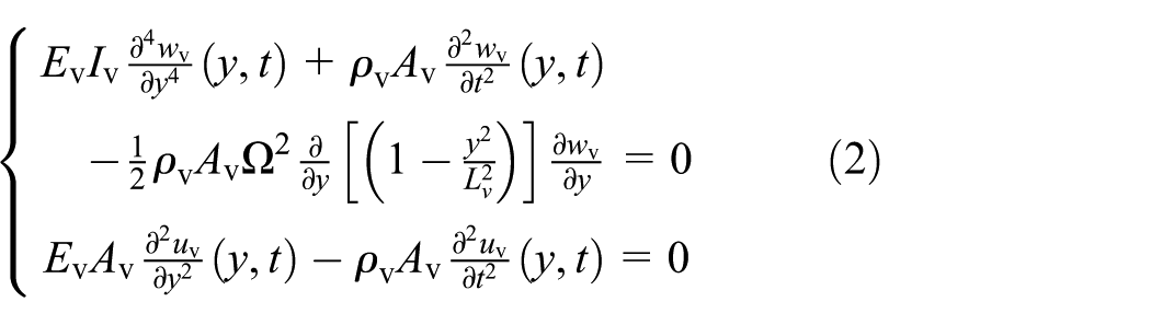
The equations of motion in the local transverse and longitudinal directions of the vertical beam modelled as a rotating Euler–Bernoulli beam 33 (denoted by v) in its local coordinate system are
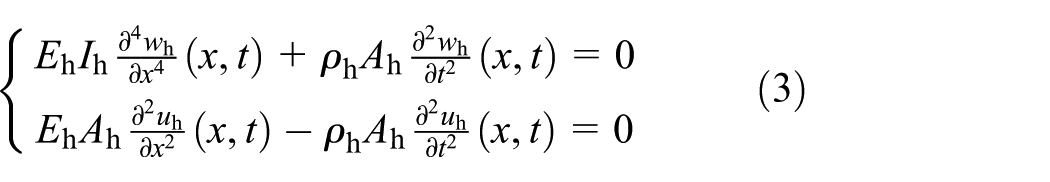
Similarly, the equations of motion of the horizontal beam modelled as an Euler–Bernoulli beam (denoted by h) in its local coordinate systems are
where
For a complicated structure, analytical modes are difficult to obtain. In general, the FE method provides a simple and effective approach to obtain the frequencies and modes of a structure of arbitrary configuration and hence is used. The cross-like structure is discretized with a number of two-node Euler–Bernoulli beam elements. Each node has 3 degrees of freedom: translation along the longitudinal axis of the beam element, denoted by
Using the FE method, the equations of motion can be written in general as

where

equation (4) can be transformed into equation (6) in the modal coordinate vector

where


For simplicity in this preliminary investigation, the normal forces at the contact points are assumed to be a known constant, which satisfy the following equations


where
It is assumed that due to the symmetry of the structure and because normal load

From equation (7),

According to equation (7), the friction force can be found from
It must be checked whether

If this is true, then sticking is taking place; otherwise, slipping is taking place and equation (11) should be used. In either case, the friction force can be determined and hence, energy dissipation can subsequently be calculated.
During the time integration of equation (6), the normal force and the friction force at a contact point must be known. For simplicity, the normal force is assumed to be a known constant, as given in equations (9) and (10); however, the friction force is not known a priori, which depends on whether the damper sticks or slips relative to the horizontal beam. So the vibration states of the damper must be monitored and the precise time instant at which stick switches to slip or slip switches to stick must be captured. This is not a trivial matter. Figure 4 illustrates the basic idea of this matter and how it is solved, using stick to slip as an example.

Close look-up of transition from stick to slip.
In Figure 4,
A computing strategy is devised as follows:
It is assumed at the start of the numerical integration that the damper slips relative to the platform initially.
The friction force is assumed to be
Compute
Solving equation (7) yields
At the end of each time step,
If the above inequality is satisfied, slips continues and go back to step 2 with time stepping forward.
If
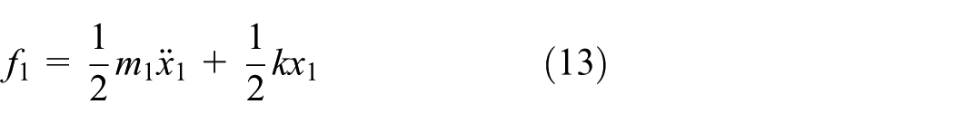
Solving equation (13) to get friction force
Sticking continues and compute
Slipping takes place, the exact time instant when slipping takes place must be determined. Go back to step 8: restart at the previous time instant with a smaller time step, until
The above iteration repeats until the end of simulated time period, during which the damper can keep switching between stick and slip. This is a nonsmooth dynamic process and can take much computing time.
Numerical simulation
In the subsequent numerical simulation, the whole system has the following material and geometric properties: Young modulus
Dynamic analysis and discussion
The responses of the cross-like structure under different normal forces and external sinusoidal excitations are calculated numerically by the Runge–Kutta method. In these numerical examples, the external excitation frequency is fixed as 240 rad/s (38.2 Hz). The time step used in the numerical integrations is 0.0001 s. The simulation results are visualised by means of time histories and frequency spectra. Only some typical results are reported and given in Figures 5–13.

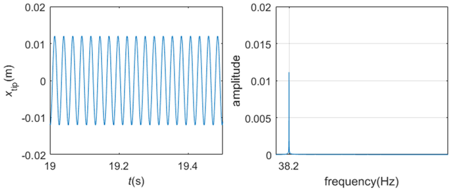
The dynamic response and frequency spectrum of the ‘blade’ tip.
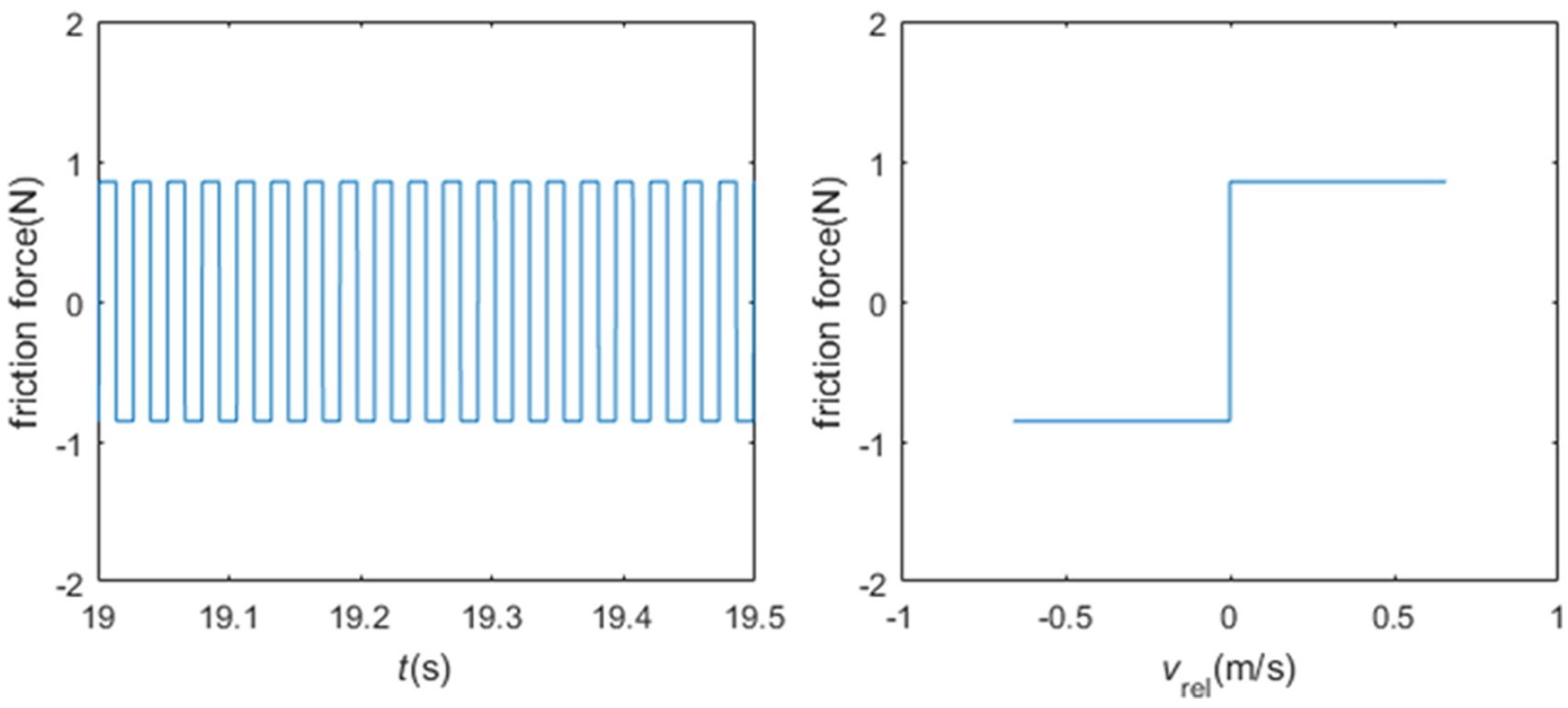
Friction force versus time and relative velocity.

The motion and frequency spectrum of the damper.
The dynamic response and frequency spectrum of the ‘blade’ tip.
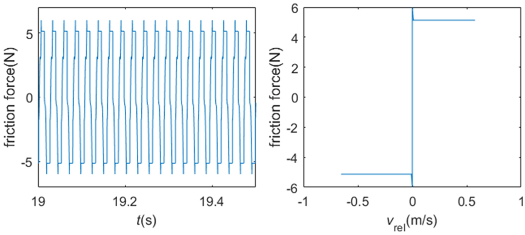
Friction force versus time and relative velocity.

The motion and frequency spectrum of the damper.

The dynamic response and power spectral density of the ‘blade’ tip.

Friction force versus time and relative velocity.

The motion and frequency spectrum of the damper.
Gross slip mode
Figures 5–7 show the results when the normal contact force N1 is 2.85 N and the external excitation force amplitude is f = 20 N. The steady-state response and frequency spectrum of the ‘blade’ tip are illustrated in Figure 5, and friction force versus time
Stick–slip mode
Figures 8–10 show the results when the normal contact force N1 is 17.1 N and the external excitation force amplitude is 20 N. Figure 8 shows the steady-state response and frequency spectrum of the ‘blade’ tip, and friction force versus time
It turns out that the motion of the damper remains periodic (Figure 10). From the frequency spectrum plot, it can be found that there are two main harmonic components of the motion of the damper, one is the excitation frequency and the other is the third-order superharmonic component of the excitation frequency, just like the previous gross slip case. What is different though is the disappearance of three frequency components (191, 267.4 and 343.8 Hz), which are the fifth-order, seventh-order and ninth-order superharmonic components of the driving frequency. During this vibration regime, the damper switches between stick and slip states. When in slip state, the friction force cycles between two constant values in the form of a rectangular wave and thus leads to the presence of the driving frequency and its third-order superharmonic component. But when in the stick state, the friction force is no longer in the form of a rectangular wave and must be found from equation (13). In fact, the proportion of stick state increases with the increase of the normal load, which leads to the disappearance of the higher order superharmonics of the driving frequency. This should be clearer in the next case – pure stick regime.
Pure stick mode
Figures 11–13 show the results when the normal contact force N1 is 22.8 N and the external excitation force amplitude is 20 N. Figure 11 displays the steady-state response and frequency spectrum of the ‘blade’ tip, friction force versus time
Discussion
The results under different normal contact forces show that the damper could experience three different schemes of motion: gross slip scheme, stick–slip scheme and pure stick scheme, as the normal contact force increases (relatively to the amplitude of excitation). The ‘blade’ tip could manifest periodic motion when the normal contact force is small, but when the normal contact force is high enough, the motion of the ‘blade’ tip could change to quasi-periodic vibration. Similarly, the motion of the damper can be periodic or quasi-periodic like the ‘blade’. Frequency spectra of the motion of the damper always show a predominant peak at the driving frequency during different schemes of motion. The odd-order superharmonic components of the driving frequency emerge during slip and stick–slip schemes, which seems like the phenomenon illustrated in Ouyang et al.
35
However, during the pure stick scheme, the first-order bending frequency of the whole system including the dampers and their cantilevers emerges, this is because they behave like one structure when the dampers stick to the horizontal beam. In the gross slip regime, the friction force alternates between two constant values of
The normal load effects on vibration reduction
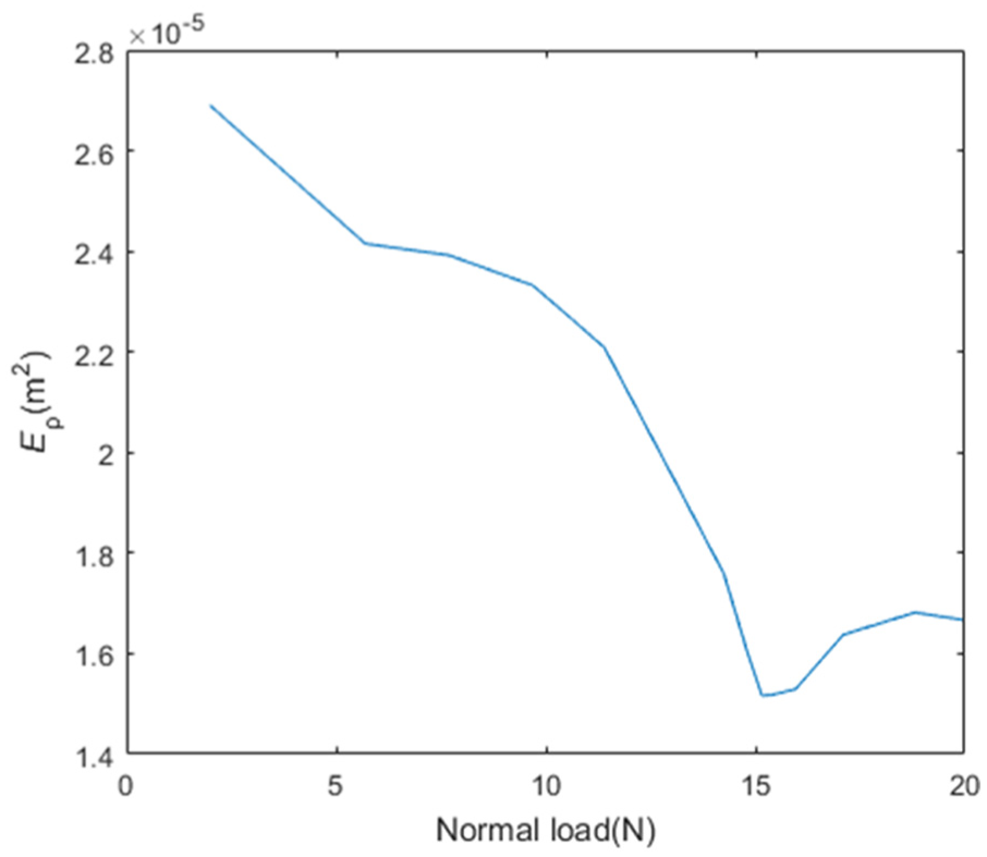
Because blade tip vibration is the most concerned quantity in aero engine vibration, it is often used as an indicator of vibration level in industry. The aim of this study is to study the effect of changing the normal contact force on the ‘blade’ tip vibration reduction. A normalised energy density (
As illustrated in Figures 14–16, with the increase of the normal contact force, the normalised energy density (

The normal load versus normalised energy density curve (f = 10 N).
The normal load versus normalised energy density curve (f = 15 N).
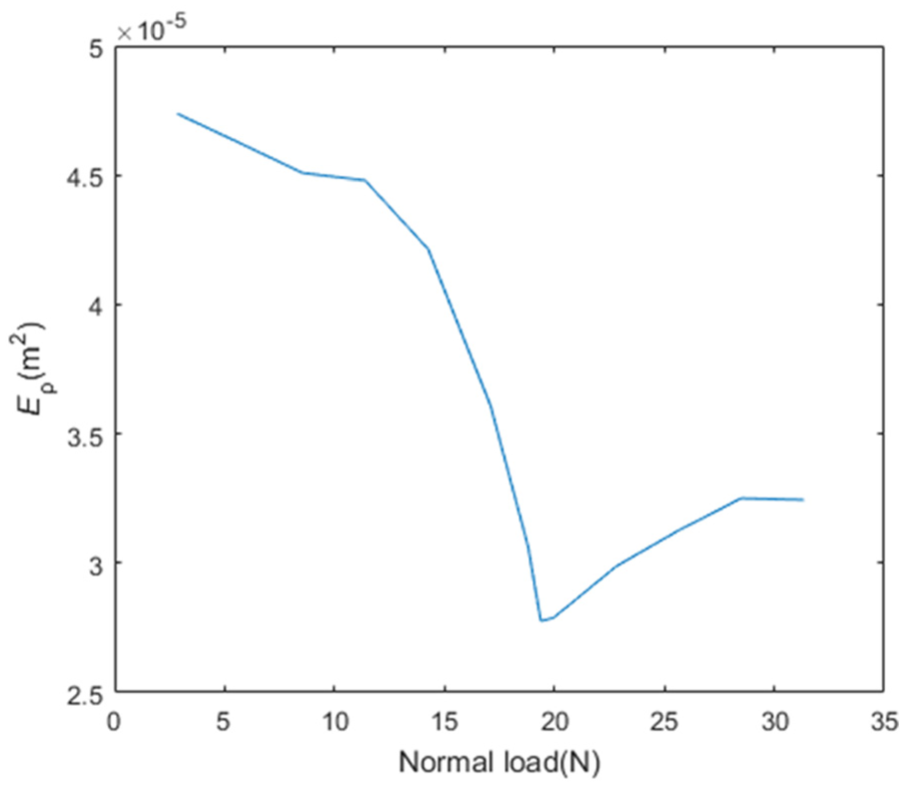
The normal load versus normalised energy density curve (f = 20 N).
This result is consistent with the previous finding that there exists an optimal mass of the under-platform damper in the aero engine that gives the best energy dissipation. It can be exploited in the design of aero engines and other structures involving friction dampers.
Conclusion
This article studies the forced vibration response of a cross-like beam structure with friction dampers. This structure may crudely represent a turbine blade with a new kind of under-platform dry friction dampers. It presents a numerical approach which uses numerical modes of the structure and is capable of accommodating the discontinuous classical Coulomb friction law.
Parametric analysis demonstrates that the damper will experience three motion regimes: gross slip regime, stick–slip regime and pure stick regime, as the normal contact force at the contact point between the damper and ‘blade platform’ increases. When the normal contact force is small, the motion of the ‘blade’ tip is periodic; however, when the normal contact force is too high, the motion of the ‘blade’ tip could change to quasi-periodic vibration. The motion of the damper is not harmonic but periodic whose period is the period of the excitation in gross slip regime and stick–slip regime, but is quasi-periodic in pure stick regime. During slip and stick–slip schemes, the odd-order superharmonic components of the driving frequency emerge because the friction force is periodic at the frequency of excitation in these two regimes. However, during pure stick scheme, the cross-like structure and the dampers form one new system, so the first-order bending frequency of the whole system takes part.
A major finding is that there is an intermediate range of the normal contact force at the damper and the ‘platform’ contact interface that results in the best vibration reduction performance under a certain condition, which confirms the similar finding from very simple structural models by a few other researchers in the past. Hence, the damper mass can be optimised in order to reduce the vibration and thus dynamic stresses of an aero engine blade to the maximum extent. The idea of this kind of dampers is believed to be applicable to other structures.
Footnotes
Acknowledgements
Much of the work was carried out during the first author’s visit to the University of Liverpool, sponsored by the China Scholarship Council. Zilin Li of Dalian University of Technology/University of Liverpool helped the coding.
Academic Editor: Elsa de Sa Caetano
Declaration of conflicting interests
The author(s) declared no potential conflicts of interest with respect to the research, authorship, and/or publication of this article.
Funding
The author(s) disclosed receipt of the following financial support for the research, authorship, and/or publication of this article: The work is supported by the National Natural Science Foundation of China (grant nos 51405452 and 11672052) and the ‘Fundamental Research Funds for the Central Universities’ (DUT16RC(3)027).