
Abstract
Chip morphology and its formation mechanisms, cutting force, cutting power, specific cutting energy, tool wear, and tool wear mechanisms at different cutting speeds of 100–3000 m/min during dry face milling of Ti-6Al-4V alloy using physical vapor deposition-(Ti,Al)N-TiN-coated cemented carbide tools were investigated. The cutting speed was linked to the chip formation process and tool failure mechanisms of the coated cemented cutting tools. Results revealed that the machined chips exhibited clear saw-tooth profile and were almost segmented at high cutting speeds, and apparent degree of saw-tooth chip morphology occurred as cutting speed increased. Abrasion in the flank face, the adhered chips on the wear surface, and even melt chips were the most typical wear forms. Complex and synergistic interactions among abrasive wear, coating delamination, adhesive wear, oxidation wear, and thermal mechanical–mechanical impacts were the main wear or failure mechanisms. As the cutting speed was very high (>2000 m/min), discontinuous or fragment chips and even melt chips were produced, but few chips can be collected because the chips easily burned under the extremely high cutting temperature. Large area flaking, extreme abrasion, and serious adhesion dominated the wear patterns, and the tool wear mechanisms were the interaction of thermal wear and mechanical wear or failure under the ultra-high frequency and strong impact thermo-mechanical loads.
Introduction
Due to the high strength-to-weight ratio maintained at elevated environment, combined with the high fracture resistance, and exceptional corrosion resistance, Ti-6Al-4V as one of the most attractive titanium alloys is extensively used for aerospace and automotive applications. However, the machining of Ti-6Al-4V titanium alloy is really a difficult task and need to be improved. If inappropriate cutting conditions were applied, nonuniform flank wear, for instance, excessive cutting edge chipping and/or flaking at the tool tip vicinity on the rake face, may occur. 1 Nowadays, the most widely used tool materials when machining titanium alloy are polycrystalline diamond (PCD)2–5 and coated cemented carbides.6–9 Moreover, the PCD tool is relatively more expensive for industry use, so the coated carbide tools are the most ideal candidate to machine titanium alloy.
Many researchers have been contributing great efforts in exploring the effective way to prolong the tool lifetime of coated tools and to achieve high efficiency during machining titanium alloy. Rao et al.10,11 found that there was little variation in the temperatures and shear stresses in the primary shear zone through the experimental and numerical investigation when face milling of Ti-6Al-4V titanium alloy with uncoated carbide tool with an abundant supply of coolant within the range of cutting speeds from 76.2 to 182.9 m/min. The specific cutting energy also exhibited no much difference, leading to no much change for the friction coefficient and cutting force. Çalışkan and Küçükköse 12 developed a new cutting tool for Ti6Al4V alloy with aCN/TiAlN coatings in face milling experiments and found that abrasion and adhesion were the main wear modes; stair-formed face wear, flank wear, chipping, and build-up edge were dominant tool failure patterns; and other types of tool failures were thermal cracking and sticking formation. Liu et al. 13 developed (nc-AlCrN)/(a-Si3N4) and (nc-AlTiN)/(a-Si3N4) coatings to machine titanium alloys with high cutting speeds, and it was found that oxidation wear and adhesive wear were the main tool wear types for the two tools in dry cutting tests. Li et al. 14 compared the cutting performance of multilayered TiAlN and AlCrN coatings on solid carbide end mills and discovered that the TiAlN was more suitable for the multilayer coating of end mill during machining Ti-6Al-4V alloy. Niu et al. 15 conducted experiments and proved that physical vapor deposition (PVD)-TiN/TiAlN insert exhibited better performance in milling TC6 alloy than chemical vapor deposition (CVD)-TiN/Al2O3/TiCN insert, and adhesion and spalling dominated the wear mechanisms. When the same coated insert was used in milling of TC11 and TC17 under dry condition, TC17 alloy was suggested to machine using PVD-(TiN/TiAlN)-coated carbide insert while CVD-(TiN/Al2O3/TiCN)-coated insert was suitable for milling TC11 alloy. 16 The synergistic interaction among adhesion of work material, coating delamination, diffusion, plastic deformation, attrition, and thermal cracks were always the coated tool wear mechanisms.1,17 However, the machining performance of coated cemented carbide tools in high speed range and even ultra-high speed range, especially for titanium alloy face milling tests, were seldom reported due to the difficulty in controlling the high cutting temperature, the possibility of burning chips, and the limited tool life.
To obtain higher cutting speed during traditional machining, a larger tool diameter of the end mill is usually applied in the high-speed machining tests.18–22 Li et al.23,24 had tried to use PCD in high- and very high–cutting speed (500–2000 m/min) milling of titanium alloy with a large diameter (125 mm) face mill equipped with the cutting width of one-fifth dimension of the tool diameter. The increase in cutting speed dramatically decreases tool life. However, as a result of the high temperature, limited tool life, and intense fire hazard, it is extremely difficult to apply higher cutting speed than 500 m/min in Ti-6Al-4V milling using the coated carbide cutting tool.25,26 As per many research works, the cemented carbide tools cannot withstand very high cutting speed even being coated by TiAlN-TiN (or other typical coating materials) due to the softening effect at high cutting temperature and the oxidation of TiN above 500°C, but it has been reported recently that the possibility of ultra-high-speed milling may be achieved with coated carbide tools in case of small depth of cuts and fairish feed rates to acquire relatively low cutting temperature rise. 27
So, in order to explore the possibility of high- and ultra-high-speed face milling of Ti-6Al-4V alloy and to investigate the cutting performance of coated cemented carbide tool under high and even ultra-high cutting speeds, the face end milling experiments of titanium alloy were carried out at small depth of cuts and a low feed rate, ensuring that these values are small enough to contribute less thermal effect at further higher cutting speed levels. The analysis of chip morphologies, chip formation mechanisms, tool wear morphologies, and tool wear mechanisms was conducted utilizing optical microscope and scanning electron microscopy (SEM) images of the chips and energy-dispersive spectroscopy (EDS) results of special location or area. These produced new analysis results and data will be of significance to practicing master engineers and help enhance the scientific comprehension of the possibility of using coated carbide tool and its cutting performance and degradation at very high cutting speeds.
Experimental procedures
Figure 1 reveals the machine tool and the cutting force measuring equipment. A DAEWOO ACE-V500 computer numerical control (CNC) vertical machine center, equipped with a 15-kW motor drive and a maximum spindle speed up to 10,000 r/min, was employed to conduct the ultra-high-speed milling tests. A 9257A Kistler-type dynamometer was utilized to measure the instantaneous force components in x, y, and z directions of the machine table, which is the cutting force Fx, the feed force Fy, and the axial force Fz, respectively. After amplified using the multichannel charge amplifier, the cutting forces were recorded down through a signal analyzer software. The same workpiece material (two-phase α + β titanium alloy Ti-6Al-4V, whose thermo-mechanical properties and chemical composition were detailed) as our former researches23–26 is chosen to facilitate comparison and make sure the continuity of investigations. And a Ti-6Al-4V alloy rectangular block with a dimension size of 30 × 75 × 50 mm3 was selected to be mounted on the dynamometer.
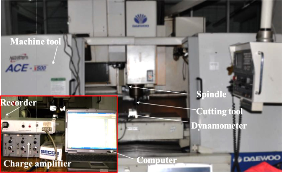
Experimental setup.
The geometry details of the tool insert and its milling cutter are exhibited in Figure 2. A face mill (made by SECO, Inc., catalog number: R220.53-0125Al-09-12CA) with a tool diameter of 125 mm, a 10° cutting rake angle, a 45° major cutting edge angle, a −5° radial rake angle, and a 20° axial rake angle was used as the cutting tool holder in the experiments. In order to avoid the effect of the tool tip run-out on tool wear and the machined surface, only one insert was fixed to the cutter. The carbide tool insert with PVD-(Ti,Al)N-TiN coatings, whose catalog number is SEEX09T3AFTN-M08, F40M, is an end milling insert in square shape with a 45° approach angle, a 3.97 mm width, a 9.525 mm cutting edge length, a 20° clearance angle, and a 0° rake angle. For materials easy to form long chips, excellent chip flow condition, with smaller radial force component compared to that of axial force, can be provided with the 45° insert approach geometry. This geometry can spread the load over the long cutting edge and provide a strong insert edge that permits faster feed rates and small axial depth of cuts to be utilized. 28

The face end mill and the mounted insert’s geometric dimensions.
Dry milling tests were performed in down milling configuration. The workpiece dimension and the cutting parameters used in the milling tests are illustrated in Figure 3. The cutting parameters utilized in the machining trials are as follows: cutting speed vc = 100, 250, 500, 1000, 1500, 2000, 2500, and 3000 m/min; a constant feed per tooth fz = 0.05 mm/z; the same radial depth of cut ae = 10 mm; and emerging the equivalent axial depth of cut ap = 0.2 mm. The feed direction is in the 30-mm direction of the rectangular block of the workpiece. And for each machining test, a new sharpen cutting tool edge was always used to ensure that the reliable results can be achieved. For the purpose of consistencies of the experimental values, experiments were repeated at least three times until reliable and stable results were obtained. The machining trials were stopped after a cutting length of 30 mm to ensure the same metal removal volume (60 mm3). The same methodology was used for all machining tests.

Illustration of workpiece dimension used in the milling tests.
The machined chips were gathered for subsequent analysis after each machining trial, bagged and labeled with a number for tracing the characteristics of the chips obtained under the corresponding cutting speed with a KEYENCE VHX-600E optical microscope made in Japan and an FEI Quanta FEG 250 SEM made in the United States equipped with an Oxford-type X-MAX50 EDS made in Britain. The collection including a thorough sweeping of milling machined surfaces among experimental trials. The width of tool flank wear bands was measured by the optical microscope, and the tool failure morphologies were captured and detected by SEM.
Results and discussion
Chip morphology and chip formation mechanisms
Morphologies of the chips at various cutting speeds are detailed in Figure 4. As displayed in this figure, the physical forms of the chips generated during milling are more dominated by the effect of cutting speed: C-type long chips (see Figure 4(a)) when the cutting speed is 100 m/min, C-type curled long chips (see Figure 4(b) and (c)) at cutting speeds of 250 and 500 m/min, straight short chips (see Figure 4(d) and (e)) at cutting speeds of 1000 and 1500 m/min, and fragmented chips (see Figure 4(f) and (g)) at cutting speeds of 2500 and 3000 m/min.
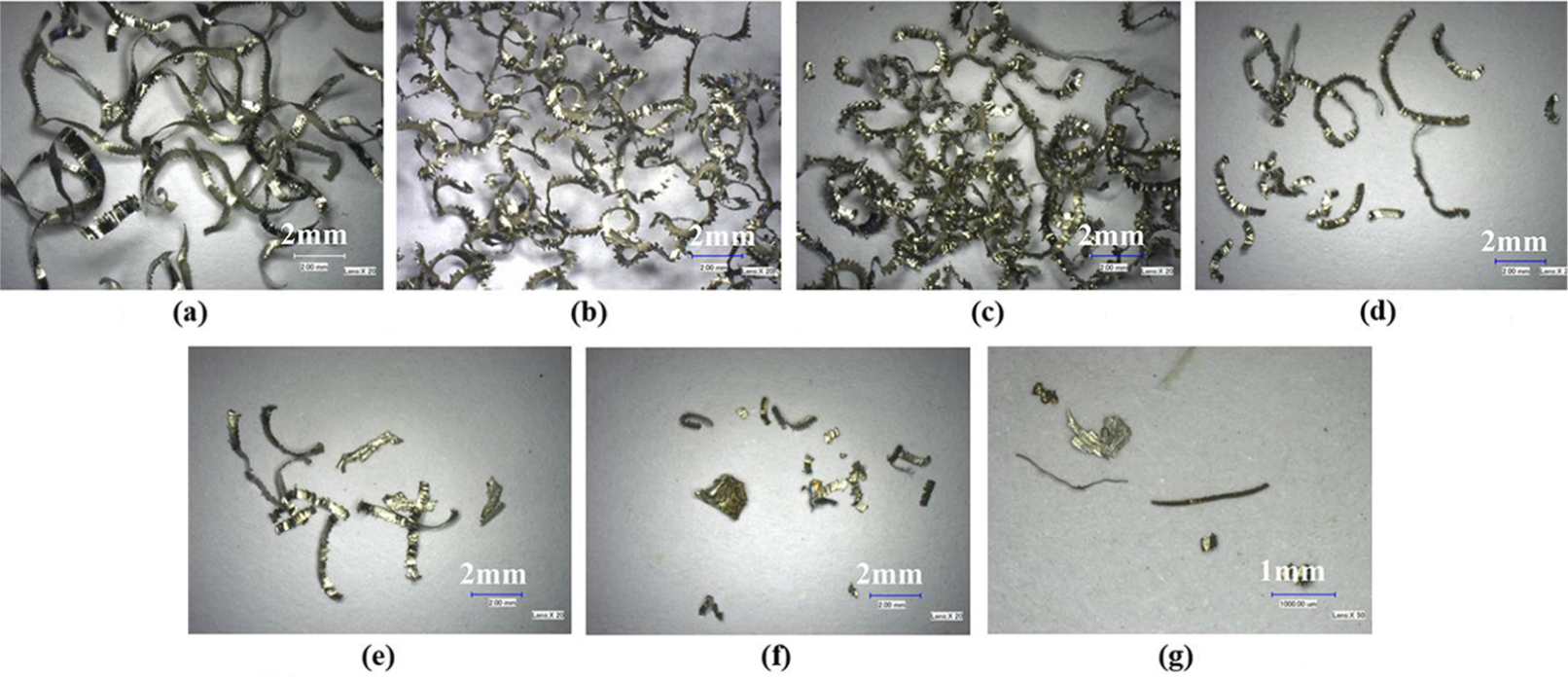
Chip morphologies under different cutting speeds: (a) vc = 100 m/min, (b) vc = 250 m/min, (c) vc = 500 m/min, (d) vc = 1000 m/min, (e) vc = 1500 m/min, (f) vc = 2500 m/min, and (g) vc = 3000 m/min.
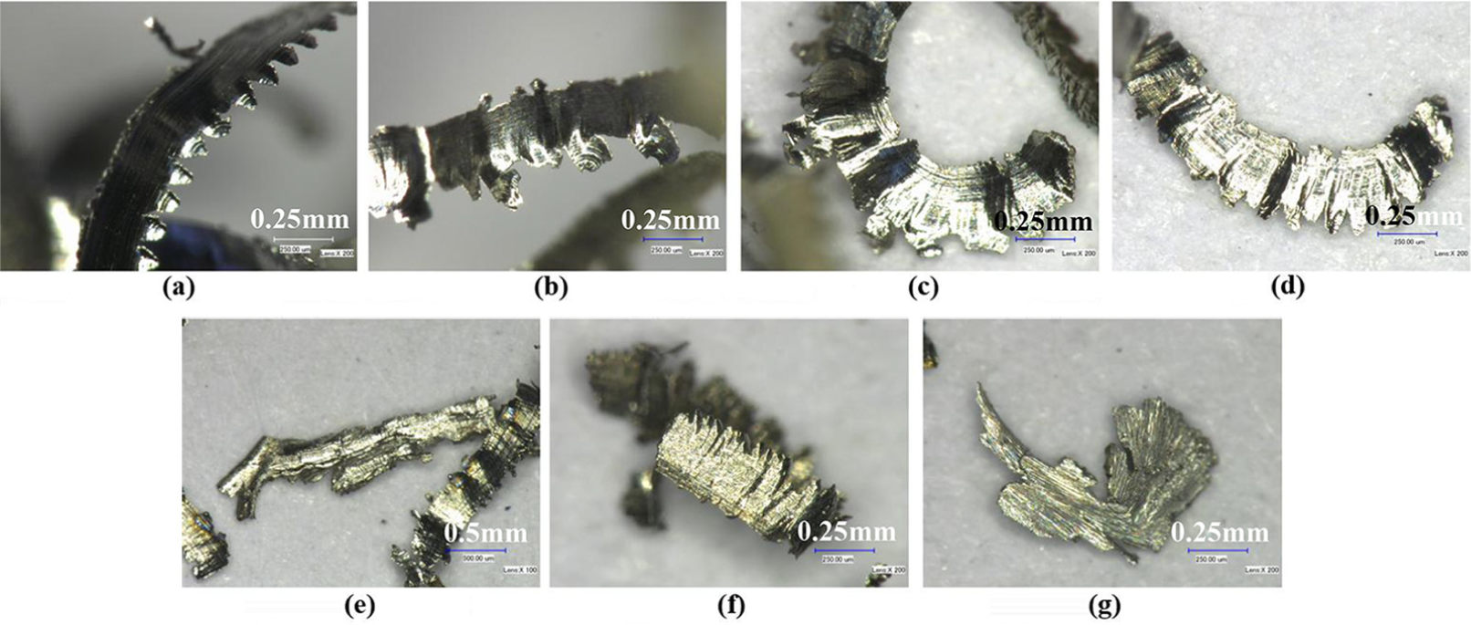
Figure 5 presents the chip-free surfaces under different cutting speeds. When the cutting speed was relatively low (100 m/min), regular shape ductile chip tearing occurred at the inner circle of the chip (see Figure 5(a)), which is the corner section taken shape by the vicinity of tool nose edge. 26 When the cutting speed increased (250 and 500 m/min), irregular shape ductile chip tearing occurred at the outer circle (see Figure 5(b) and (c)). This is attributed to the strain hardening of chip material at lower cutting speeds and thermal softening at higher cutting speeds. At lower cutting speeds, the workpiece material exhibited the brittle behavior with little effect of either strain rate or temperature. Higher cutting speeds lead to the increase in material ductility and higher cutting temperatures. When the cutting speed was further increased (>1000 m/min), the segmentation of the chips became more apparent (see Figure 5(d)–(f)). However, the cutting temperature at localized region of chips was high enough to cause the burning of thin chips. The higher the cutting speed, the more easily the chips were burned, giving rise to the difficulty in the collecting of chips. So, the chips generated at cutting speeds >1000 m/min are short and even fragmented (see Figure 4(d)–(g)). This should obviously be ascribed to the higher strain rates and temperature variation under very high cutting speeds, and the process was more complex during chip formation. Moreover, because of the prone to burn of titanium chips especially under very high cutting speeds, to reduce the likelihood of fires, in the present test, a small dimension of cut in depth (0.2 mm) was selected to ensure that the chip can burn completely in the process of generating and flying out, so that after falling, the chips would not become a source of ignition.

Free surface morphologies of chips under different cutting speeds: (a) vc = 100 m/min, (b) vc = 250 m/min, (c) vc = 500 m/min, (d) vc = 1000 m/min, (e) vc = 1500 m/min, (f) vc = 2500 m/min, and (g) vc = 3000 m/min.
The back surface of chips is usually in the secondary deformation zone during machining, and the strike-sliding friction between the tool rake face and chip, the degree of plastic deformation, and heat generation are highly dominated by the cutting speed. Figure 6 illustrates the back surface of the machined chips collected in different cutting speeds. At the cutting speed of 100 m/min, the chip back surface is a relatively shiny and smooth surface (Figure 6(a)), while the back surface of chips captured at higher cutting speeds is nearly a more uneven curved surface. This can be correlated to the brittle-to-ductile transition of the titanium alloy when cutting speed is increased to cutting speeds >100 m/min. The increase in ductility should be responsible for the uneven curved surface for the morphologies shown in Figure 6(b)–(f). However, the chip shown in Figure 6(g), to which special attention need to be paid individually, is different from the former chips.
Back surface morphologies of chips under different cutting speeds: (a) vc = 100 m/min, (b) vc = 250 m/min, (c) vc = 500 m/min, (d) vc = 1000 m/min, (e) vc = 1500 m/min, (f) vc = 2500 m/min, and (g) vc = 3000 m/min.
To evaluate the chip formation mechanisms during the milling process, the large magnification images of the chip morphologies were captured by SEM. Microstructural morphologies of the chips under the cutting speeds of 100–2500 m/min are exhibited in Figure 7. The chips have clear saw-tooth profile and are overall of segmented type under the cutting speeds delivered in this figure, and no separation phenomenon of the serrated chips along the shear zone of two jointed saw-tooth was found. Moreover, the saw-tooth pitch (the saw-to-saw distance) of the chips increases considerably as the cutting speed increases, and the degree of chip segmentation became more apparent. This tendency is attributed to the mixed modes of adiabatic shear and ductile fracture in the shear bands of chips. 29
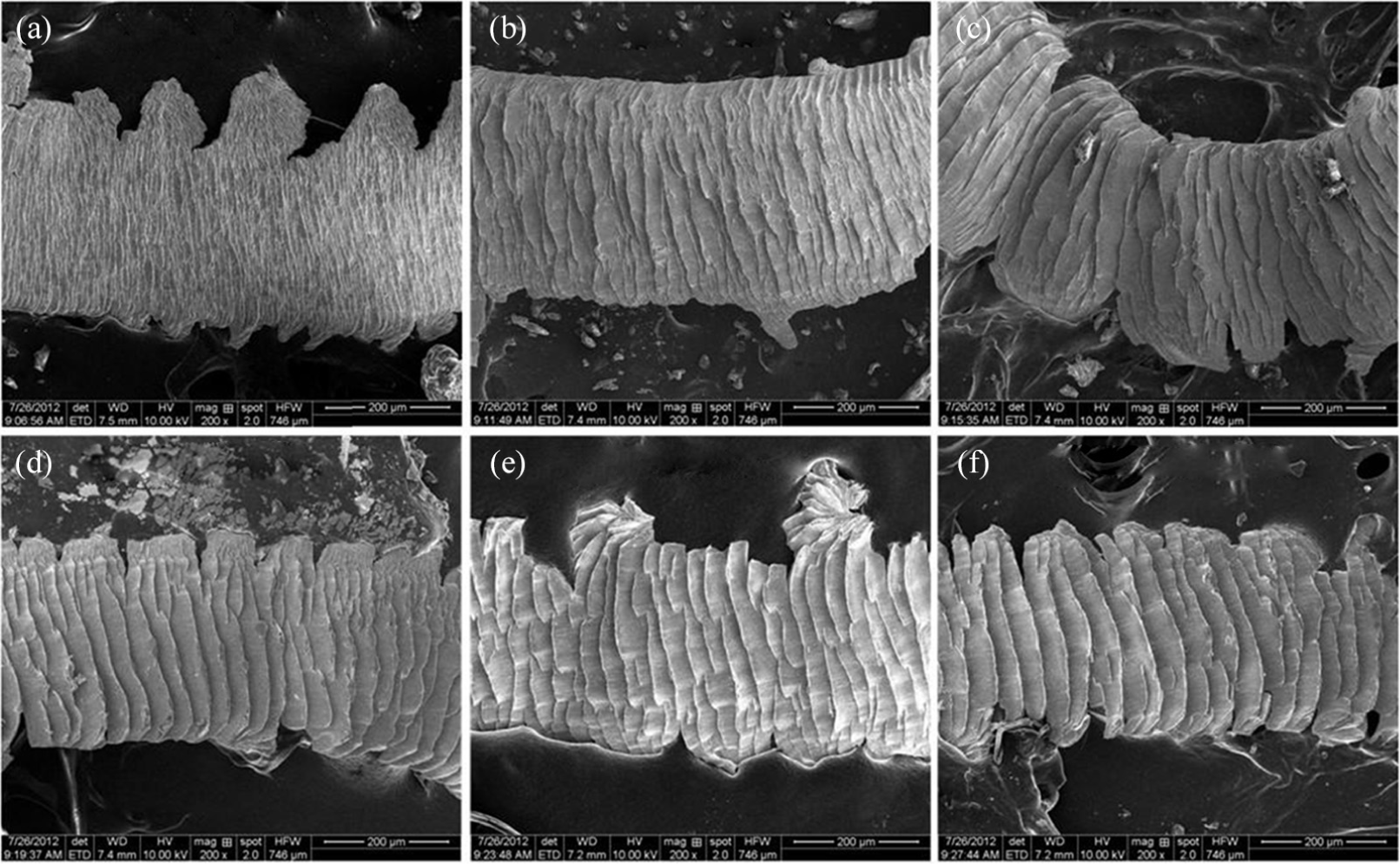
Microstructural morphologies of the chips versus cutting speed: (a) vc = 100 m/min, (b) vc = 250 m/min, (c) vc = 500 m/min, (d) vc = 1000 m/min, (e) vc = 1500 m/min, and (f) vc = 2500 m/min.
The chip obtained at 3000 m/min (see Figure 6(g)) was measured independently by SEM and EDS to evaluate the chip formation mechanism. Figure 8 details the SEM photographs of this chip and the EDS result of point 1 on the chip. As can be seen from the result, there is melted chip material on the chip back surface, and the existence of oxygen element in the melted chip reveals that the melted material was burned or oxidized under high temperature.

SEM photographs of the chip and its EDS result of point 1 on the chip (vc = 3000 m/min).
Cutting force and cutting power
The resultant cutting force (total cutting force) can be calculated by equation (1)

The cutting power desired in the milling process can be calculated by multiplying the cutting speed by the average of the total cutting force

The variation of cutting force components, resultant cutting forces, and cutting power versus cutting speed is enumerated in Figure 9. With the increase in cutting speed, all the measured maximum cutting force components Fx, Fy, and Fz exhibited a tendency of increasing (Figure 9(a)). When the cutting speed is lower than 1500 m/min, the axial force increased faster than the other two force components. However, at the cutting speed >1500 m/min, the cutting force Fx increased more rapidly, the feed force Fy was stable within a certain range, and the axial force Fz kept increasing regularly. Both the maximum and average of resultant cutting forces were increased steadily (Figure 9(b) and (c)), revealing that the mechanical loads which was applied to the cutting tool were strengthened with the increasing cutting speed. Due to the low thermal conductivity of titanium alloy, the cutting heat cannot be spread out promptly during machining, so the tool wear rates increased rapidly when the cutting speed was increased, leading to the more serious chatter of the face mill and larger obstruction of the produced fresh machined surface. When the cutting speed is very high, the cutting power during machining may approach the power limit of the machine tool (Figure 9(d)), which was not advisable for the machine tool to work for a long time under such high spindle rotation speed. It can be inferred that the instantaneous high mechanical and thermal stresses applied to the cutting tools in high-speed face milling should be responsible for the rapid tool wear.

Cutting forces versus cutting speed: (a) maximum cutting force components, (b) maximum resultant cutting force, (c) average resultant cutting force, and (d) cutting power.
Specific cutting energy
The energy consumed in the removal of a unit volume of material can be regarded as specific cutting energy. For a certain material, the specific cutting energy uc (J/mm3) can be calculated through equation (3) using trapeze integration method 30

where Fx and Fy are the cutting force components in the x and y directions (N), respectively. vc, Vrem, and tc are the cutting speed (m/min), the removed chip volume (mm3), and the cutting time (s), respectively.
The calculated specific cutting energy of Ti-6Al-4V alloy versus cutting speed in milling experiments with cutting speeds from relatively low to very high is presented in Figure 10. The specific cutting energy presents the nonlinear increase with cutting speed, and the high specific cutting energy at high cutting speed was due to the material undergoing an intense plastic deformation under high shear strain rates; consequently, an uneven stress distribution and temperature gradient is caused by the strong impact interaction of cutting tool and workpiece.
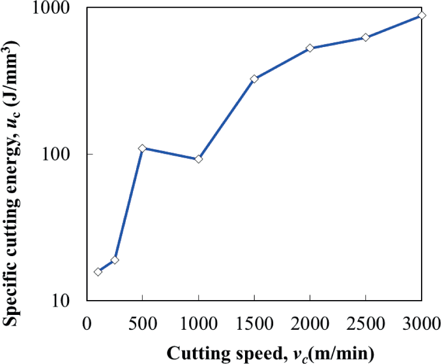
Specific cutting energy of Ti-6Al-4V alloy versus cutting speed.
Tool wear and tool wear mechanisms
Figure 11 illustrates the maximum wear bands of flank face under different cutting speeds and constant metal removal volume. It is noted that the flank wear increased rapidly when the cutting speed is increased. The cutting temperature and the tool wear rate is relatively low at lower cutting speeds (100 and 250 m/min), so the tool flank wear was small. But when the cutting speed is further increased, the tool wear rate was obviously promoted. The flank wear even reached 1.5 mm at cutting speeds >1000 m/min and nearly 3 mm at a cutting speed of 3000 m/min.

Maximum flank wear of cutting tools versus cutting speed after constant metal removal volume.
The wear conditions of the cutting tools in rake face and flank face are shown in Figure 12. As can be seen from the images, the tool failure patterns at cutting speeds 100–2000 m/min were mainly tool flank wear, while catastrophic chipping or flaking and flank wear were the typical tool failure modes at cutting speeds >2000 m/min. The cutting process was deteriorated with the increase in cutting speed in terms of the following items: the serious friction between workpiece and the tool flank face, the obvious adhesion of chips on the cutting edge along with the flank face, the rapid increase in tool flank wear bands, and the increasing possibility of chipping or flaking of cutting edge. In addition, the melt chips were observed on the cutting edge near the flank face shown in the wear images of 2000 m/min. The intensively cyclic impacts under the cutting speeds of 2500 and 3000 m/min should be responsible for the tool damage such as the catastrophic flaking or chipping of tool rake face, and also, the cutting tool cannot perform effectively in such extremely egregious condition.

Tool wear morphologies of rake face and flank face under different cutting speeds.
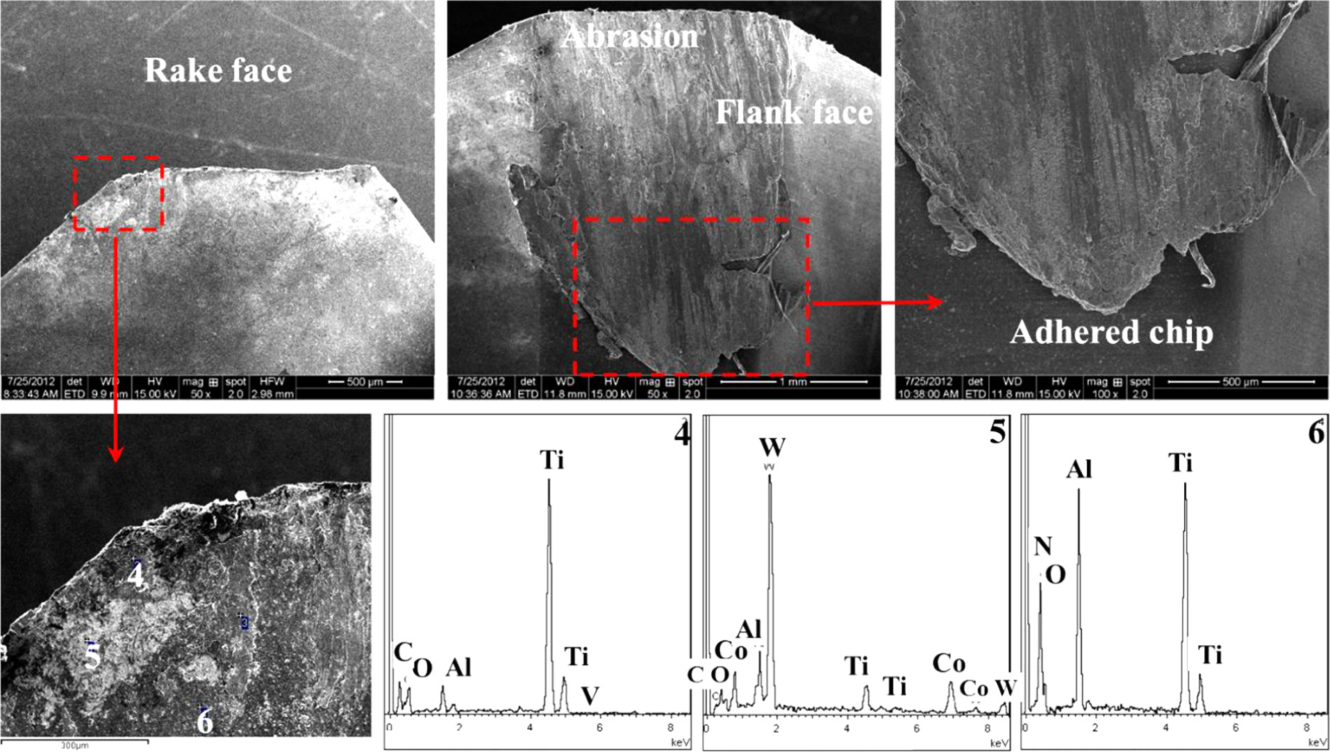
The SEM images of the failure morphologies and EDS results for coated carbide tool at cutting speeds of 250, 1000, and 2000 m/min are listed in Figures 13–15, respectively. Due to small chip–tool contact area and the poor thermal conductivity of titanium alloy during machining, high temperature was concentrated at the tool tip vicinity, and hence, the adhesion between the tool and the workpiece can easily be enhanced. Adhered chip on the cutting edge near the rake face and abrasion in the flank face were detected on the wear morphologies of the cutting tool when the cutting speed was 250 m/min (see Figure 13). EDS results of points 1, 2, and 3 in Figure 13 reveal that W, C, and Co elements from the tool substrate existed and were exposed in the tool contact zone around point 2. And the chip material at point 1, the tool substrate material at point 2, and the coating material at point 3 were oxidized under high cutting temperature and high pressure, since oxygen element was observed. The cutting temperature was increased with the increase in the cutting speed, and the tendency of chemical reactivity of titanium alloy with the cutting tool substrate and coating materials was more apparent at elevated temperatures. So, the similar oxidation wear can be observed from the EDS results of points 4, 5, and 6 shown in Figure 14 and points 7 and 8 shown in Figure 15. And the percentage of oxygen atomicity increases as the cutting speed varies from the low cutting speed to the higher cutting speeds, indicating that the oxidation wear of coated carbide tools when milling titanium alloy was more serious with the increase in cutting speed. Coating delamination at cutting edge vicinity in the rake face as shown in Figure 14, severe abrasion in the flank face, and adhered chip at the fringe of flank wear band were the main failure types of coated carbide tool at 1000 m/min cutting speed. Moreover, at a cutting speed of 2000 m/min, the adhered melt chip in the rake face and the intensive adhesion and abrasion in the flank face dominated the failure process of the coated tool.

SEM images of the failure morphologies and EDS results for coated carbide tool in face milling of titanium alloy Ti-6Al-4V at a cutting speed of 250 m/min.
SEM images of the failure morphologies and EDS results for coated carbide tool in face milling of titanium alloy Ti-6Al-4V at a cutting speed of 1000 m/min.

SEM images of the failure morphologies and EDS results for coated carbide tool in face milling of titanium alloy Ti-6Al-4V at a cutting speed of 2000 m/min.
As the cutting speed increased during machining, the cutting forces measured increased rapidly due to the larger cutting loads and cutting energy to remove the workpiece material from the substrate. And at the same time, the cutting temperature increased because of the more severe friction between the cutting edge and noncutting surface of workpiece, except for the cyclic thermal shock which would weaken the mechanical properties of cutting tool material, the tool wear accelerated sharply into the abrupt tool wear stage. The chemical reaction of elements from both the tool material and workpiece material promoted the thermal wear of cutting tool, which in turn facilitate the mechanical wear of the cutting tools. Eventually, the large tool wear bands were detected in the flank wear, and the different wear patterns mutually accelerated the process of each other. Based on the above analyses, the main failure mechanisms of coated cemented carbide tools during face titanium alloy milling at high cutting speed range were the complicated and collaborative interactions among abrasive wear, coating delamination, adhesive wear, oxidation wear, and thermal–mechanical–mechanical impacts. And the abrupt abrasive wear, the adhered chips on the wear surface, and even melt chips were the most typical wear forms in high-speed milling due to the high cutting temperature.
The SEM images of the failure morphologies for coated carbide tool in face milling of titanium alloy Ti-6Al-4V at 3000 m/min are illustrated in Figure 16. When machining titanium alloy under such high cutting speed, very high cutting zone temperature occurred, and the cutting tool was subjected to ultra-high frequency and strong impact thermal–mechanical loads. The chips burned under high cutting temperature; meanwhile, the cutting edge was submerged in the extremely hot environment, leading to the reduction of strength and hardness. The tool failed to maintain its shape integrity in a few seconds, exhibiting large area flaking in the rake face and extreme abrasive wear and serious adhesive wear in the flank face. The tool failure mechanisms at the ultra-high cutting speed range were the interaction of thermal wear and mechanical wear or failure under the ultra-high frequency and strong impact thermo-mechanical loads.

SEM images of the failure morphologies for coated carbide tool in face milling of titanium alloy Ti-6Al-4V at a cutting speed of 3000 m/min.
Conclusion
For the purpose of evaluating the machining performance of coated cemented carbide tool in ultra-high-speed face milling of titanium alloy Ti-6Al-4V, experiments at different cutting speeds ranging from 100 to 3000 m/min were conducted with small depth of cut and feed rate. The cutting speed significantly influences the machining process in terms of chip formation, cutting force, cutting power, specific cutting energy, tool wear, and tool wear mechanisms. The following conclusions can be drawn from this research:
The chip shape or geometry varied with cutting speed increasing from 100 to 3000 m/min as follows: C-type long chips → C-type curled long chips → straight short chips → fragmented chips. The cutting speed influences the friction condition of the machining process and the cutting temperature and then affects the brittleness and ductility of chip material and its mechanical properties, leading to the geometrical and morphological variation of the free surfaces and back surfaces of chips.
The chip morphologies exhibited clear saw-tooth profile and were almost segmented at cutting speeds <2500 m/min, and increasing the cutting speed resulted in the more apparent degree of saw-tooth chip morphology. However, meanwhile, the chips were prone to be burned as the cutting speed increases, leading to the difficulty in collecting of chips, and when the cutting speed overpassed 2500 m/min, discontinuous and even melt chips were obtained.
The higher cutting speeds brought in larger values of cutting forces, cutting power, and specific cutting energy in face milling of titanium alloy with ultra-high cutting speeds. And the instantaneous high thermal and mechanical stresses applied to the cutting tools in high-speed face milling should be responsible for the rapid tool wear. The high specific cutting energy at high cutting speed was ascribed to the material undergoing an intense plastic deformation under high shear strain rates, and consequently, an uneven distribution of stress and temperature gradient is caused by the strong impact interaction between cutting tool and workpiece.
The main wear mechanisms of coated cemented carbide tools were the complicated and collaborative interactions among abrasive wear, coating delamination, adhesive wear, oxidation wear, and thermo-mechanical impacts when face milling of titanium alloy at the high cutting speed range. And the abrupt abrasive wear, the adhered chips on the wear surface, and even melt chips were the most typical wear patterns in ultra-high-speed titanium alloy milling owing to the high cutting temperature. Large area flaking in the rake face and extreme abrasive wear and serious adhesive wear in the flank face are observed when the cutting speed is very high. The tool wear mechanisms were the interaction of thermal wear and mechanical wear or failure under the ultra-high frequency and strong impact thermo-mechanical loads.
Footnotes
Academic Editor: Xichun Luo
Declaration of conflicting interests
The author(s) declared no potential conflicts of interest with respect to the research, authorship, and/or publication of this article.
Funding
The author(s) disclosed receipt of the following financial support for the research, authorship, and/or publication of this article: This work was sponsored by the National Natural Science Foundation of China (51605260 and 51475273), the Foundation for the Excellent Middle-aged and Young Scientists of Shandong Province (BS2014ZZ008), and the Fundamental Research Funds of Shandong University (2014GN013). This work was also financially supported by the China Scholarship Council (CSC).