This article applies the mode-matching technique to discuss acoustic scattering of waves in flexible duct/channel at the junction of planar discontinuities. Fields across the junction are expanded in normal modes that involve discontinuities in velocities at the flanged junction. The reflected and transmitted fields are matched at interface wherein the use of generalized orthogonal properties (in case of flexible bounded ducts) enables the mode coefficients in terms of system of infinite linear algebraic equations. This system is truncated and solved numerically. The numerical experiments show that the variation of structural discontinuities along with different bounding surfaces significantly alters the reflected and transmitted powers.
There are numerous problems in the field of structural acoustics, elasticity, electromagnetic wave theory, water wave, and so on, where we deal with the propagation of waves in duct or channel.1–9 In many problems, such ducts or channels contain structural discontinuities and different bounding material properties, for instance, a silencer design, where there is a coating and the abrupt geometric changes in bounding surfaces to minimize the noise transmission. Most of these problems contain discrete spectrum of wave number in the wave field, embodying in each duct section of constant material properties. The matching of scattered fields at interface along with complete orthogonal basis thereby leads to the accurate solution of the problem.
The boundary value problems of the type governed by Helmholtz’s or Laplace equation immersed with boundary conditions of Dirichlet, Neumann, or Robin (hard, soft, or impedance) type are tractable using the mode-matching (MM) technique. In such cases, the separation of variables method allows the superposition of evanescent normal modes with unknown mode coefficients in each region of duct/channel containing constant material properties. The continuity of pressure and normal velocities across the interface and the use of usual orthogonality condition enable to recast the problem into system of infinite linear algebraic equations. Such systems are classified to be Sturm–Liouville (SL) and thereby truncation and inversion give rise to the accurate solution of the problem.
In contrast, if the problem contains complicated geometries and/or the boundary conditions involving higher order derivatives, for example, membrane or elastic plate type boundaries, the standard approach fails and in consequence the use of alternative options becomes vital.10–14 The application of generalized orthogonal properties developed recently,15,16 are until indispensable. The use of eigen-field expansion yields a dispersion relation whose roots are the corresponding eigenvalues of eigenfunctions. The sustaining eigen-sub-system in such cases appears to be non-SL in nature and can be discussed using the generalized orthogonal properties. For example, see Nawaz et al.17 and Warren et al.18 for the most recent and relevant problems where the envisaged systems emerge and have been discussed successfully via MM technique.
The underlying article is largely related to the propagation and scattering of fluid-coupled structural waves in a waveguide containing multiple step discontinuities and various bounding material properties. The intention is to consider the propagation through the elastic plate–bounded channel with different incident duct modes and to analyze the scattering of fluid-coupled structural waves at the matching interface that involve step discontinuities in bounding surfaces with a flange welded or riveted along upper bounding wall. In addition, a comparative study of elastic plate bounding inlet with hard/soft and membrane bounding outlet is made. Two inlet duct modes, the fundamental mode and the secondary mode, are considered to be the incident fields, whereas reflection and transmission amplitudes are analyzed at matching interface.
The investigation is sorted in the following direction. The model problem is presented and a few key identities are collected in section “Mathematical formulation.” In section “MM solution,” a detailed MM solution is attained while considering outlet duct as hard/soft and membrane in subsections “Hard/soft-bounded outlet duct” and “Membrane-bounded outlet duct,” respectively. The obtained solution is validated mathematically and discussed physically in section “Numerical results and discussion,” where few numerical illustrations related to power distribution, normal velocity, and pressure are presented. The principle contributions of the investigation are summarized in section “Concluding remarks.”
Mathematical formulation
Consider a rectangular infinite waveguide comprising two semi-infinite duct sections and , where the overbar quantities represent the dimensional setting of coordinates. The lower surface of the duct sections lying at is acoustically rigid, whereas the upper boundary aligned along , is an elastic plate while acoustically rigid or soft or membrane wall at . A vertical step discontinuity connects the lower surfaces of these duct sections at , , while the upper boundaries are joined by means of flanged strip at , . The properties on each side of the strip are chosen to be acoustically rigid and soft at and , respectively. The geometrical configuration of the duct is shown in Figure 1.
The geometrical configuration of the problem.
The interior region of the waveguide is filled with compressible fluid of density and sound speed , whereas the exterior region is assumed to be in vacuo. The transient fluid velocity potential in two duct sections can be expressed as
Assuming the harmonic time dependence of , in which is the frequency pulsation with wave number and non-dimensionalizing the problem with respect to the length scale and time scale , the time-independent dimensionless fluid velocity potential in two duct sections satisfies the Helmholtz’s equation
At , the lower surfaces can be expressed as
The upper elastic plate condition is described by
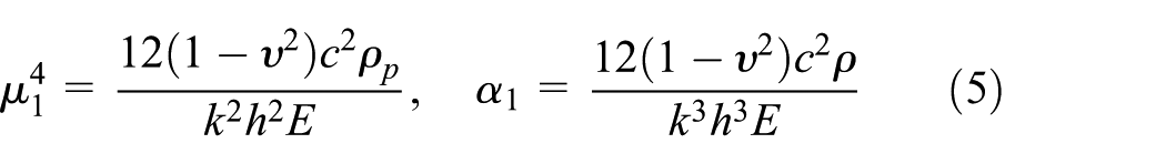
where the non-dimensional parameters is the in vacuo plate wave number and a fluid loading parameter defined by
where is the Young’s modulus with small thickness , is the density of the plate, and is the Poisson’s ratio. The properties of upper boundary of the duct lying at are assumed to be (1) the rigid/soft boundary and (2) the membrane boundary which will be defined in subsections “Hard/soft-bounded outlet duct” and “Membrane-bounded outlet duct,” respectively.
Now, at the matching interface, (coined as aperture), the fluid pressure and the normal component of velocity are continuous, while at , the vertical step discontinuities and the flange junction are taken to be rigid and soft, respectively. Thus, we summarized it as
and
In addition, the edge conditions will be applied at the end of semi-infinite flexible wall to ensure the uniqueness of the solution. Here, we impose two edge conditions at the corner of the semi-infinite elastic plate. These are zero-displacement and zero-gradient conditions which describe that how the elastic plate and vertical surface are connected with each other. The choice of edge conditions can significantly alter the scattered field. We refer to the literature19–21 for a comprehensive list of appropriate edge conditions. In the sequel, we choose clamped edge conditions, which are
and
The next section is dedicated to MM solution.
MM solution
Assuming a time-harmonic incident wave of an arbitrary duct mode is propagating from negative toward . At , it will scatter into an infinite number of reflected modes and transmitted modes. The eigenfunction expansion insets for scattered velocity potential in duct regions is
and
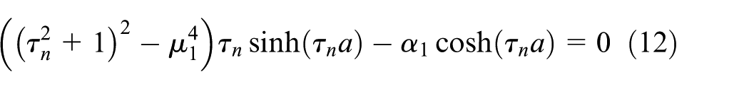
where the first term in equation (10) denotes the incident field. The quantity (where will be defined later) is chosen to scale the incident power at unity. The counter is chosen here to incorporate the fundamental mode incident () and the secondary mode incident . Substituting equations (10) and (11) into equations (2)–(4), it is found that the eigenfunctions and wave numbers can be defined in terms of eigenvalues, , wherein the eigenvalues satisfy the dispersion relation
These roots can be found numerically which in turn satisfy certain properties detailed by Lawrie.11 Obviously, such eigen-systems are non-SL in nature but contain well-defined generalized orthogonal properties as mentioned in earlier studies.15,16 Thus, for elastic plate–bounded duct, the generalized form of orthogonality relation (OR) is
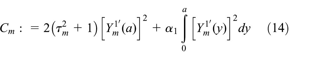
where
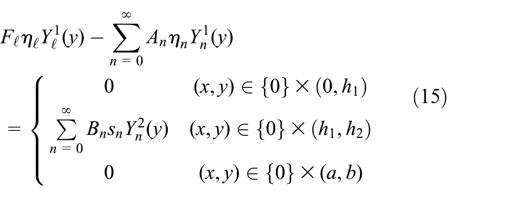
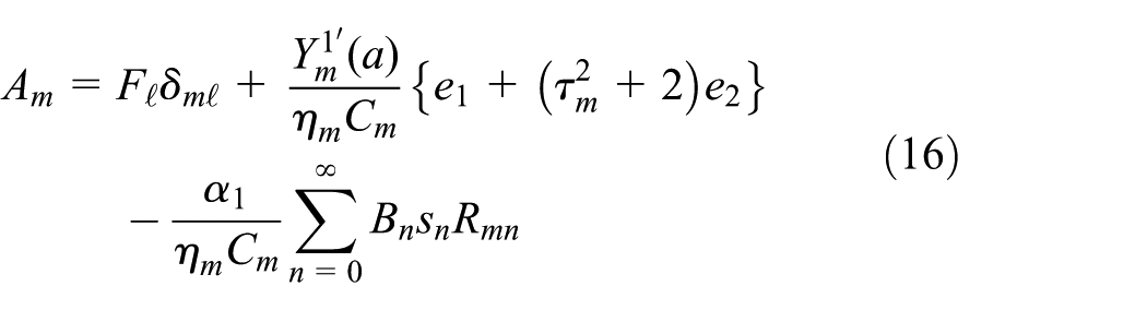
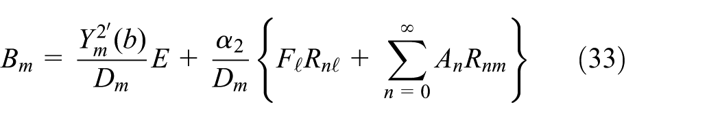
where is the Kronecker delta function. With the aid of these generalized orthogonal properties, the unknown reflected and transmitted mode coefficients can be obtained using continuity conditions along with appropriate edge conditions. Thus, substituting equations (10) and (11) into equation (6), it is straightforward to write
On multiplying with , integrating from to , and then using OR (13), it is found that
where
and
where are constants that can be found using the edge conditions (8) and (9). For this, we multiply equation (16) with , take summation over from to , and then use edge condition (8) to get
where
But from condition (9), we note that and thus can be computed explicitly from equation (20). In this way, the reflected mode coefficient is defined in the terms of transmitted mode coefficient.
Similarly, the transmitted mode coefficients can be defined in terms of reflected mode coefficient. However, for the analysis purpose, the material properties of the surface at , are chosen to be different and are discussed in following two cases.
Hard/soft-bounded outlet duct
The rigid bounding surface is given by the conditions
whereas the soft surface is defined as
Substituting the eigen-field expansion (11) into equations (22) and (23) along with equation (3), we get the eigenfunctions and wave numbers , where . Here, be the eigenvalues and for rigid upper boundary, it satisfy
while for soft upper wall, these are given by
Note that the eigenfunctions for rigid and soft bounding ducts are orthogonal in nature and usual orthogonality conditions lead to accurate solution of the problem. Thus, using the continuity condition of pressure (7) along with the standard OR, the transmitted mode coefficient can be written in terms of reflected mode coefficient as
where when and otherwise. In this way, equation (16) together with equation (26) leads to an infinite system of linear algebraic equations which can be solved simultaneously for unknowns , in each case of rigid- or soft-bounded duct.
Membrane-bounded outlet duct
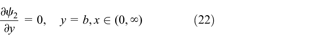
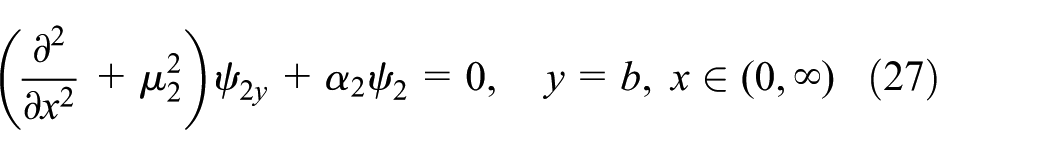
The upper membrane boundary condition is given by
where the non-dimensional parameters and are the (in vacuo) membrane wave number and the (in vacuo) fluid loading parameter, respectively, which are defined as
In the above equation, denotes the membrane tension per unit length (in the normal direction) and denotes the speed of waves (in vacuo) on the membrane where is the membrane mass per unit area. As mentioned earlier, to ensure the uniqueness of the solution, an extra edge condition is imposed at . The choice of zero displacement at semi-infinite membrane edge is given as
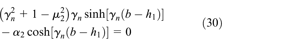
Substituting the eigen-field expansion (11) into equations (27) and (29) along with equation (3), we get the eigenfunctions and the wave numbers , for . The eigenvalues are the roots of dispersion relation
These roots can be found numerically and satisfy the properties stated by Lawrie.11 The underlying eigen-systems are non-SL in nature, and their eigenfunctions satisfy the generalized OR outlined in the work by Lawrie and colleagues10,15,16
where
Now, using the continuity condition of pressure (7) along with the generalized OR (31) and following the procedure adopted in section “Mathematical formulation” to determine the reflected mode coefficient , the transmitted mode coefficient can be calculated as
where
Note that using the edge condition (29), it is straightforward to write . Thus, we get infinite system of linear algebraic equations (16) and (33) which are truncated and solved simultaneously for unknowns (, .
Numerical results and discussion
In this section, the aforementioned systems are solved numerically after their truncation at terms. Such systems are non-SL in nature and converge suitably for the membrane and elastic plate–bounded ducts.10,18 Now, the truncated solution may be used to check the accuracy of presented algebra and distribution of energy flux. This not only validates the proposed solution but also provides an useful physical information about the boundary value problem. The conserved power or energy flux identity7,10,17,18 is given by
where indicates the incident power which incorporates both the structure-borne mode incident and the fluid-borne mode incident. Also, the choice of forcing assists to scale it at unity, whereas the reflected power () is given by
and the transmitted power ( for rigid/soft-bounded duct is
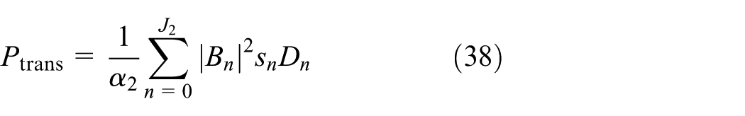
But for the membrane-bounded duct, the transmitted power is
where denotes the number of cut-on duct modes propagating in left/right duct sections. Note that the above expressions of scattered power fit in to incorporate both the fundamental mode incident and secondary mode incident.
While carrying out the parametric investigation, the speed of sound in air and density of air are taken from the work by Kaye and Laby.22 For each graph presented in this section, the inlet duct contains elastic plate of aluminum of thickness and density . The values of Poisson’s ratio and Young’s modulus are taken to be and . The outlet duct comprises membrane of mass density and tension . The other parameters chosen for analysis may vary from one case to another and thus will be stated with reference in each case.
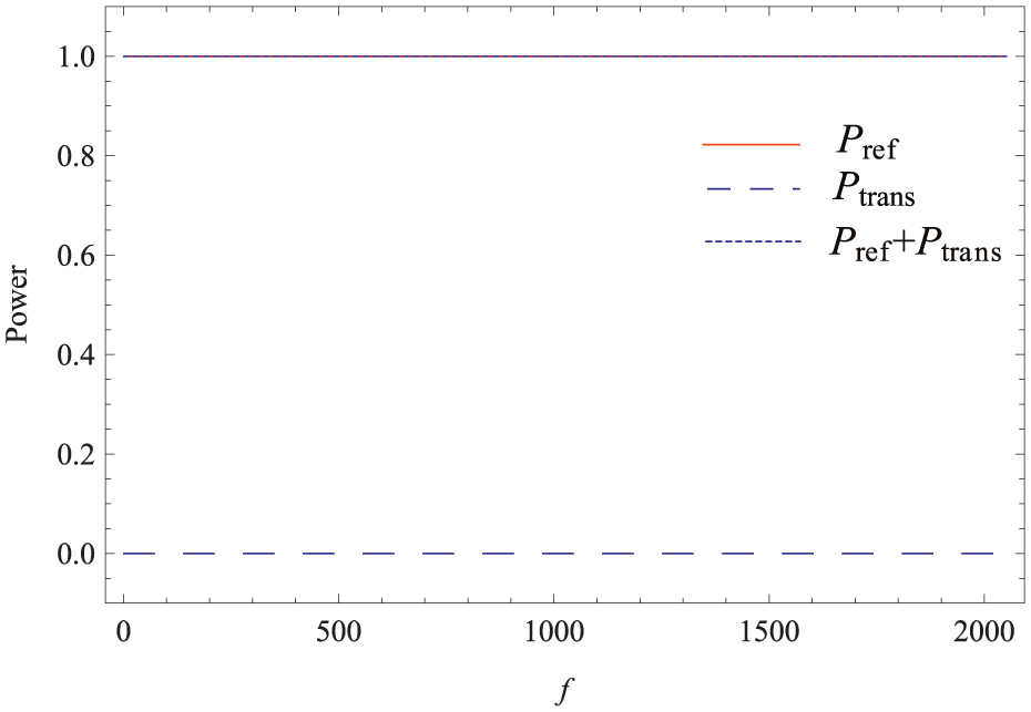
On fixing , and , the scattered powers are plotted against frequency regime (Hz). By considering the fundamental mode incident () with membrane bounding surfaces at , , almost all the incident power goes on reflection (see Figure 2). Note that in Figure 2, only the results of membrane surface at are displayed, whereas the results of rigid or soft surface are omitted due to quite similar behavior.
Power distribution versus frequency (Hz) for structure-borne mode incident () and membrane outlet.
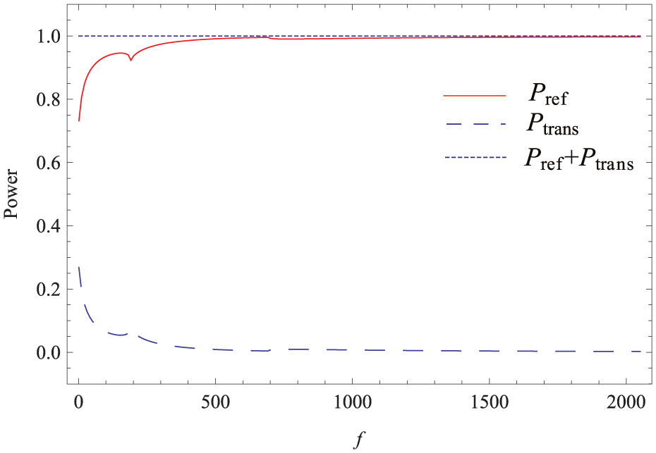
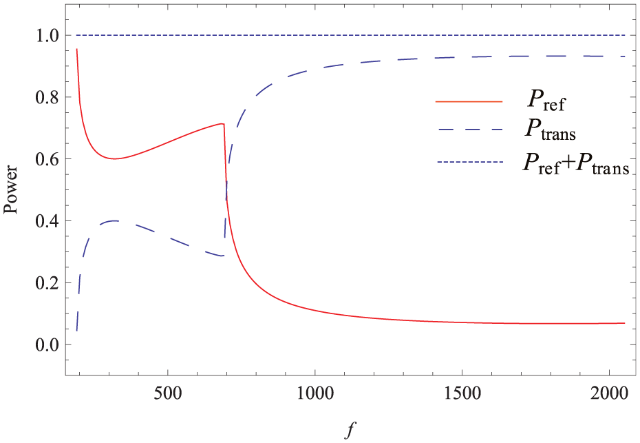
However, for the secondary mode incident (), the scattering energy flux varies on changing the material properties of bounding surface at . Note that the incident fluid-borne mode is cut-on at ; therefore, while using it as incident field, the scattered powers are plotted against frequency for Now, it can be seen that for the rigid surface at , , the reflected power decreases with an increase in the frequency (see Figure 3). But in Figures 4 and 5, such variations begin after or with soft or membrane surface at . In fact, these are the points after which the soft or membrane-bounded duct starts propagating.
Power distribution versus frequency (Hz) for fluid-borne mode incident () and acoustically rigid outlet.
Power distribution versus frequency (Hz) for fluid-borne mode incident () and acoustically soft outlet.
Power distribution versus frequency (Hz) for fluid-borne mode incident () and membrane outlet.
Now, on setting , we get the configuration of duct without flange discontinuity. For the selected setting, the power components against frequency are shown in Figures 6–9. Clearly, for structure borne-mode incident, almost all the incident power goes on reflection while excluding flange discontinuity with rigid, soft, or membrane surface at , (see Figure 6). This case is quite similar to the previously taken case discussed in the presence of flanged discontinuity. However, for the secondary mode incident, the transmission rate of energy flux increases with an increase in the frequency and is comparatively higher to the flanged junction (see Figures 7–9).
Power distribution versus frequency (Hz) for structure-borne mode incident () and membrane outlet, with no flange.
Power distribution versus frequency (Hz) for fluid-borne mode incident () and rigid outlet, with no flange.
Power distribution versus frequency (Hz) for fluid-borne mode incident () and soft outlet, with no flange.
Power distribution versus frequency (Hz) for fluid-borne mode incident () and membrane outlet, with no flange.
Now, we discuss the case containing only one step discontinuity by setting . Figures 10–16 depict the distribution of power for fundamental and secondary mode incidences in frequency regime. Clearly, for this configuration, the scattering power infers a contrary behavior to the previously discussed cases. It is interesting to note that there is a complete reflection of incident power with soft-bounded outlet for both fundamental and secondary mode incidences (see Figures 11 and 14). However, for hard and membrane-bounded outlets, the distribution of power behaves inversely for structure and fluid-borne mode incidences (see Figures 10–16).
Power distribution versus frequency (Hz) for structure-borne mode incident () and rigid outlet, with no flange and no upper step discontinuity.
Power distribution versus frequency (Hz) for structure-borne mode incident () and soft outlet, with no flange and no upper step discontinuity.
Power distribution versus frequency (Hz) for structure-borne mode incident () and membrane outlet, with no flange and no upper step discontinuity.
Power distribution versus frequency (Hz) for fluid-borne mode incident () and rigid outlet, with no flange and no upper step discontinuity.
Power distribution versus frequency (Hz) for fluid-borne mode incident () and soft outlet, with no flange and no upper step discontinuity.
Power distribution versus frequency (Hz) for fluid-borne mode incident () and membrane outlet, with no flange and no upper step discontinuity.
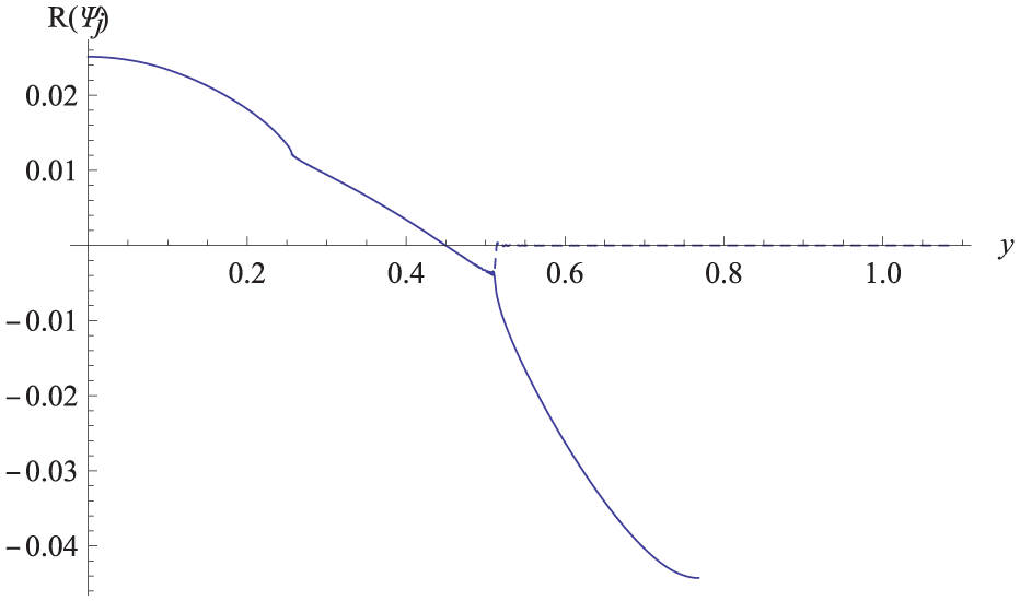
The real part of normal velocity versus duct height, (solid curve) and (dashed curve).
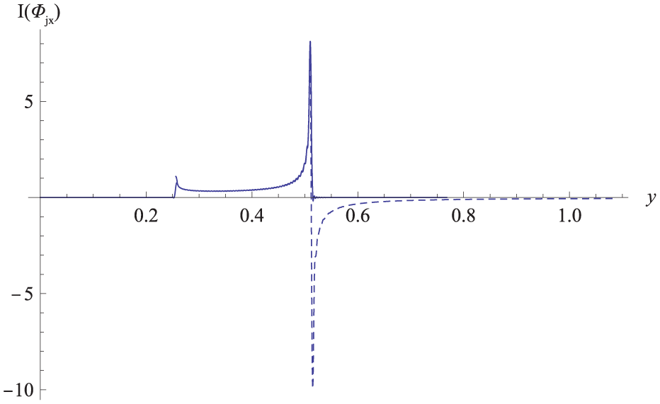
Furthermore, we may reconstruct the continuity conditions (6) and (7) at matching interface to validate the truncated solution. On taking , and and assuming the fundamental mode incident, the real (ℜ) and imaginary (ℑ) parts of non-dimensional normal velocity along with membrane surface at , are plotted in Figures 16–19. It can be seen that in the region , the real and imaginary parts of normal velocities and match exactly with and when .
The imaginary part of normal velocity versus duct height, (solid curve) and (dashed curve).
The real part of normal velocity versus duct height, (solid curve) and (dashed curve) after using Lanczos filters.
The imaginary part of normal velocity versus duct height, (solid curve) and (dashed curve) after using Lanczos filters.
However, there occur periodic oscillations in normal velocity curves around the edges. This is due to the Gibbs phenomenon23 which usually occurs in poorly convergent series near the singular point and which addressed quite well by Nawaz and collegues.10,17 To remove these oscillations and smoothen the curves, we determine Lanczos filter while opting the procedure outlined by Nawaz and Lawrie,10 Duchon,24 and Vandeven25 and reconstructing the velocity field. That is
and
where . Now, from Figures 18 and 19, the matching condition (6) is satisfied exactly.
Similarly, in Figures 20 and 21, the real and imaginary parts of pressures and are plotted. Note that and coincide as while and become zero as which is exactly stated in equation (7).
The real part of pressure versus duct height, (solid curve) and (dashed curve).
The imaginary part of pressure versus duct height, (solid curve) and (dashed curve).
Concluding remarks
The acoustic scattering problems in flexible duct involving step discontinuity have been examined. This work can be seen as a continuation of the studies made by Nawaz and Lawrie,10 Nawaz et al.,17 and Warren et al.18 and has been investigated in the following perspectives:
The inclusion of various step discontinuities together with a flange at matching interface with/without wave-bearing boundaries;
The comparative MM analysis of the structure while considering outlet duct as membrane, rigid, and soft;
Consideration of fundamental mode as well as secondary mode incidence for all the situations;
The physical insight and the validation of MM solution using the numerical results.
Through a series of numerical experiments, it has been observed that the change in outlet bounding surfaces and the variation of step discontinuities greatly affect the distribution of power in duct regions. Also, it is important to note that the distribution of power or energy flux varies inversely with the change in incident duct modes. Moreover, the cut-on point for the fluid-borne mode incident is (i.e. the point where elastic plate–bounded inlet starts propagating), whereas for this mode incident, the propagation takes place in membrane and soft-bounded outlet at and , respectively, where . However, for (the setting with no flange and no upper step discontinuity), the soft outlet yields total reflection with no transmission for both the structure and fluid-borne mode incidences.
Furthermore, the presented solution has been validated numerically through the satisfaction of matching conditions and the conserved power identity (35). However, due to the Gibbs phenomenon, there occur periodic oscillations in normal velocity curves around the edges which have been removed successfully using the Lanczos filters. Thus, the constructed solution satisfies the proposed boundary value problem. In addition, the conserved power identity (35) holds for each duct configuration. In this way, the solution is validated altogether mathematically and physically.
Footnotes
Academic Editor: Pietro Scandura
Declaration of conflicting interests
The author(s) declared no potential conflicts of interest with respect to the research, authorship, and/or publication of this article.
Funding
The author(s) received no financial support for the research, authorship, and/or publication of this article.
References
1.
PorterREvansDV. Scattering of flexural waves by multiple narrow cracks in ice sheets floating on water. Wave Motion2006; 43: 425–443.
KanoriaMDolaiDPMandalBN. Water-wave scattering by thick vertical barriers. J Eng Math1999; 35: 361–384.
9.
LawrieJBKaplunovJ. Edge waves and resonance on elastic structures: an overview. Math Mech Solids2012; 17: 4–16.
10.
NawazRLawrieJB. Scattering of a fluid-structure coupled wave at a flanged junction between two flexible waveguides. J Acoust Soc Am2013; 134: 1939–1949.
11.
LawrieJB. On eigenfunction expansions associated with wave propagation along ducts with wave-bearing boundaries. IMA J Appl Math2007; 72: 376–394.
12.
BaoGZhangW. An improved mode-matching method for large cavities. IEEE Antenn Wirel Pr2005; 4: 393–396.
13.
KirbyRLawrieJB. A point collocation approach to modelling large dissipative silencers. J Sound Vib2005; 286: 313–339.
14.
LawrieJBKirbyR. Mode-matching without root finding: application to a dissipative silencer. J Acoust Soc Am2006; 119: 2050–2061.
15.
LawrieJBAbrahamsID. An orthogonality condition for a class of problem with high order boundary conditions, applications in sound/structure interaction. Q J Mech Appl Math1999; 52: 161–181.
16.
LawrieJB. Comments on a class of orthogonality relations relevant to fluid-structure interaction. Meccanica2012; 47: 783–788.
17.
NawazRAfzalMAyubM. Acoustic propagation in two-dimensional waveguide for membrane bounded ducts. Comm Nonlinear Sci Numer Simulat2015; 20: 421–433.
18.
WarrenDPLawrieJBMohamedMI. Acoustic scattering in waveguides with discontinuities in geometry and material property. Wave Motion2002; 36: 119–142.
19.
Brazier-SmithPR. The acoustic properties of two co-planar half-plane plates. Proc R Soc A1987; 409: 115–139.
20.
NorrisANWickhamGR. Acoustic diffraction from the junction of two flat plates. Proc R Soc A1995; 451: 631–655.
21.
LawrieJBAbrahamsID. Scattering of fluid loaded elastic plate waves at the vertex of a wedge of arbitrary angle I: analytic solution. IMA J Appl Math1997; 59: 1–23.
22.
KayeGWLabyTH. Tables of physical and chemical constants. 15th ed.Essex: Longman Scientific & Technical, 1986.
23.
GottliebDShuC-W. On the Gibb’s phenomenon and its resolution. SIAM Rev1997; 39: 644–668.
24.
DuchonCE. Lanczos filtering in one and two dimensions. J Appl Meteorol1979; 18: 1016–1022.
25.
VandevenH. Family of spectral filters for discontinuous problems. J Sci Comput1991; 8: 159–192.