
Abstract
Pure electric vehicles, as a promising alternative to conventional fossil fuel–powered passenger vehicles, provide outstanding overall energy-utilizing efficiency by omitting the internal combustion engine. However, because of lower energy density in battery energy storage, the driving range per charge is limited by this electrochemical power source, leading to a so-called range phobia and presenting a major barrier for large-scale commercialization. The widely adopted single-reduction gear in pure electric vehicles typically do not achieve the diverse range of functional needs that are present in multi-speed conventional vehicles, most notably acceleration performance and top speed requirements. Consequently, special-designed multi-speed pure electric vehicle–powertrains have been compared and investigated for these applications in this article. Through the optimizing of multiple gear ratios and creating special shifting strategies, a more diverse range of functional needs is realized without increasing the practical size of the electric motor and battery. This article investigates the performance improvements of pure electric vehicle realized through utilization of multi-speed dual-clutch transmissions and continuously variable transmissions. Results reveal that there can be significant benefits attained for pure electric vehicles through multi-speed transmissions. Simulation results shows that continuously variable transmission and two-speed transmission are the two most promising transmissions for pure electric vehicle in different classes, respectively.
Keywords
Introduction
Despite the long-term benefits of pure electric vehicles (PEVs) to customers and environment, the initial cost and unsatisfactory driving range per charge present significant barriers for its large-scale commercialization. Since a breakthrough for battery technology in terms of specific energy, is not likely to occur very soon, it is necessary to pursue every possible avenue to improve powertrain efficiency.
The ideas of implementing various multi-speed transmissions to PEV to lift the average working efficiency of motor and improve the driving capability have been proposed by academic and industry in recent years.1,2 An redesigned two-speed automatic transmission was applied to an electric commercial truck 3 to improve dynamic and economic performances. The effects of integrating a two-speed automated manual transmission (AMT) to PEVs and another similar system was integrated in an electric bus.4–6 Ren et al. 7 showed a brief comparison of 1–4 speeds PEV, which adopted several subjective ratios and unrealistic shifting algorithms. Being different from the internal combustion engine (ICE)-based conventional vehicle, torque converter may be not needed in PEV since electric machine (EM) does not require minimum rotational speed. However, the torque interruption is nearly inevitable for stepped transmission, no matter it is clutch-based dual-clutch transmission (DCT) 8 or planetary-based automatic transmission (AT). 9 Compared to stepped transmissions, continuously variable transmissions (CVTs) can change gear ratios without power interruption and the infinite ratios (in the given interval) helps multi-speed PEV running smoothly similar to single-speed PEVs. For example, an infinitely variable transmission was proposed by Bottiglione et al. 10 to reduce energy consumption for PEV. According to our previous research, a comparative study of energy consumption and costs of alternative PEV transmissions, both two-speed DCT and simplified CVT can improve the overall powertrain efficiency, save battery energy, and reduce customer costs. 6
Although aforementioned studies have evaluated the economy of PEVs with some specific multi-speed transmissions, the investigation about the most suitable transmission type, speed number for various vehicle classes, that is, from B-Class to E-Class, and their relevant shifting strategies are still omitted. Therefore, following questions are arisen:
Which type of transmission has the greatest potential to improve energy efficiency for different vehicle classes?
How many speeds the transmission needs considering the dynamic and economic requirements?
What’s the shifting schedules for each of the proposed multi-speed transmission?
In this article, following limitations to most previous studies will be discussed in detail:
Powertrain structure analysis of multi-speed DCT and CVT;
Ratios and shifting schedules design for specific motor-based CVT and DCT;
Potential cost and benefit analysis in efficiency loss, driving range extension, energy consumption reduction, and manufacturing cost.
Alternative transmission configurations
Summary of vehicle configurations
Simulations are carried out to compare the alternative platforms, this section summarizes the simulation parameters of each configuration. For this article, two extremes of vehicle class are evaluated. At the small end of the size spectrum, there is the B-Class platform, often referred to as Superminis. The large vehicle platform that will be studied in this article is the executive sedan or E-Class vehicle. Vehicle characteristics are noted in the following sections.
B-class PEV configuration
The B-class car covers the Supermini/Subcompact/City/Small car segment of the automotive passenger vehicle market. They comprise approximately 30% of vehicle sales in Australia 11 (FCIA 2014) depending on where the exact divisions are made between classes. It should be noted that the nominal vehicle mass is shown below, variations for additional transmission ratios in the summary, but are included in simulations.
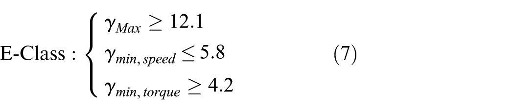
E-class PEV configuration
The E-class car covers the Executive/Large/Full size car segment of automotive passenger vehicles. They comprise approximately 6% of vehicle sales in Australia. 11 These are significantly larger than B-class vehicles and may represent the other end of passenger vehicle market in terms of vehicles size. Vehicle specifications are summarized in Table 1.
Vehicle specifications and target performance.

Motor power rating
The acceleration performance, maximum speed, and gradeability are three factors widely used to evaluate vehicle’s performance. In PEV drivetrain, appropriate motor power and transmission specifications are the essential considerations to meet the requirement of design specification. Specifically, the speed–torque (power) characteristics of propelling motor are taken as the most important parameter to be relied on. The ratio of motor maximum rotational speed to its base speed is used to represent the general performance of motor, also known as extended-speed range.
Regarding passenger cars, acceleration time is more important than maximum cruising speed and gradeability, since acceleration dictates the motor power, rather than the top cruising speed or the gradeability. The total tractive power for accelerating the vehicle from zero to speed

Although a greater speed ratio of EM will reduce the motor power rating requirement and improve vehicular dynamic performance,13,14 especially for initial accelerating, they are set 2.5 and 312,15,16 for B- and E-Class vehicles, respectively, in this study to achieve a trade-off of vehicular dynamic performance and motor cost, which is mainly determined by motor type and control strategy. The efficiency map of motors are shown in Figure 1 by red and blue curves, respectively.

Motor efficiency map (red: B-Class; blue: E-Class).
Single-speed PEV
Single-speed powertrain (Figure 2(a)) is overwhelming dominant in current PEV market, including BMW i3, Mitsubishi i-MIEV, Nissan Leaf, and all Tesla models. Generally speaking, the reasoning behind this is a combination of the capability to meet a wide range of driving operating conditions using the EM and the desire for maximum powertrain efficiency. Depending on the motor design and the desired performance of the vehicle, the transmission will typically include one fixed ratio and one final drive gear ratio. 6
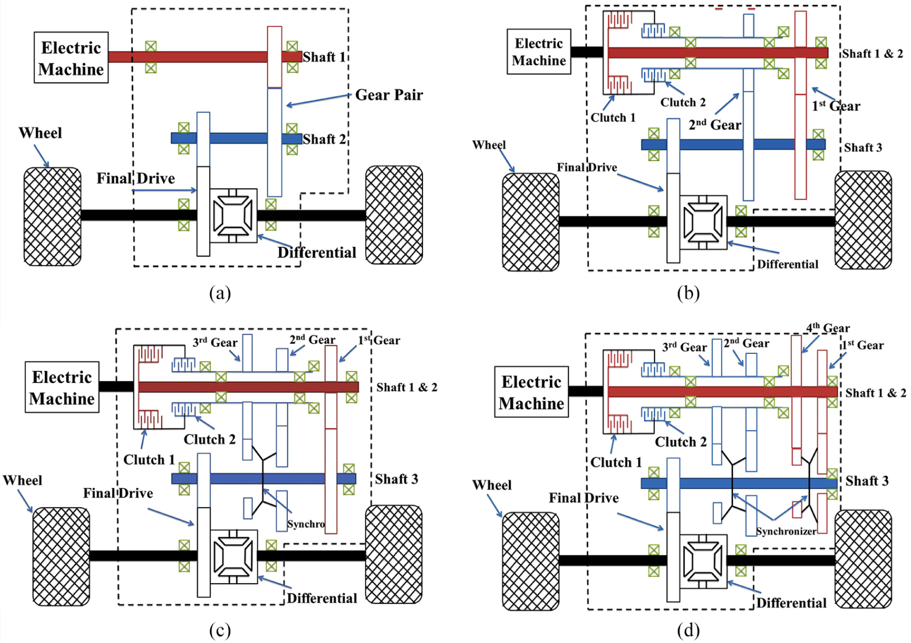
Powertrain structure: (a) single-speed, (b) two-speed, (c) three-speed, and (d) four-speed.
Simplified multi-speed stepped transmission
Multi-speed transmissions have the ability to decouple the launch, top speed, and economic driving requirements for the vehicle from the motor speed and torque range through the application of multiple available gear ratios, which is likely to improve the overall operating performance and motor efficiency of the vehicle. However, it inevitability increases the gross weight from extra components, lowers the transmission efficiency, and raises the manufacturing costs. In general, the more speeds transmission has, the better driving experience and motor efficiency can be achieved. In the meantime, more efficiency losses presented in complicated mechanisms via clutches, synchronizers, gear mesh, and so on. Differential ∼5%:
Single gear ratio friction loss 1% (only the gear pair under load);
Single gear ratio viscous loss 1% (each gear pair spinning in lubricant);
Wet clutch losses 2% ∼ 3%;
Synchronizer mechanism 1% ∼ 2%.
To retain the characteristics of smooth driving in single-speed fixed-ratio PEV, which is a significant advantage to its ICE-counterparts; DCT is selected and implemented in PEV powertrain in this study as a representative of multi-speed stepped transmission. The DCT includes two sets of parallel shafts coupled with a common clutch to the EM. Each of the parallel shafts is connected to odd or even gears. The continuous two gears should be assigned to two different shafts. Consequently, the “next” engaging gear is already ready to engage when the “current” engaged gear is still connecting to the motor. The gear shifting is realized by clutch, rather than synchronizer that used in traditional automotive transmission. For example, for a three-speed DCT, the first and third gear are on one shaft, the second gear is on the other one; for a four-speed DCT, the first and third are on one shaft, when second and fourth are on the other one. The special superiority of the two-speed DCT is that there is no synchronizer used and shifting is performed between clutches with fixed ratios. For three or more speed transmissions, a synchronizer pair is necessary for gears sharing the same axle to select alternative ratios, for instance, first and third in Figure 2(d).
A 4% ∼5% efficiency loss is inevitable for any attempt that changing speed from single to two or more due to the friction, viscous, and clutch losses. However, only 2% ∼3% extra losses per gear will be applied when speeds over two. The overall mechanical efficiencies of multi-speed gearbox are shown in Table 2. According to Zhou et al., 17 the impact of efficiency can be assessed in terms of different components.
Multi-speed dual-clutch transmission efficiency summary.

CVT: continuously variable transmission.
In summary, the benefits of using two or more speeds are improvement of motor average efficiency and vehicle driving capabilities, but it also increases the weight and cost of vehicle and decreases transmission efficiency.
Simplified CVT
The feasibility and strength of adopting the simplified CVT in a conventional PEV have been verified by simulation and bench testing.6,18 The basic concept of CVT includes two variable pulleys mounted at a fixed distance apart and connected by either metal belt or chain. Generally, only one of the two sheaves on each pulley is movable, however, two moveable sheaves are designed to eliminate belt misalignment. 19 Both radial and tangential movements are possible for the belt/chain, which depends on the loaded torque and pulleys’ axial forces.6,20
Given the requirement of hydraulic system to work with engines and provide sufficient pressure to avoid belt slipping, the efficiency of CVT is generally lower than DCT and inevitability suffers a poor speed response. 21 However, the torque converter can be removed in PEV because motor can output 100% torque from standstill without torque pulses from piston firing. Improved efficiency of actuators can be attained by replacing hydraulic pump with servo-electromechanical mechanism and optimizing belt push force control strategy.6,22,23 In addition, extra efficiency benefit can be expected from the redesign of gear sets’ direction.6,23
The efficiency of CVT is mainly depends on input torque and speed ratio. The bottom four dotted curves, in Figure 3, show the detailed power loss in an electrified CVT using above-mentioned methods. The varying efficiency range of actuators (pulleys), according to speed ratio, is represented by the top red solid curve. 6 A conspicuous monotonic increase could be found in the influence of input torque to the first three components loss. Then, the torque and speed ratio–dependent system efficiency at particular speed can be expressed as equation set


Component efficiency and power loss in CVT.
Finally, a 78%–89% overall CVT efficiency was achieved 6 and shown in Figure 4, whose mechanical layout is illustrated by Figure 5 depending on speed ratio and torque load.

CVT efficiency depending on torque load and gear ratio.
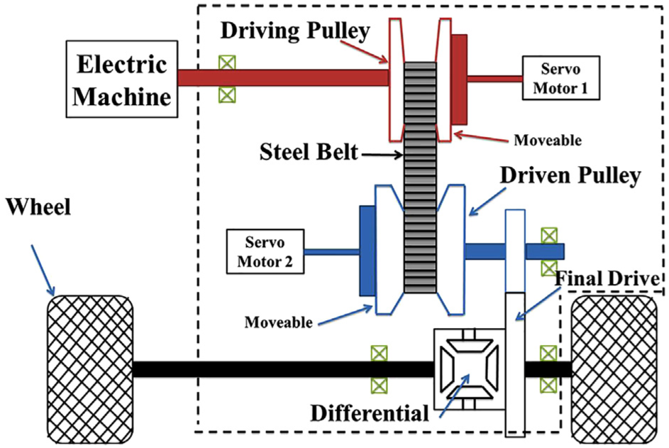
Schematic of motor-assisted CVT.
Transmission gear ratios and shifting strategy
Although the transmission design for PEV still need to follow the basic rules in mechanism, the characteristics of EM determine that the ratio range of PEV transmission is not necessary as wide as traditional vehicles.
Ratio design for stepped transmission
The largest overall gear ratio required for the powertrain is set based on greatest traction requirement, it is given in equation (3). A climbing performance of

The maximum speed is used to constraint the lowest possible ratio. A ratio lower than the value, which is defined by the maximum motor speed
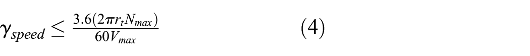
This ratio also needs to be checked against the capability of the motor to supply torque at this speed by dividing the rolling resistance and aerodynamic drag by the maximum motor torque at its maximum speed

Substitute vehicle specifications in Table 1 to equations (3)–(5), the gear ratio range of B-Class and E-Class vehicles can be determined as
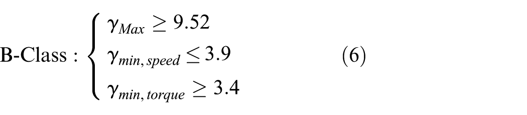
It is clear that the ratio of top speed is contradiction to the max climbing grade in single-speed ratio design, which means the single-speed transmission has to trade off the dynamic performance. There is no doubt that both of speed and grade requirements can be covered though applying a more powerful motor by extending speed and torque range. However, it will significantly increase the powertrain cost and deviate the purpose of this investigation. One of the primary goals in this study is evaluating whether the multi-speed transmission is capable to achieve a similar or better performance without upgrading motor capacity. In other words, same preconditions including motor and battery capacity should be applied to all powertrain candidates to compare the performance. In addition, dynamic performance is not the key point of this study, a reasonable gear ratio range is only the basis of the economic benefit investigation for multi-speed-transmission-based PEV. Therefore, the ratio of single-speed transmission is set as a trade-off

For a two-speed DCT, the first gear is used to acceleration and climb. The second gear is used for high-speed driving conditions, satisfying equations (4) and (5). A greater second ratio and a lower first ratio will prevent motor operating at extreme conditions, for example, maximum torque output, maximum speed output, and help motor achieve a higher average efficiency


The intermediate ratio for three and more speeds is determined by progressive methods 24
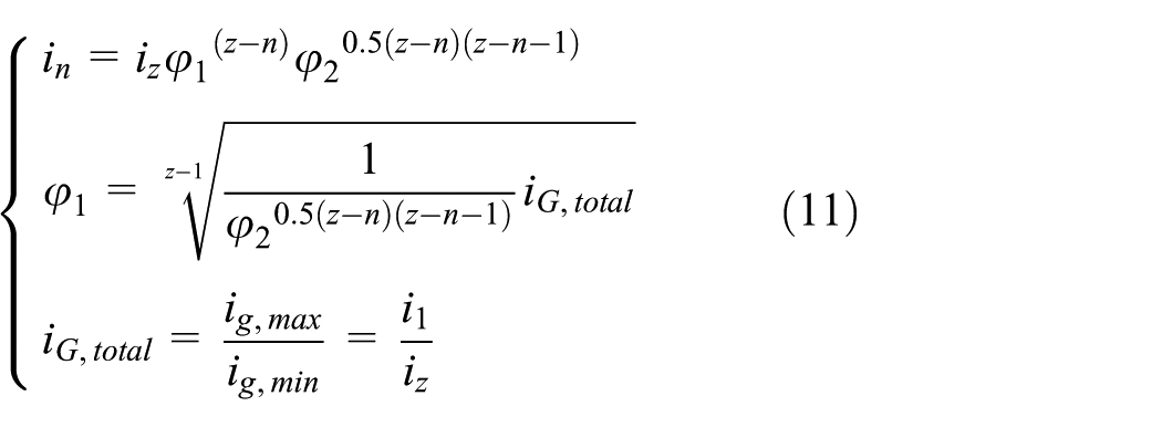

For four-speed EV

Ratio design for CVT
To evaluate the economic performance of candidate PEV transmissions based on same dynamic performance, smallest ratios are set as same in CVT to stepped transmission. Therefore, the gear range of PEV-based CVT is around three in both B- and E-class vehicles. Comparing to the current commercial CVT for traditional passenger vehicle, which easily go over seven (JATCO CVT8 25 ), the required CVT in PEV will be considerably compact and cost-effective. The speed ratios of single-speed, two- to four-speed DCTs, and simplified CVT are shown in Table 3.
Gear ratios of alternative transmissions in B-Class (E-Class).

DCT: dual-clutch transmission; CVT: continuously variable transmission.
To make this article in an appropriate length, only full simulations are presented for B-Class PEV in the following sections, and the results of all other simulations are summarized in table forms.
Application of different ratios is required to meet or improve on a number of vehicle requirements, including acceleration, top speed, and average motor efficiency. These can be viewed in terms of the vehicle traction curve. The traction load


Figure 6 shows the traction curve of all configurations that are part of this study, which is an extension of previous work. 26 The dark blue curves in all four figures are the maximum traction load at the wheel, based on motor deliverable power. The clear benefit of the PEV is that the constant power region of the motor matches well with the traction available, unlike conditions present in conventional vehicles. Thus, it becomes beneficial to use fewer gears in comparison between ICE and EVs. Considering the same ratio range of CVT and four-speed DCT in this study, they are assumed to share the same traction curve in the figure.

Traction curves of one-, two-, three-, and four-speed B-Class EV.
Shifting strategy
The gear shifting schedules of two-, three-, and four-speed DCT, shown in Figure 7(a)–(c), are based on a previous paper 6 that utilizes the mapped efficiency of the EM to maximize the driving efficiency of the powertrain depending on the selected gear ratio. The dynamic control is also considered for a power-on shift in electrified powertrain. 27 It is worth noting that the vertical part of each shifting curve is the result of speed limitation by certain gear ratio. The degree of throttle opening is defined by a value from 0 (throttle closed, no compress on accelerating pedal) to 1 (throttle fully opened, fully compressed accelerating pedal).
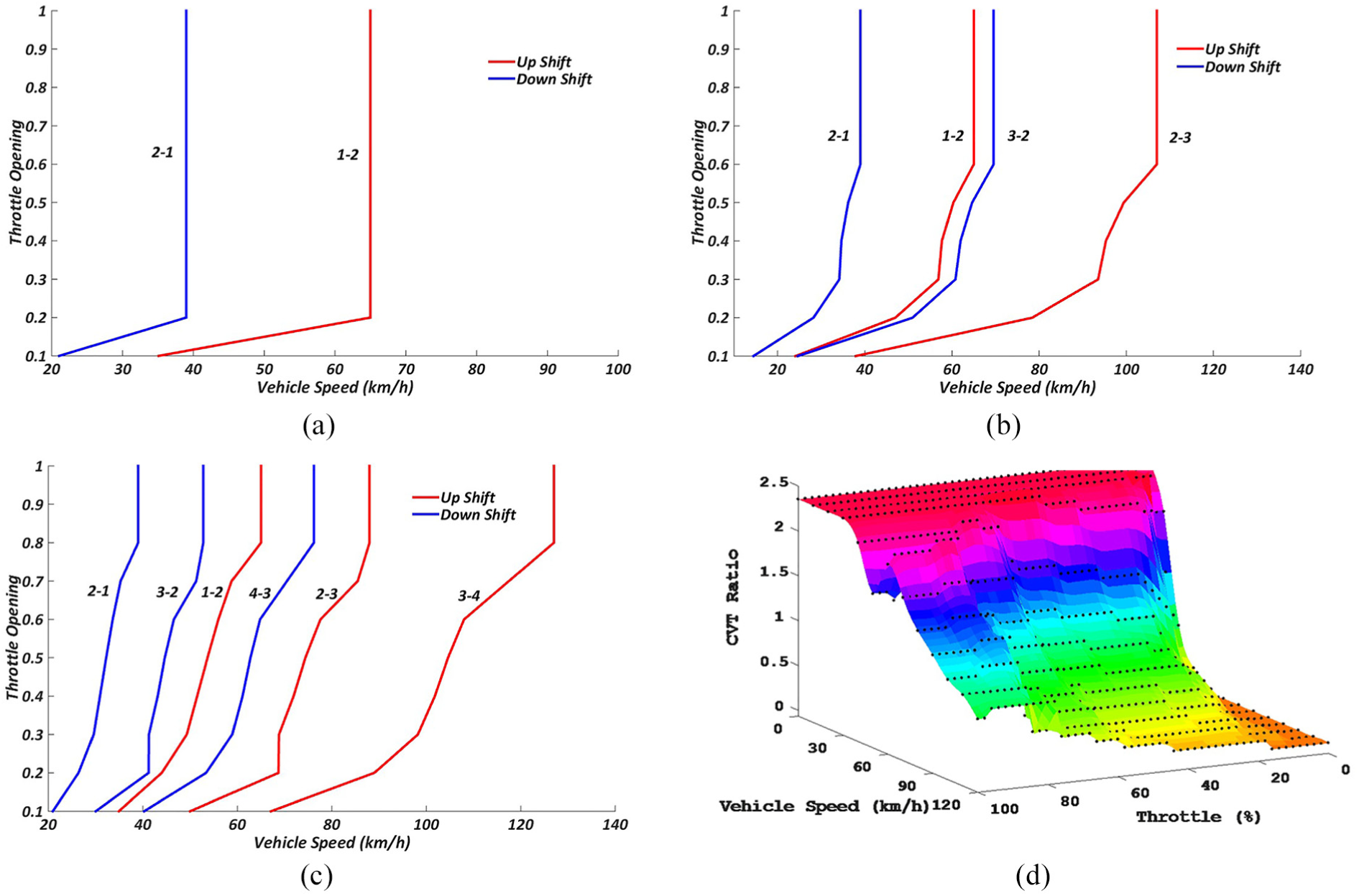
Shifting schedules of B-Class PEV: (a) two-speed shifting schedule, (b) three-speed shifting schedule, (c) four-speed shifting schedule, and (d) CVT shifting schedule.
CVT has the ability to continuously alter gear ratios to ensure the motor runs at the most efficient operating regions. The economic-oriented shifting gear ratio at particular vehicle speed and throttle position is determined via comparing motor efficiency with different gear ratios. Consequently, the economic shifting schedule of electrified CVT in PEV can be achieved, as shown in Figure 7(d). To achieve a smooth and accurate control of CVT gear ratios, advanced feedback control is applied in the Simulink® model with considering actuator faults.28,29
Simulation
Driving
Analyzing will be based on a compounded fuel economy testing cycle, which consists of city and highway (FTP-75 and HWFET) fuel economies with weightings of 43% and 57%, respectively, through equation (16). 30 An approximation of the five-cycle fuel economy values can be calculated directly from the “unadjusted” FTP-75 and HWFET fuel economy values by equations (17) and (18)31–36


KPK is the abbreviation of kWh per kilometer.
The current average driving range per driver per day is between 40 and 50 km in the United States, the United Kingdom, Australia, Singapore, and China major cities. 37 However, this range is far more away from the requirement of average daily driving mileage for home-use private vehicle. A short trip capability for EV is still an important factor for potential customers’ willingness of purchasing. According to the study, 37 the percentage of days in a whole year, when daily driving range does not exceeds 160 km, is over 95%. Considering a 32-km “range buffer” for passenger vehicle, 38 200-km one-charge range is regarded as an appropriate range for most consumers who would charge once per day only, typically at home over night.
Substitute simulation results into equations (16)–(18), the consumed electricity of PEV with various gear number in cycles are summarized in Tables 4 and 5.
Consumed electricity per 100 km of B-Class PEVs.

CVT: continuously variable transmission.
The actual operating life of the battery is affected by a lot of factors, such as charging and discharging rates, depth of discharge (DOD), and other conditions such as temperature. In addition, a normal 80% DOD is preferred in automobile application to effectively extend battery life cycle. Therefore, a 20% battery capacity design redundancy is included in this study. The required battery capacity, consequently, can be achieved.
Consumed electricity per 100 km of E-Class PEVs.

CVT: continuously variable transmission.
The actual operating life of the battery is affected by a lot of factors, such as charging and discharging rates, depth of discharge (DOD), and other conditions such as temperature. In addition, a normal 80% DOD is preferred in automobile application to effectively extend battery life cycle. Therefore, a 20% battery capacity design redundancy is included in this study. The required battery capacity, consequently, can be achieved.
As shown in above tables, comparing to fixed-ratio single-gear PEV, one additional gear significantly improves energy-utilizing efficiency by 16.4% in B-Class and 9.6% in E-Class, respectively. Specifically, regarding to B-Class, another gear (three-speed) does continuously improve the efficiency, but not as much as the first added gear due to the increased energy loss in mechanism. However, when the gear number goes to four, saved energy by increasing motor efficiency cannot cover the loss in transmission leading to a decreased energy-utilizing rate. The circumstance is different for E-Class battery electric vehicle (BEV), and the three-speed transmission does not show the benefit as it does in B-Class PEV. On the contrary, a slight energy efficiency drop is recorded comparing to two-speed powertrain. However, one more gear makes the four-speed DCT competitive to two-speed one in term of energy-utilizing rate in E-Class BEV.
Figures 8 and 9 demonstrate the motor operating tracks changing of alternative B-class PEV powertrains in city and highway driving cycles. Specific to highway driving cycle (HWFET, Figure 8), from one-speed (blue) to two-speed (red), motor operation track moved from the to a relatively high efficiency area. Three-speed (yellow) transmission moves motor operation points further to a slightly higher area. Regarding the four-speed (purple) powertrain, the motor tracks are almost same to the two-speed (red) one in most of time while the rest moves to a higher speed. Speaking to CVT (green), thanks to the continuously variable ratio and smart shifting strategy, it keeps motor working at the highest available efficiency point.
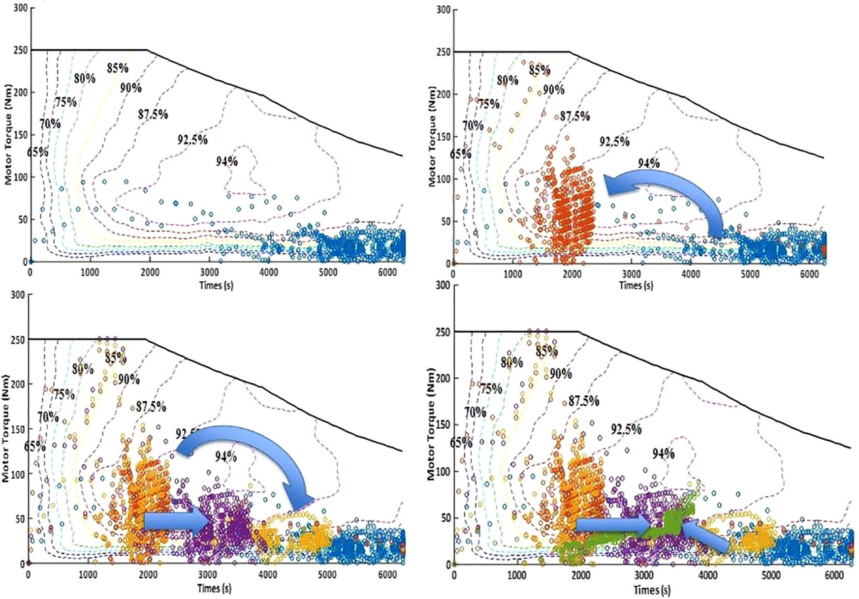
Motor operating tracks in HWFET of B-Class BEV: (top-left) single-speed; (top-right) two-speed; (bottom-left) three-speed; and (bottom-right) four-speed.
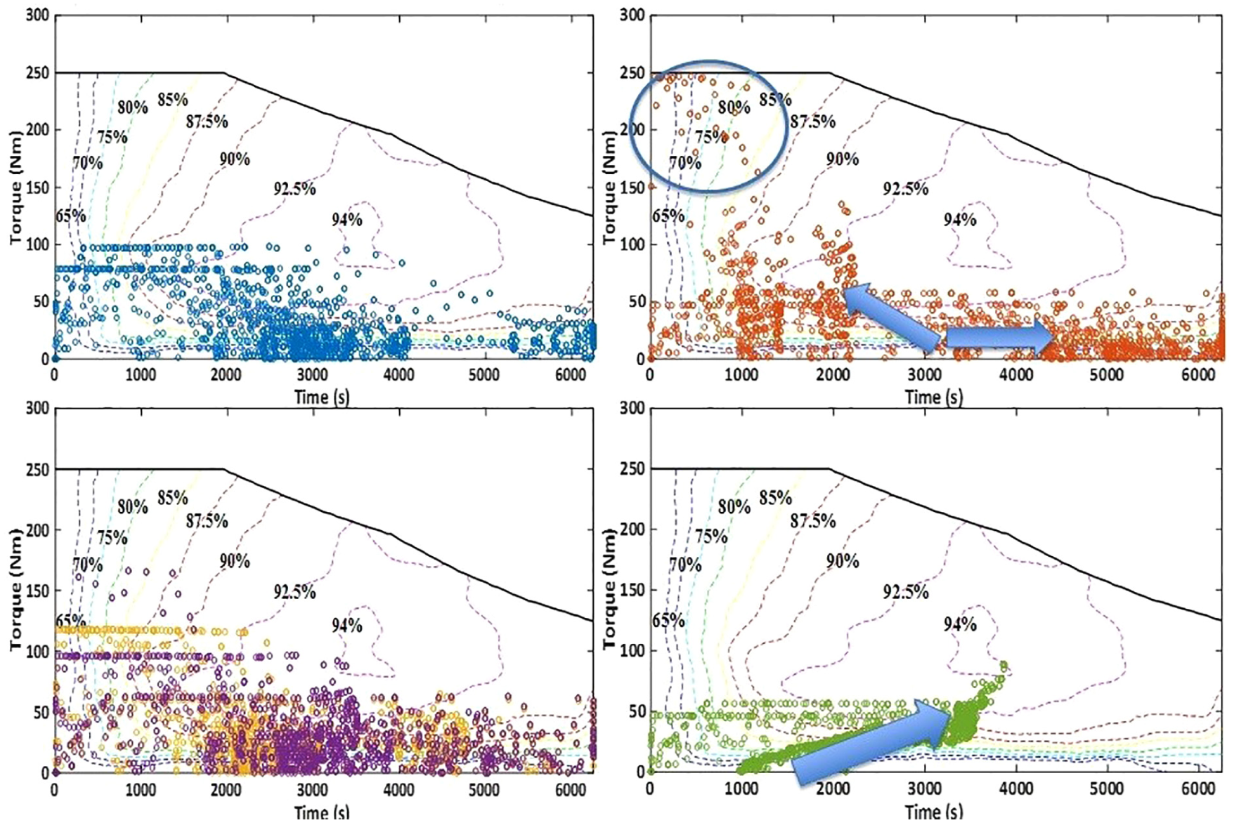
Motor operating tracks in FTP-75 of B-Class BEV: (top-left) single-speed; (top-right) two-speed; (bottom-left) three-speed; and (bottom-right) four-speed.
In terms of city driving cycle (FTP-75, Figure 9), most of the one-speed (blue)-based motor operation tracks are located in middle-speed and low-torque range, which the average efficiency is relatively low. Two-speed (red) transmission improves the average motor efficiency by increasing the motor torque through a relatively low first ratio while some motor tracks in second gear are still low-efficiency. Three- and four-speed (yellow and purple, respectively) powertrains eliminate some extreme working conditions in two-speed (red) one with a relatively high average efficiency than one-speed (blue) by increasing output torque. CVT (green)-based powertrain still outperformed other counterparts in average efficiency.
In summary, comparing to single-speed PEV powertrain, with the help of wider gear ranges and intermedia gear, multi-speed transmission-based motor operating tracks move to more efficient regions. However, there is no significant difference can be found between two-, three-, and four-speed DCT architectures. Thanks to the infinite and continuously varying ratios, CVT help motor to gain the highest average efficiency in both cycles. The comparison of ratios varying in alternative powertrains are summarized in Figure 10.
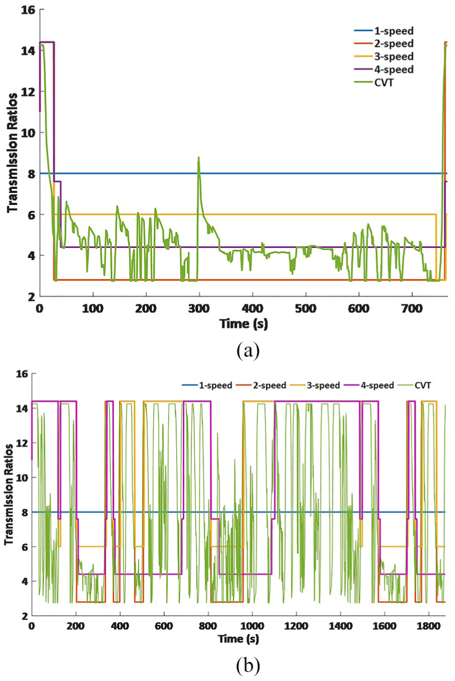
Gear ratios variation in (a) HWFET and (b) FTP-75.
Regenerative braking
Regenerative braking plays an important role in saving energy in EV. 39 The motor works as a generator and applies negative torque on axle to decelerate vehicle. In general, the conventional hydraulic brake is still necessary for PEV due to three reasons: first, the hydraulic brake is generally considered more reliable than wire brake especially when emergency brake applies; second, the regenerative brake is only available on the axle that connected to motor; third, the maximum motor brake torque is subject to its corresponding speed and not sufficient under certain circumstance. Furthermore, besides above-mentioned reasons, new issues need to be considered when a multi-speed transmission is involved in regenerative braking. As we know, the higher vehicle speed is, the larger braking force it requires to stop. To recover more kinetic energy, motor should provide braking torque as much as possible. Unfortunately, the gear ratio is usually small when significant motor brake torque is required at high speed. Consequently, the available motor brake is limited by the relative small gear ratio. Take the four-speed PEV powertrain as an example, as shown in Figure 11(a), if the vehicle speed is 135 km/h, the gear number is possibility 3 or 4, higher chance in 4. Therefore, the available motor torque through transmission is only around one-fourth of that in first gear.

(a) Available motor braking torque in each gear and (b) torque interruption in two-speed DCT bench testing.
Shifting to a lower gear is capable to increase the available motor brake, however, it will introduce torque interruption which makes the vehicle loss part of brake torque and make the driver panic though it is generally less than 1 s, it. An experimental result of torque interruption from two-speed DCT testing bench is demonstrated in Figure 11(b). Consequently, the gear should be kept unchanged in a stepped transmission. This limitation does not apply to CVT leading it to a significant advantage in braking energy recovery by varying gear ratio to provide more motor torque.
Economic benefit of multi-speed transmission to PEV
Based on the equation in “design using characteristic value,”
6
the transmission relative selling price (RSP) can be estimated by input torque

Based on the data in Tables 1 and 3, the relative gearbox selling prices are presented in Table 6. However, one-speed transmission is more like a main reducer, rather than an integrated transmission. The estimated single-speed transmission price is not appropriate. Alternatively, its price is deliberately reduced to zero in this study by assuming that the final drive gear is common to all configurations. It allows the evaluation of the multi-speed transmissions capacity to compensate for the cost of the transmission through savings realized in battery energy storage and component manufacturing costs. Comparing Table 6 to Tables 4 and 5, additional 7%–11% manufacturing costs are added to three- and four-speed transmission while only 3% and 6% energy consumption reduction received in three-speed B-Class and four-speed E-Class, respectively.
Gearboxes relative selling price to a general six-speed automatic transmission.

RSP: relative selling price; CVT: continuously variable transmission.
Comparing to the increased energy-utilizing rates, battery down-sizing is a more attractive benefit of multi-speed transmission to PEV. One additional gear, compared to single-speed, can reduce 4–5 kWh of battery capacity requirements given a 200-km pure electric driving range target. However, increasing speeds to three and four does not save much more cost on battery. The increased cost of multi-speed transmissions is taken into consideration in the following section to investigate whether the benefits of battery reduction will be offset.
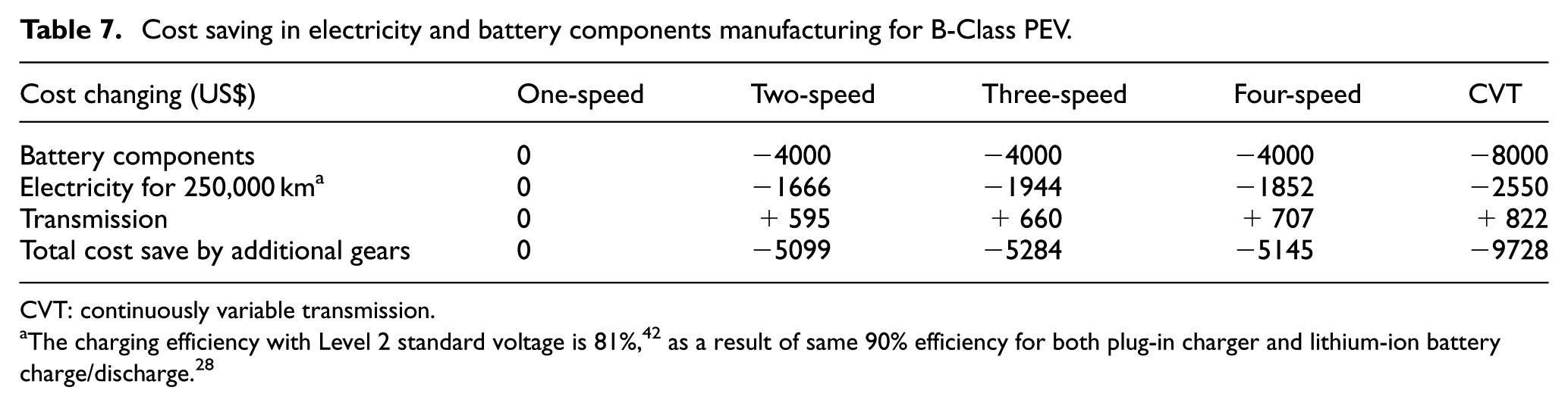
According to Ruan et al., 41 the saved cost on electricity and battery manufacturing and increased cost on transmission are shown in Tables 7 and 8, which are based on the assumption of 250,000 km vehicle lifespan, vehicle components price 43 and data in Tables 4 and 5.
Cost saving in electricity and battery components manufacturing for B-Class PEV.
CVT: continuously variable transmission.
Cost saving in electricity and battery components manufacturing for E-Class BEV.

CVT: continuously variable transmission.
From the perspective of customer, the difference between two-, three-, and four-speed are not substantial in B-Class PEV, while the achievement of CVT is outstanding as almost double as other candidates. From the perspective of Original Equipment Manufacturer (OEM), who cares more about the manufacturing cost, specifically battery and transmission in this study, CVT is also the winner, and two-speed stepped transmission is a better choice than three- and four-speeds. Regarding the E-class PEV, CVT is still the best choice for both manufacturing and customer while four-speed outperformance two-speed in this category.
Conclusion
This study reports the application of alternative multi-speed DCT and CVT to traditional single-reduction PEVs. A comparison is carried out among alternative multi-speed powertrains in a hybrid cycle, which combines city cycle, FTP-75, and highway cycle, HWFET, with weighting factors. The results demonstrate that two-speed DCT obtains the most outstanding energy-utilizing rates improvement in both B-Class and E-Class PEVs, which are 16.4% and 9.6% higher than the single-speed PEV, respectively. Unlike the three-speed DCT achieve a further efficiency improvement in B-Class PEV, it unexpectedly reduce the overall powertrain efficiency in E-Class BEV. Four-speed transmission helps E-Class PEV perform better, but it is not competitive to two-speed one in term of energy-utilizing rate in B-Class PEV. According to the simulation results, CVT is the best choice for both OEM and customer regardless the vehicle class.
In summary, it is clear that the most promising alternative transmission for PEV is CVT. It shows the greatest potential and ability to reduce the emission, fuel consumption, and manufacturing cost.
Footnotes
Handling Editor: Hamid Reza Karimi
Declaration of conflicting interests
The author(s) declared no potential conflicts of interest with respect to the research, authorship, and/or publication of this article.
Funding
The author(s) disclosed receipt of the following financial support for the research, authorship, and/or publication of this article: The authors thank the Excellerate Australia Ltd, Changsha Xiangni Auto Technology Ltd, and University of Technology Sydney for the financial support under project grant “Supercapacitor-battery based hybrid energy storage system (HESS) for light Passenger Electric Vehicle (EV) applications.” The authors also acknowledge the funding provided by the Australian Research Council through DE170100134.