
Abstract
In wave energy converters, it is hard to achieve efficient and stable energy generation because of wave instability. Based on a hydraulic transmission system of single float wave power generation equipment, this article studies the effect of throttle valve opening on power generation quality by AMESim simulation and semi-physical experiment. Results show that it is feasible to adjust throttle valve opening to improve the conversion efficiency. Besides, a hydraulic variable damping control technology is proposed to control the opening of throttle valve by monitoring wave amplitude and wave period, so as to increase the output power stability and energy conversion efficiency.
Introduction
Due to the climate change caused by greenhouse emissions and gradual depletion of oil and other fossil fuels, utilization of low-carbon renewable energy is becoming the theme of world energy development. 1 Ocean energy storage is so tremendous that it can replace fossil energy which causes plenty of environmental pollution. Utilization of ocean energy has huge economic and social significance. 2 Among all kinds of ocean energy, wave energy is the most promising one, which can be absorbed and converted into electrical energy. 3
The difficulty of wave energy development is to achieve efficient and stable conversion, because the instability of wave causes fluctuations in energy transfer process. Using hydraulic drive system to replace traditional mechanical transmission can improve the stability of the output power of the electric system. 4
The performance of wave energy conversion equipment using hydraulic as power take-off was studied by Falcão. 5 Yang et al. 6 studied a heaving-buoy wave energy converter equipped with high-pressure hydraulic power take-off mechanism. Some other studies of hydraulic Power-Take-Off (PTO) in different wave energy converter models were conducted by Eidsmoen, 7 Bjarte-Larsson and Falnes, 8 Hals et al., 9 Ding et al., 10 and others. W Sheng and A Lewis proposed a new latching technology, which could achieve a phase optimization in regular wave. Besides, the optimized power take-off damping coefficient for a given sea state was studied carefully. 11 H Shi et al. 12 studied the effects of the hydraulic damping on the motion of buoy and developed a theoretical analysis method, which was more applicable to the buoy considering hydraulic system. JF Gaspar et al. 13 adopted simulation method to better understand using a hydraulic transformer in the power take-off system. CJ Cargo et al. 14 studied the methodology for obtaining the optimum PTO damping coefficient with a given sea state, and an open-loop active tuning method was used to adjust the PTO parameters to achieve this optimum damping in service. Their investigation shows that tuning a hydraulic PTO to an estimated wave frequency is difficult due to sea-state estimation errors and complex dynamics of a real PTO.
However, the influence of throttle valve opening on output power is rarely studied. There are not sufficient physical experiments about it either. This article focuses on the hydraulic transmission system of single float wave power generation equipment and studies the effect of throttle valve opening on power generation. The first part introduces the working principle of hydraulic transmission system; the second part builds simulation model to analyze the pressure, flow rate, and power affected by the throttle valve opening; the third part builds a land experiment bench to verify the simulation results; the fourth part optimizes the system according to the findings and proposes hydraulic variable damping control technology to further enhance the output power stability; finally, the conclusions are mentioned in the fifth part.
Principle of wave energy device
Generation principle
Figure 1 shows a kind of point absorption wave power generation device which is designed according to characteristics of China’s ocean waves. It includes wave energy conversion system, hydraulic transfer system, electrical power consumption system, control and measure system.

Wave energy power generation device.
Hydraulic transmission principle
In the path to make wave energy production comparative to other conventional or renewable energy resources, researchers and developers have made their efforts to improve the wave energy conversion efficiencies by designing either efficient wave energy converters such as hydraulic power take-off, or advanced control technologies to improve wave energy capture capacity. The effects of throttle valve opening on electronic energy output can provide some references for the control mode. 15
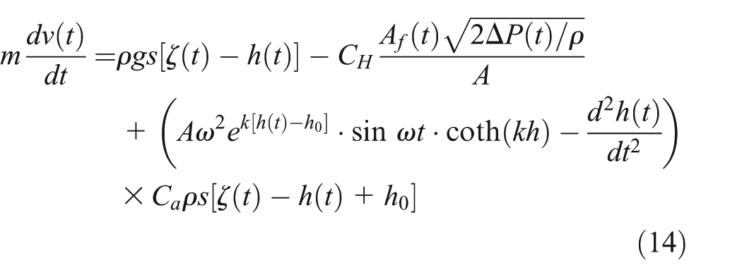
Hydraulic drive system is an effective way to ensure the stability of output power by buffering the shock caused by irregular wave energy. First, wave energy collection system converts wave energy into mechanical energy of the float. The movement of the float then converts mechanical energy into hydraulic energy. In the end, the hydraulic motor actuates the power generator to output stable electric power. Figure 2 shows a schematic diagram of the traditional hydraulic drive system. Double rod hydraulic cylinder increases the output power efficiency by discharging hydraulic oil when the float moves both up and down. Four check valves are used to constitute a hydraulic rectifier module, which ensures that the hydraulic motor remains rotating in the same direction. The accumulator serves to accumulate the surplus wave energy and produce high pressure oil. The pressurized oil is then quickly released in case of small wave fluctuation, which assures that the generator rotates at a high speed and there is little oscillation of power output. 16 The relief valve is designed or set to open at a predetermined pressure to protect pressure vessels and other equipment from being damaged. Also, the output power is regulated more stable by a reasonable match of various parts of the hydraulic drive system. 17
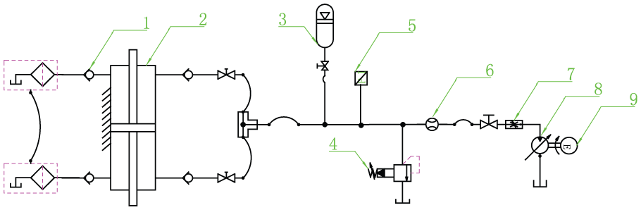
Working principle of the hydraulic transmission system.
When the buoy is pushed by wave to move upward along the guide column, it drives the piston rod of hydraulic cylinder to rise and pushes the oil of cylinder upper chamber to go into accumulator “3”. The throttle valve “7” regulates flow rate going into the hydraulic motor “8”. The motor rotates and drives the generator “9” to output continuous electric power. When the float is on the crest of the wave, it droops along the guide column under gravity and wave force. Then the oil of cylinder lower chamber flows into the accumulator. In the same way, the generator can finally outputs stable power.
AMESim simulations
Model foundation
Forces acting on the buoy include buoyancy
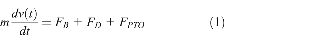

where m is the weight of buoy, v(t) is the velocity,

where

Then it can be calculated that

In deep water, the dispersion relation can be expressed as

where
It can be calculated that

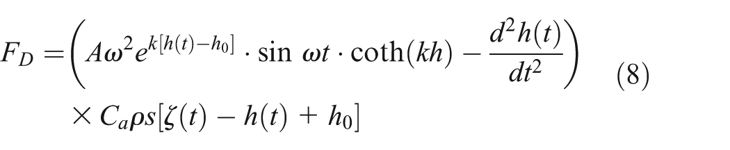
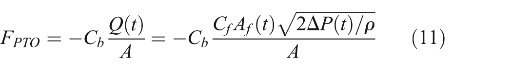
The hydraulic resistance is expressed as
where

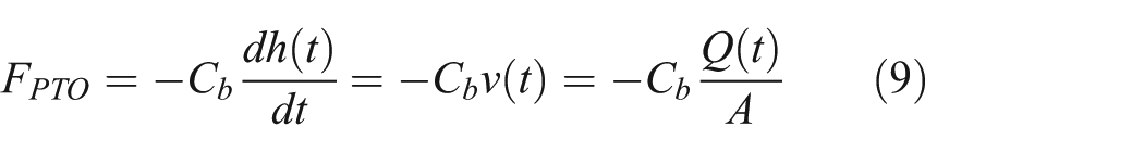
where
The change of the throttle valve opening will cause a change in flow area. From Equation (10), 18 the change of flow area will cause a change in pressure and flow rate through the throttle valve and thus impact the stability and efficiency of the power output system.
Then, it can be calculated that
Assume that
Then Equation (10) can be simplified as

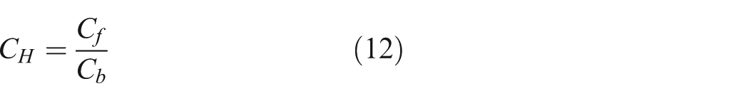
Substituting equation (1) with equations (2), (3), and (13), the governing equation becomes
The research on large electro-hydraulic system joint simulation and parameter optimization can be conveniently realized with the help of AMESim software interface. 19 According to the principle of the hydraulic transmission system, the model built by AMESim software is shown in Figure 3, which is used to simulate the effect of throttle valve opening on output power.
The simulation model.
Main parameter settings
Main parameters of the model are shown in Table 1.
Main parameters of the model.

Feasibility verification
Taking the opening of L-type throttle valve as a research object, changing its depth value is equivalent to changing the throttle opening. The Bernoulli equations on import and throttle surface of valve core are
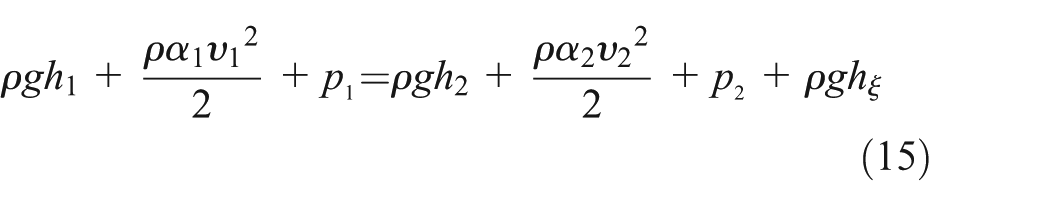

where
From equations (15) and (16), as the throttle valve opening increases, the pressure drops of the throttle valve are getting smaller. When the throttle valve opening is adjusted to the maximum, throttle’s effect is not obvious. Similar results have been obtained by simulation, as shown in Figure 4.

Throttle valve pressure drops with different opening degrees.
From Figure 4, the pressure drops of the throttle valve rise to a large value before reaching stability. When the throttle valve opening is set as 5 mm, 10 mm, and 13.5 mm, the stable pressure drops are approximately 80 bar, 20 bar, and 8 bar, respectively.
The theoretical analysis is corresponded with the simulation results, which verifies the correctness and accuracy of simulation model.
Dynamic simulation of wave energy device
Simulation of different throttle valve openings
The AMESim simulation model is used to study the influences of throttle valve opening degree on wave energy generation system. 20 The displacement of moving float is 0.5 m; the period is 5.8 s; the opening degrees of throttle valve are 5, 10, and 13.5 mm, respectively. Using batch processing to run the simulation model, the flow rate, pressure, and power of hydraulic motor are plotted in Figures 5–7:

Flow rate of hydraulic motor under different valve opening degrees by simulation.
Entrance pressure of hydraulic motor under different valve opening degrees by simulation.
Power of hydraulic motor under different valve opening degrees by simulation.
From the above curves we can see that as the opening degree of throttle valve increases from 5 mm to 13.5 mm, the flow rate, the outlet pressure of throttle valve, and the output power of hydraulic motor increased. However, the stability of the output power becomes poor, which makes the subsequent utilization of electric power difficult. Therefore, adjusting the opening degree of throttle valve is of vital importance to the stability of the output power and the efficiency of power output.
Experimental and result analysis
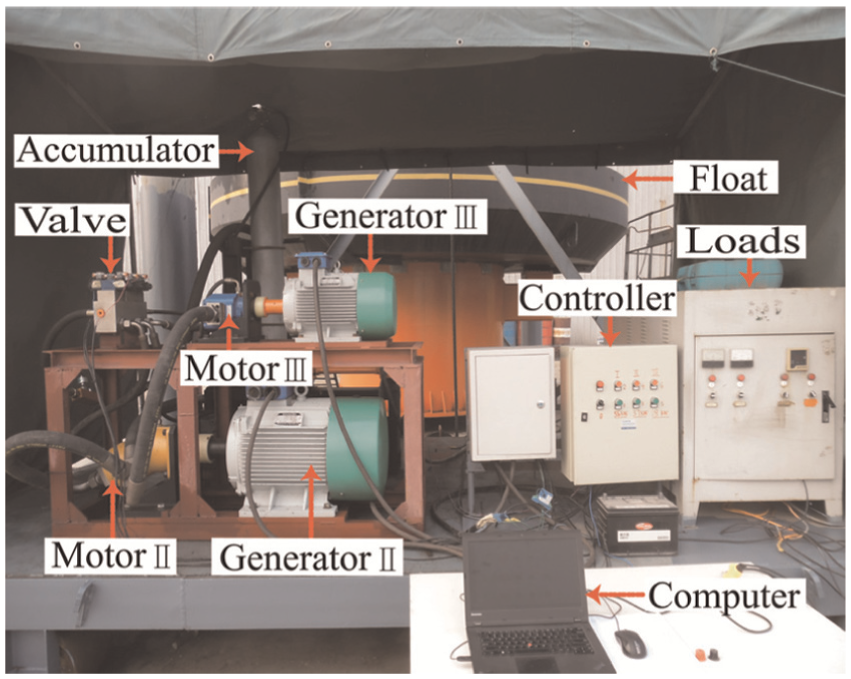
Construction of experimental apparatus
As shown in Figure 8, the land experiment bench has been built to study the influence of opening degree of throttle valve on output power and to verify the simulation results. The float is pulled up and down along the buoy by hoists, which transmits hydraulic energy into electrical energy.

Experimental apparatus.
The energy transmission system is shown in Figure 9. The displacement of the float, the output pressure and flow rate of hydraulic motor, the output voltage, and current of generator can be real-time acquired by a PC system.
Energy delivery system.
Experimental data analysis
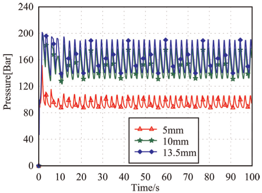
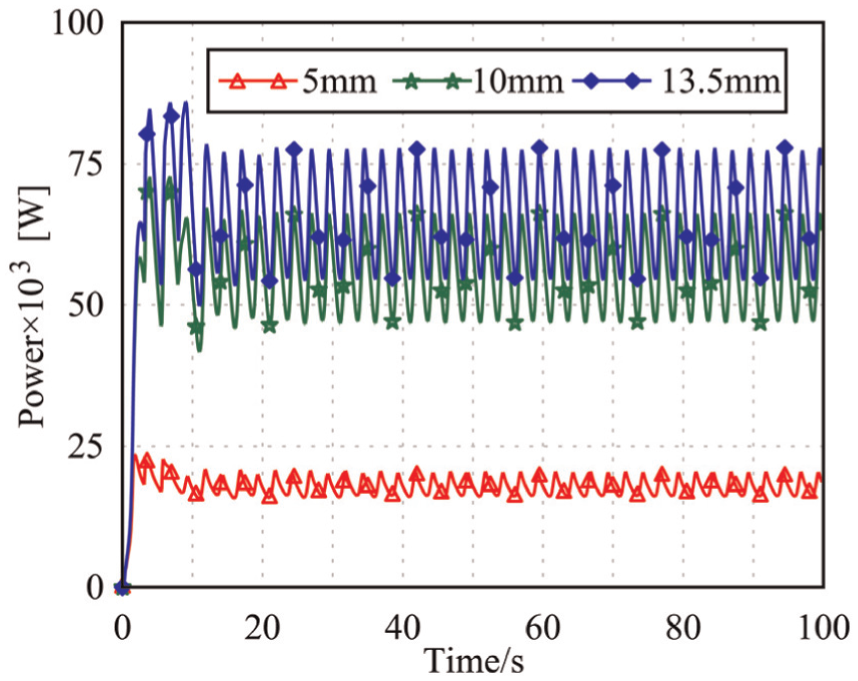
When the displacement of moving float is 0.5 m; the period is 5.8 s; the opening degrees of throttle valve are 5 mm, 10 mm, and 13.5 mm, respectively; the output flow rate, pressure, and power of hydraulic motor are plotted in Figures 10–12.

Flow rate of hydraulic motor under different valve opening degrees by experiment.

Entrance pressure of throttle valve under different valve opening degrees by experiment.
Power of hydraulic motor under different valve opening degrees by experiment.
From Figure 10, we can draw the conclusion: with the increase of throttle valve opening, the output flow of the system increased, and it achieves stable output state quickly. When the float stops moving, the greater the opening is, the faster the reducing speed is.
With the analysis of Figure 11, we can know that when the throttle valve opening is bigger, the time of the system establishing stable pressure is shorter. After the pressure being stable, the smaller throttle valve opening corresponds to the bigger entrance pressure. Figure 6 shows that when the opening degree is reducing, the pressure of valve outlet decreases. It means that the pressure drop of valve increases. This result corresponds to Equation (10) and Figure 4, which further verifies the validity of simulation model.
From Figure 12, the time used to attain power stabilization is about 40 s. There is a little difference between various opening degrees. With smaller valve opening degree, the system needs more time to stabilize. The stable output powers are approximately 8.3 kW, 7.54 kW, 7.53 kW under the opening degrees of 13.5 mm, 10 mm, 5 mm.
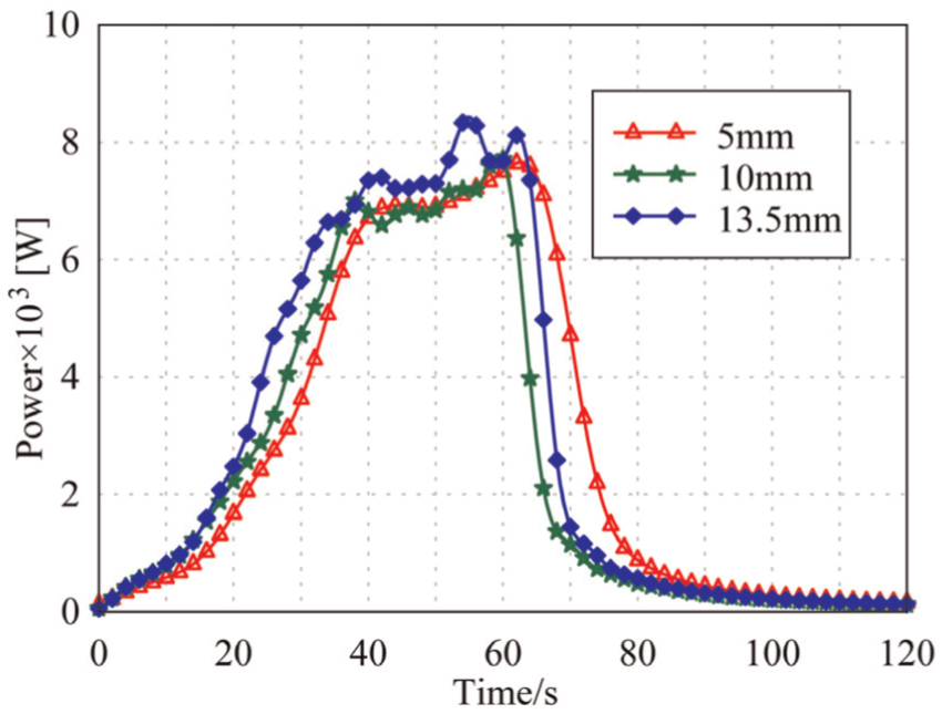
Figures 13 –15 show detection curves of the generator output voltage, current, and power. Figure 16 shows the efficiency of hydraulic energy changing into electricity at different throttle valve opening degrees.
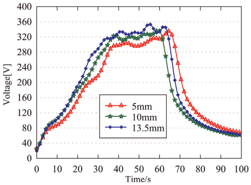
Generator output voltage curve.
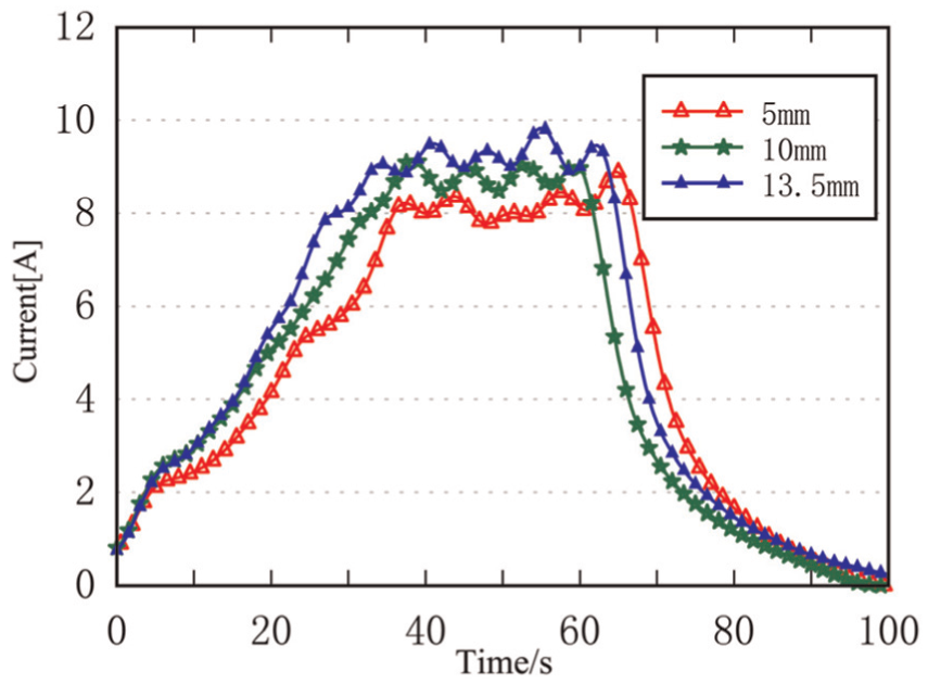
Generator output electric current curve.

Power contrast curves with different openings.

Efficiency of energy conversion.
From the above curve, along with the establishment of hydraulic motor pressure and flow rate, generator output parameters are gradually stabilized and changing regularly; when the opening increases from 5 to 13.5 mm, the generator output voltage, current and power increase, and output parameters swing more and more obviously. Besides, the generator can continuously output power for a relatively long time after the float stop moving. When the opening is larger, the system responses are faster. When the float stops moving, the output parameters of system decrease rapidly. The parameters reduce quicker when the throttle valve opens bigger. The generation efficiency reaches the top, which is 85%, when the opening degree is 13.5 mm. It indicates that the integral design of the hydraulic system is reasonable and its parameters are matched rationally.
By adjusting the opening degree of throttle valve, the continuous power output can be obtained at the time when the entrance pressure of hydraulic motor is stable. Meanwhile, the output power can be maximized and its stability can be guaranteed.
Optimization design of work principle
The degree of throttle valve opening has a great influence on the stability and efficiency of output power. To improve performance of the system, a hydraulic variable damping control technology is proposed.
The schematic of hydraulic variable damping control technology is illustrated in Figure 17. The system is mainly composed of five modules: wave energy collection module, hydraulic transmission module, power output module, measurement and control module, and energy storage module. The host computer software is developed by LabVIEW; it can be used to collect and monitor the data. The communication between the upper computer and Programmable Logical Controller (PLC) control module is enabled through the Modbus protocol to complete the command delivery. The appropriate generator and opening of the throttle valve are controlled according to the monitoring of wave amplitude and period. This ensures that the output power is stable within a certain range and also increases the output power stability.

Self-adaptive control schematic.
Figure 18 shows the output power of different generators under same small wave conditions. The curve indicates that the output power efficiency of the system decreases with the increase of the generator rated power and the time of achieving stable output varies a lot. Generator with rated power of 18 kW outputs highest power and the regulating time is relatively short with 40 s. But the stable output power fluctuates comparatively largely. By adjusting the electromagnetic valve (“7” in Figure 17) and selecting the appropriate generator in the light of wave conditions, the power efficiency can be maximized and the generator will work in its rated power proximity. In this way, the generator will not burn at the arrival of large waves.
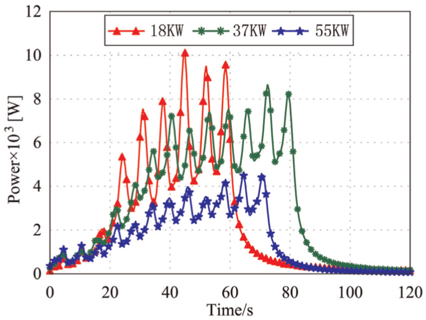
Output power curves of different generators under same condition.
According to the above study, the stability of the generator power output can be adjusted by alternating the opening degree of throttle valve (“8” in Figure 17). The question is that there is a great pressure difference between inlet and outlet of the throttle valve. Using a speed regulating valve can avoid this problem and the heat of the fluid can be reduced a lot. The specific experiment of the speed regulating valve will be carried out after the equipment is completely modified.
Efficiency estimation of power generation
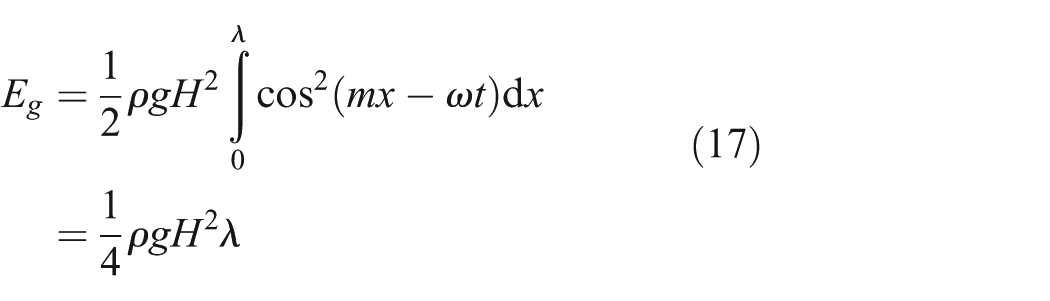
The wave potential energy per unit wavelength width is 21
The fluid kinetic energy of a given incompressible fluid in a non-swirling flow can be expressed as

The flow field volume in equation (18) is

Then the kinetic energy can be written as

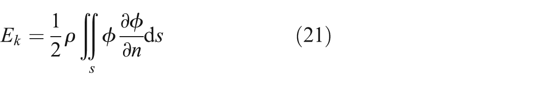
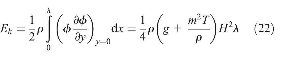
In addition, the flow field has kinetic energy due to the movement of fluid particles. The wave kinetic energy per unit width is given as
Under the precondition of linearization, the wave front integral boundary is simplified as
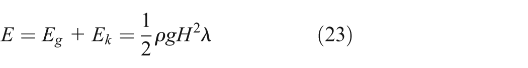
If the surface tension is not included, the total energy of the wave is the sum of the gravitational potential energy and the kinetic energy. 22 The total energy is
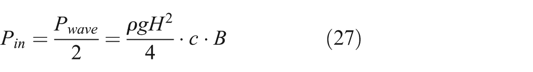
The power per unit wavelength width is

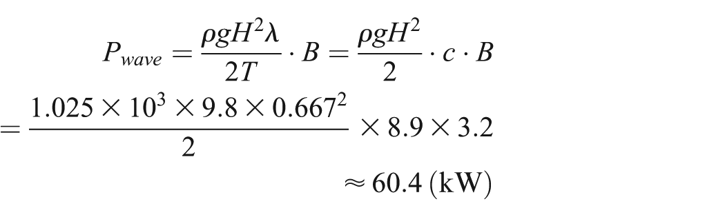
The total wave power in the float width is


where
In addition, one can solve

The energy transmission is half of the total wave energy, that is, the energy absorbed by the float in the trap width is
The displacement of the float is about three-fourths of the height of wave. 23 Assume that the motion amplitude of the float is 0.5 m, the wave height is about 0.667 m.
When the wave period is 5.8 s, and the depth of operation sea is 30 m, one can calculate the input of wave energy and the efficiency of power generation system.
The wave number is obtained from


Wave propagation speed is

The total wave power in the float width is

From Figure 18, it can be seen that when selecting different generators, the intermediate power is 7.48 kW and the maximum power is 9.95 kW, and then the generation efficiencies are


By rationally selecting the generator and adjusting the throttle valve opening degree, the efficiency of power generation can be improved and output power stability can be obtained. Further improvements such as matching the diameter of the pipeline will be done to further improve the generation efficiency.
Conclusion
In this investigation, the effect of throttle valve opening on the output power of wave energy generation system has been discussed. The conclusions are as follows:
Through the comparative analysis of theoretical method, AMESim simulation, and physical experiments, it has been verified that the simulation model is correct and research results are reliable.
The degree of throttle valve opening has a significant influence on power output apparatus. When the valve opening becomes larger, the time to output stable electrical energy is shorter. Meanwhile, when the float stops moving at the end of several periods, the energy output decreases rapidly. Adjusting the opening degree of throttle valve in real-time according to various wave conditions can not only guarantee the maximum power output but also ensure the continuity of power output.
The energy output states with different generators in the same wave condition have been researched. When the wave height is small, the generator with smaller rated power can output larger electrical energy due to the relatively small inertia torque. However, the output power fluctuates more, which means that the generator with lower rated power has poorer stability. On the basis of the above study, a hydraulic variable damping control technology is proposed. Its main idea is to improve the output electrical energy quality by switching the generator model and changing the throttle valve opening degree.
The technical difficulty of adaptive variable damping is to find the optimal opening degree of throttle valve in a certain wave amplitude and period condition. By analyzing an adequate amount of experiment data, the optimal matches can be found.
4. The average efficiency of hydraulic energy converting into electric energy can reach 85%, which proves that the design of the hydraulic system is very reasonable. The maximum efficiency of electricity generation can reach 32.9%.
Footnotes
Academic Editor: Yucheng Liu
Author Note
Affiliation for authors Wei Zhang, Yanjun Liu Shizhen Li, Tongtong He and Jingwen Liu has been updated from School of Mechanical Engineering, Shandong University, Jinan, China to Mechanical Engineering Institute, Shandong University, Key Laboratory of High Efficiency and Clean Mechanical Manufacture, Ministry of Education, Jinan, China
Declaration of conflicting interests
The author(s) declared no potential conflicts of interest with respect to the research, authorship, and/or publication of this article.
Funding
The author(s) disclosed receipt of the following financial support for the research, authorship, and/or publication of this article: The research was supported by the Fundamental Research Funds of Shandong University (Project No. 2016JC035) and the Natural Science Foundation of Shandong Province (Project No. ZR2016WH02), which are gratefully acknowledged.