
Abstract
Air-temperature vaporizer is the main equipment of LNG satellite station vaporization process, and the core equipment of the whole supply system, whose vaporization capacity decides the gas supply scale of LNG satellite station. The heat transfer effect of finned tube mostly affects the vaporization capacity of air-temperature vaporizer and also affected by many factors such as ambient temperature. Therefore, this research aims to study the heat transfer of finned tube in air-temperature vaporizer. With the actual case calculated and analyzed, the research has established the mathematical model of heat and mass transfer based on MATLAB program, with which the required length of finned tube is calculated. On comparing the results of simulation with actual ones, the reliability of the model is verified. According to the studies of the effects of air temperature, fin height, number of fins, and vaporization of LNG on the heat transfer process, the search sums up that the heat transfer performance of finned tube increases with the increase in air temperature, fin height, and vaporization of LNG although the effects are not obvious. The research has also calculated the length of finned tubes under different operating conditions. By comparing the outlet temperatures, the research summarizes that the most appropriate number of fins is 8.
Introduction
Air-temperature vaporizer is the main equipment of LNG satellite station vaporization process, in which LNG goes through the gas–liquid two-phase area, namely, boiling heat transfer two-phase flow area. With the finned tube being one of the most important parts of air-temperature vaporizer, boiling heat transfer two-phase flow and vaporization capacity are critical factors that affect the heat transfer effect.
There are several studies on air-temperature vaporizer in LNG satellite stations while most of which mainly research the heat transfer area. Therefore, this research aims at studying the effects of boiling heat transfer two-phase flow and vaporization capacity of finned tubes.
Boiling heat transfer two-phase flow
The heat transfer process of boiling heat transfer two-phase flow is more complex, so it becomes a hot topic in the same research. At present, there are many researches on boiling heat transfer two-phase flow, and many experimental correlations are proposed. In 1966, Chen J C first studied the boiling heat transfer two-phase flow. Through experimental research and suitable calculation method, the heat transfer law of boiling heat transfer was obtained, and finally the Chen 1 relation was obtained. In 1986, KE Gungor and Winterton 2 analyzed the experimental data and summarized the characteristics and laws of the boiling heat transfer of organic medium, and got the Gungor–Winterton relation. In 2007, SL Qi et al. 3 used liquid nitrogen as the object of study, conducted an experimental study on the horizontal tube boiling heat transfer, and analyzed that liquid nitrogen flow patterns were mainly wavy and slug flow; analysis of the relationship between Klimenko and Klimenko 4 is a relatively accurate correlation, while Shah and Chen’s correlations show a low heat transfer coefficient. In 2000, L Cheng and Chen 5 used kerosene as the research object, and the heat transfer process was studied by experimental method. Six different boiling heat transfer relations were analyzed, and finally the two relations with the lowest error were obtained, which is known as Shah and Kandlikar relation. In 2008, SM Wang et al. 6 analyzed the mechanism of boiling heat transfer, modified the bubble parameter model in the supercooled boiling model, and obtained the subcooled boiling calculation model for liquid nitrogen. In 2009, M Gong et al. 7 studied the heat transfer process of pool boiling by experimental method, and analyzed the effect of ethane and propane on the heat transfer effect, and compared the experimental results with the calculation results of existing relational formulas. In 2010, XD Li 8 used liquid nitrogen as the object of study, and liquid nitrogen in the vertical tube flow boiling heat transfer established a two-fluid model, obtained by gas–liquid phase transmission law, and the numerical results coincide with Klimenko’s the experimental measurements. In 2010, the MUSIG model was used to calculate the subcooled boiling process of the cryogenic fluid. The subcooled boiling process of the liquid nitrogen in the vertical tube was simulated. The relationship between the size of the tube and the ratio of the void ratio and the instability of liquid nitrogen was studied. 9 In 2011, Chen Shuping applied the multiphase mixture model to the simulation of the liquid nitrogen transformation process, and analyzed the heat transfer, pressure drop, and gas flow rate of the air-temperature carburetor with the inlet flow rate. 10 In 2011, CC Yang 11 simulated the heat and mass transfer process of the LNG air-temperature carburetor, and calculated the heat transfer of the boiling heat transfer process with Klimenko’s heat transfer equation, and analyzed the effects of LNG and air temperature. Heat transfer process, the increase in methane content is conducive to air-temperature vaporizer heat transfer of the conclusion.
Finned tube heat transfer study
In 2007, with the longitudinal finned tube as the research object, the heat transfer process of natural convection was studied by numerical simulation and experiment. The structural parameters of finned tube and fin spacing were analyzed, which provides a theoretical basis for the design and construction of finned tube heat exchangers. 12 In 2009, M Wang et al. 13 used the experimental method to study the heat transfer process of the circular finned tube heat exchanger installed in the wind tunnel, and the experimental results were fitted to obtain the heat transfer in a certain flow rate range. Coefficient and the resistance coefficient of the tube bundle provide the theoretical basis for the optimization design and selection of the finned tubes of the same type. In 2011, Li Dashu studied the heat transfer of longitudinal finned tubes, analyzed the calculation method of heat transfer coefficient under different heat transfer conditions, and put forward the design process of longitudinal finned tube heat exchanger. The case for the longitudinal finned tube heat exchanger design theory is to be verified. 14
Through detailed study on heat and mass transfer process of air-temperature vaporizer, this research has acquired valuable conclusions, which will provide theoretical basis for design, construction, and operation of air-temperature vaporizers.
Theory
Analysis of heat and mass transfer process of air-temperature
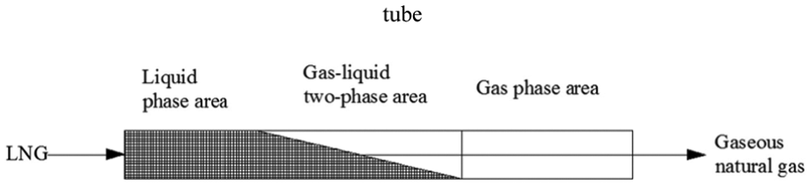
The heat and mass transfer of the air cooled vaporizer is mainly divided into three parts: the natural convection heat transfer outside the tube, the heat conduction in the tube wall, and the convective heat transfer between the LNG and the finned tube, as shown in Figure 1. The heat and mass transfer in tube LNG and fin tube is a forced convection boiling heat transfer in the heat transfer process of the Zhang, 15 and can be described as follows: LNG mixture enters at the bottom of the vaporizer, by constantly absorbing heat, the temperature gradually increases, when the temperature reaches the boiling point, liquid vaporization, the first is the low methane bubble group the air bubbles, then ethane and propane were vaporized, makes the liquid composition change; as the temperature continues to rise, when the mixture reaches the dew point, all liquid gasification gas after gasification, outflow from the upper part of the carburetor, the carburetor gas export and import of liquid components of the same. As can be seen in Figure 1, LNG in the finned tube gasification process consists of three parts, namely, liquid phase, gas–liquid two-phase region, and gas phase area.
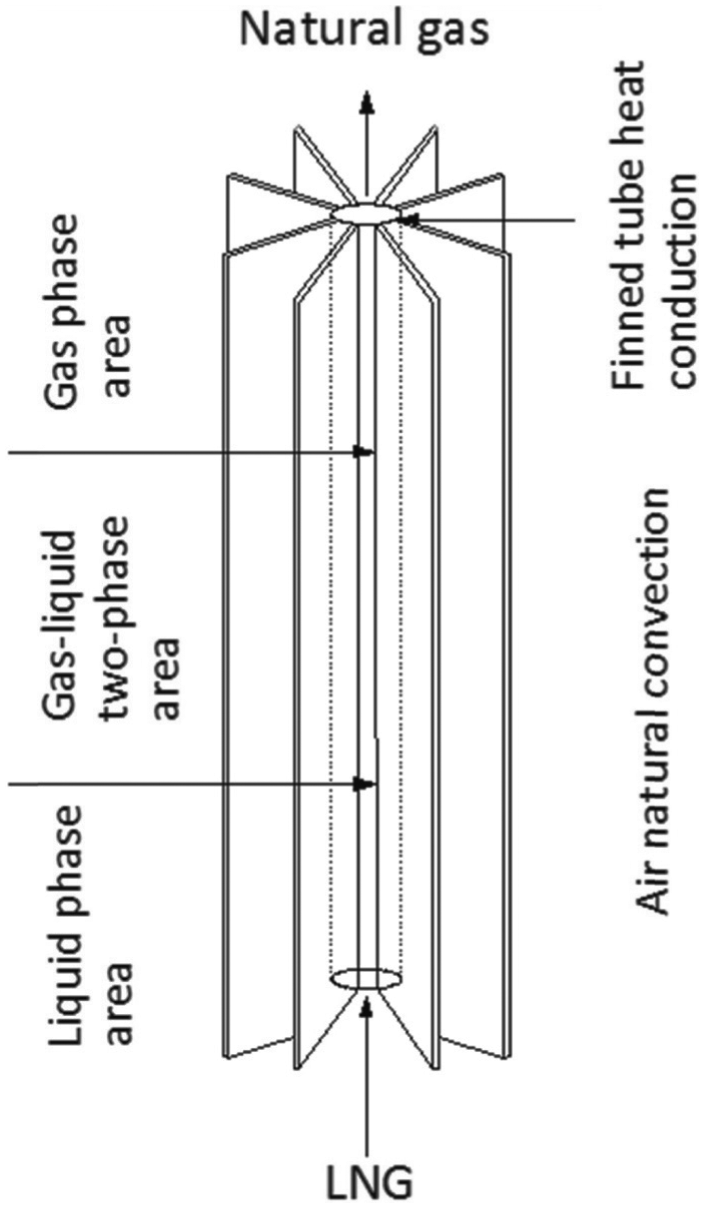
Schematic diagram of heat and mass transfer in finned tube.
Analysis of heat and mass transfer in gas/liquid phase
The single-phase gas/liquid region of LNG in finned tube can be considered as forced convection heat transfer without phase change.
Analysis of heat and mass transfer in gas–liquid two-phase region (boiling)
The gas–liquid two-phase flow in the finned tube of an air cooled vaporizer is a two-phase flow of boiling heat transfer. The heat transfer process of LNG is related to the flow pattern of fluid flow.16–19 LNG from the bottom into the finned tube, along the length of the part to absorb external heat, continuous vaporization of bubbles, with the endothermic process continued, bubble formation and growth, gradually rising, jumping off, change the heat transfer process and the flow chart is shown in Figure 2.

Heat transfer and flow pattern of forced convection boiling of cryogenic liquid in a vertical tube.
Figure 2 shows that when the fluid is in the A part, the temperature is lower than the bubble point temperature and the wall temperature is lower than the bubble point temperature; thus, no vaporization occurs, the fluid flow and single-phase liquid flow pattern for the same, forced convection heat transfer of the single-phase fluid, the heat transfer coefficient is relatively low; when the fluid is in the B part, the tube wall temperature is higher than the liquid bubble point temperature, on the wall of bubbles and gradually enter the mainstream region, this time in the subcooled boiling, the fluid flow pattern is a fine bubble, the heat transfer coefficient increases; when the fluid is in the C part, the temperature of the liquid reaches the saturation temperature, liquid vaporization bubble, the bubble is saturated boiling, fluid flow is still a fine bubble, the sudden increase in heat transfer coefficient; when the fluid is in the D part, the temperature of the liquid and the wall temperature are almost the same, the heat absorbed to the vaporization of liquid, so the percentage of bubbles increases, the flow pattern is slug flow, the main heat transfer for saturated bubble boiling heat transfer, heat transfer coefficient is relatively stable, but larger; when the fluid is in the E part, the temperature is the same as D part, the difference is that the fluid flow pattern for annular flow, heat transfer in forced convection heat transfer of liquid film; when the fluid is in the F part, temperature is the same as the D part, the difference is that the fluid flow pattern for entrainment-shaped annular flow, heat transfer in forced convection heat transfer of liquid film; when the fluid is in the G part, the liquid in the tube is almost completely evaporated, and the steam tube wall contact heat transfer, the tube wall temperature increases, air liquid by heating and evaporating, flow pattern as the mist, the heat transfer coefficient increases sharply; when the fluid is in the H area, all the droplet in the air evaporated, so the heat transfer in this area is a single-phase gas convection heat transfer, and the heat transfer coefficient is small.
Through the above analysis, the boundaries of the gas–liquid flow pattern and heat transfer mechanism are not completely consistent, the mechanism of heat tube popular transition region is the same, there is a close relationship between the changes of flow patterns and heat transfer coefficient of the fluid, the heat transfer coefficient of single-phase liquid zone is low, the heat transfer coefficient and large stable two-phase region, single-phase gas the minimum heat transfer coefficient.
Mathematical model of heat and mass transfer of air-temperature vaporizer
Before building the model, make assumptions about the model:
The composition and temperature of the natural gas in the carburetor are uniform everywhere;
It is considered that the heat transfer is fully developed;
The pressure is constant during the operation of the gasifier;
The fluid flow in a tube is approximated by a one-dimensional (1D) steady state;
The air outside the tube in the humid air, without considering the influence of frost.
The outside of the tube for the natural convection heat transfer of air, without considering the effect of the wind. Under the above assumptions, the overall model of heat and mass transfer of the air-temperature vaporizer is shown in Figure 3. The micro-model is shown in Figure 4.
Heat transfer model of air-temperature vaporizer.

The element model of air-temperature vaporizer.
Single-phase region
Convective heat transfer in tube
Energy conservation equation as shown in equation (1)
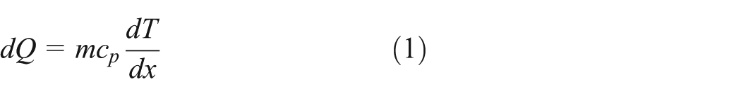
where dQ is the heat absorbed by micro-unit in unit time, W; m is the mass flow per unit time infinitesimal segment, kg/s; cp is the specific heat capacity at constant pressure of fluid in tube, J/kg K; dT is the fluid temperature inside the tube, K; and dx is the length of the micro-element, m.
For forced convection heat transfer process, heat transfer equation for the Newton cooling formula, as shown in equation (2)

where α is the forced convection heat transfer coefficient, W/(m2 K); D1 is the diameter, m; Tw is the tube wall temperature, K; Tf is the fluid temperature, K.
Finned tube wall thermal conductivity
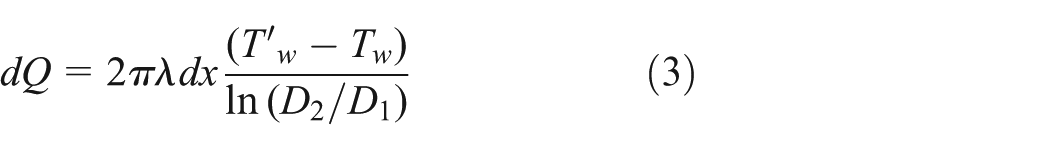
The heat conduction of the fin tube wall using Fourier’s law, where λ is the thermal conductivity of wall material, W/(m·K);
Air side convection heat transfer
For air side convection heat transfer, Newton cooling formula, as shown in equation (4)

where α0 is air side natural convection heat transfer coefficient, W/(m2 K); l is the fin height, m; δ1 is the fin thickness, m; n is the number of single fin of finned tube; w is the fin efficiency;
Two-phase region
The model of heat transfer and heat transfer in the air duct and tube wall of the two-phase region is basically the same as that of the single phase, but the heat transfer coefficient is different. For the gas–liquid two-phase convection heat transfer in the tube, it is more accurate to calculate the boiling heat transfer of Klimenko.
Boundary condition
Inlet fluid temperature

Outlet fluid temperature

Inner wall temperature

Outside wall temperature

Mathematical model of heat and mass transfer for air-temperature vaporizer
Discretization of equation
Convective heat transfer in tube


Finned tube wall heat conduction

Natural convection heat transfer

Computation method
Based on the mathematical model of heat and mass transfer process in air-temperature vaporizer, this section separates the process into three parts, namely gas phase flow, gas–liquid two-phase flow, and liquid phase flow and calculated them with block diagram (Figure 5).
Heat and mass transfer calculation of gas phase flow and liquid phase flow
Assume that the micro-segment outlet temperature is T1(i + 1);
Calculate the external convective heat transfer coefficient cx0(i) using the empirical formula of the outside air, assuming the temperature Tw0(i) of the tube outer wall of the micro-element segment;
Calculate the wall temperature Tw1(i) according to the heat transfer formula of tube wall;
Calculate the convective heat transfer coefficient cx(i) according to the convective heat transfer criterion;
Calculate the temperature Tw2(i) of the inner wall of the tube according to the heat flux and the temperature of the fluid in the tube;
Calculate the absolute value of Tw2(i) − Tw1(i), if less than 0.1, then the assumed tube wall temperature is appropriate; otherwise, repeat step (2) until the assumed temperature is appropriate;
Calculate the absolute value of T2(i) − T1(i) if the micro-segment outlet temperature T2(i + 1) is calculated from the heat transfer quantity Q(i) of the micro-segment, if <0.1, temperature, otherwise repeat step (1) until the temperature is assumed to be appropriate;
For liquid phase flow, when the fluid temperature is higher than the bubble point temperature (Ts), the program ends. While for gas phase flow, when the fluid temperature is higher than the outlet temperature (Tout), the program ends.
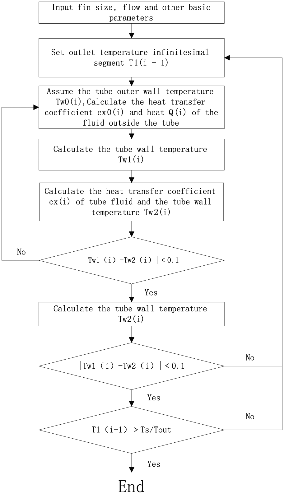
Flow diagram of gas phase flow and liquid phase flow.
Heat transfer calculation of fluid flow in gas–liquid two phase
Assuming the temperature Tw0 of the tube outer wall of the micro-element segment, the external convective heat transfer coefficient cx0 is calculated using the empirical formula of the outside air of the tube;
Calculate the micro-element heat Q, calculate the tube wall temperature Tw1 according to the heat transfer formula of the tube wall;
Calculate the convective heat transfer coefficient cx according to the convective heat transfer criterion;
Calculating the temperature Tw2 of the inner wall of the tube based on the heat flux and the temperature of the fluid in the tube;
Calculate the absolute value of Tw2 − Tw1, if less than 0.1, the assumed tube wall temperature is appropriate; otherwise, repeat step (1) until the assumed temperature is appropriate;
According to the length of heat transfer unit, calculate the length of two-phase gas–liquid phase (Figure 6).
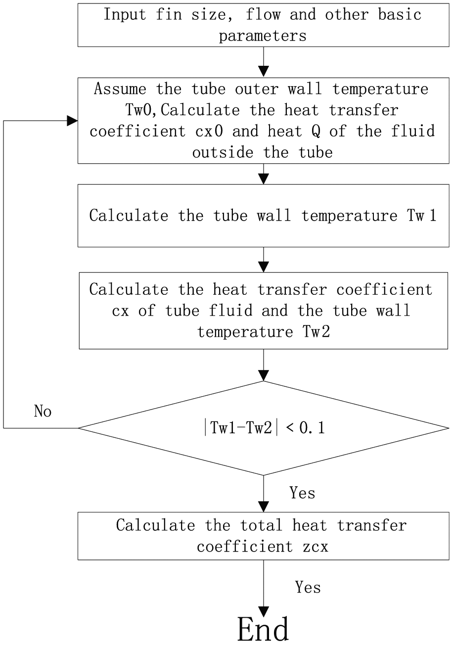
Diagram of fluid flow and heat transfer in gas–liquid two-phase flow.
Case study
Basic parameters
The parameters of the air-temperature carburetor of a LNG satellite station are shown in Table 1. The finned tube is made of aluminum alloy and the structure of the fin tube is shown in Figure 7. In actual operation, the inlet temperature of the fin tube is −162°C, and the outlet temperature is not lower than the ambient temperature of 5°C.
The parameters of the air-temperature carburetor of a LNG satellite station.


Finned tube structure parameters (unit: mm).
Calculation results and analysis
Based on the block diagram and calculation step introduced above, this section calculates the process of fluid interchange of liquid phase flow using the MATLAB program. The results are analyzed as follows:
1. The heat transfer coefficient of convection tube along the length of the change.
It can be seen from Figure 8 that the length of the fin tube is 13.8 m and the convective heat transfer coefficient is 2571.2 W/(m2 K) in the gas–liquid two-phase region, the heat transfer coefficient in the liquid region is second, the convective heat transfer coefficient in the gas phase region is the smallest.

The convective heat transfer coefficient with tube length.
2. The natural convective heat transfer coefficients along the air side of the tube vary along the tube length.
It can be seen from Figure 9 that the natural convection heat transfer coefficient of the out-of-tube air is the largest in the liquid phase and is in the range of 10–12 W/(m2 K), and the heat transfer coefficient in the gas–liquid two-phase region is 10.56 W/(m2 K), the gas phase region is the smallest, which is less than 11 W/(m2 K).

Variation of natural convection heat transfer coefficient of air outside the tube.
3. The overall heat transfer coefficient of fin tube along the tube changes.
It can be seen from Figure 10 that the total heat transfer coefficient of the finned tube is in the range of 160 W/(m2 K), the total heat transfer coefficient is 95.75 W/(m2 K). The total heat transfer coefficient in the gas phase is about 60–150 W/(m2 K).

Variation of overall heat transfer coefficient of finned tube with fin tube length.
In summary, the finned tube length of 13.8 m, and the actual length of 15 m, due to the actual process design will take into account a certain margin, so greater than the calculated length, can explain that the model has a certain reliability.
Discussion
There are many factors that affect the heat transfer of the air-temperature carburetor. The main factors are the temperature of the air outside the tube, the height, and the number of fins.
Effect of air temperature on heat transfer
The influence of different air temperature on the heat transfer is studied. The influence of different air temperature on the heat transfer coefficient is studied at different temperatures: 10°C, 0°C, 10°C, and 20°C.
Figure 11(a) shows that with the increase in the temperature of the air outside the tube, the tube heat transfer coefficient increases gradually, but increased, so the air outside the tube temperature of the fluid in the tube heat transfer coefficient is insensitive.
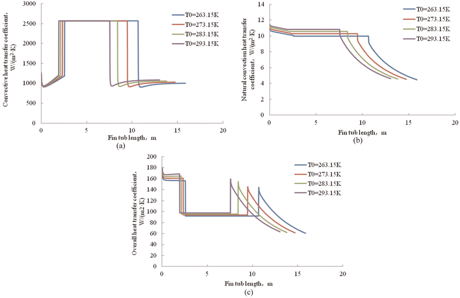
Effect of temperature on different parameters: (a) convective heat transfer coefficient, (b) natural convection heat transfer coefficient, and (c) overall heat transfer coefficient.
Figure 11(b) shows that the with the increase in the air outside the tube temperature obviously, liquid phase and two-phase tube of the air side natural convection heat transfer coefficient increases gradually, the gas phase section of the air outside the tube side of the natural convection heat transfer coefficient decreases gradually, and in fact, liquid phase and gas phase, two phases increase because of the length of the starting point of gas phase section of the location is not the same; if the starting point is set to the same location, we can observe the gas phase is increased, thus increasing the temperature of the air outside the tube so that the air outside the tube side of the natural convection heat transfer coefficient increases, thereby affecting the total change thermal coefficient.
As can be seen from Figure 11(c), with the increase in air temperature outside the tube, the total heat transfer coefficient increases gradually, and the amplitude is larger.
Figure 11 shows, when the air temperature was −10°C and 0°C, 10°C and 20°C, the fin tube lengths were 15.88, 14.74, 13.8, 13.04, the length change is not large; therefore, the heat transfer performance of finned tube increases with the increase in air temperature, but the effect is not obvious.
Effect of fin height on heat transfer
In this article, the height of finned tube is studied with 75, 80, and 85 mm.
Figure 12(a) shows that with the increase in the temperature of the air outside the tube, the tube heat transfer coefficient increases gradually, but increased, so the air outside the tube temperature of the fluid in the tube heat transfer coefficient is insensitive.

Effect of fin height on different parameters: (a) convective heat transfer coefficient, (b) natural convection heat transfer coefficient, and (c) overall heat transfer coefficient.
Figure 12(b) shows that with the increase in fin height, tube of natural convection heat transfer coefficient decreases, but the decline was not obvious, so there is a little impact on the change of height of fin tube of natural convection heat transfer coefficient.
According to Figure 12(c), the total heat transfer coefficient increases with the increase in fin height in the three regions.
We can see from Figure 12, when the fin heights were 75, 80, and 85 mm, fin tube required lengths are 14.98, 13.8, and 12.8 m, respectively, the change range is not large, so the heat transfer performance of finned tube with fin height increased, but the increasing effect is not obvious.
Effect of number of fins on heat transfer
The number of fins has a great influence on the heat transfer efficiency. The number of fins discussed in this article is 4, 8, and 12.
Figure 13(a) shows that with the increase in the number of fin tube, tube fluid convective heat transfer coefficient increases gradually, but the increase rate is smaller, thus increasing the number of fin tube fluid convection heat transfer coefficient is not very sensitive.
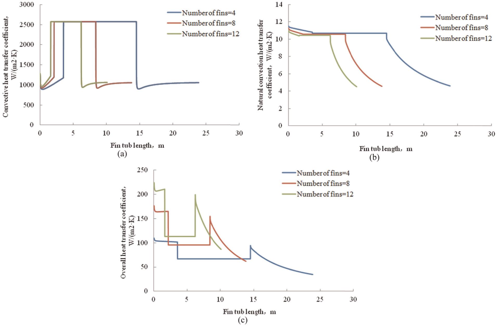
Effect of fin number on different parameters: (a) convective heat transfer coefficient, (b) natural convection heat transfer coefficient, and (c) overall heat transfer coefficient.
Figure 13(b) shows that with the increase in the number of fins, the natural convection of the air outside the tube heat transfer coefficient decreased, and the decrease rate is not very big, so the effect of increasing the number of fin tube air natural convection heat transfer coefficient is not very sensitive.
Figure 13(c) shows that with the increase in the number of fins, the total heat transfer coefficient of fin tube increases, and increases greatly, this is because the increase in the number of fin tube increases the heat transfer area, and the heat transfer of finned tube to enhance.
We can see from Figure 13, when the number of fins were 4, 8, and 12, the fin tube lengths were 23.88, 13.8, and 10.12 m, respectively, while from 4 to 8 when the amplitude is large, but from 8 to 12 when the change is not great, so we should choose the number of finned tube to be 8.
Conclusion
This research has analyzed the heat and mass transfer process and established the mathematical model based on MATLAB program, with which the required length of finned tube was calculated and analyzed. According to the actual cases, the reliability of the model was verified and we can popularize this method of analyzing into studies in relative fields.
This research has studied the effects of the air temperature, fin height, fin number, and LNG evaporation on the heat and mass transfer process, and calculated the required length of finned tube under different working conditions. According to the studies, the search has summed up that the heat transfer performance of finned tube increases with the increase in air temperature, fin height, and vaporization of LNG although the effects are not obvious. The research has also calculated that the total heat transfer coefficient of fin tube increases greatly with the increase in the number of fins. By comparing the outlet temperatures, the research summarizes that the most appropriate number of fins is 8.
Footnotes
Academic Editor: Jun Ren
Declaration of conflicting interests
The author(s) declared no potential conflicts of interest with respect to the research, authorship, and/or publication of this article.
Funding
The author(s) received no financial support for the research, authorship, and/or publication of this article.