
Abstract
In this article, a precooling cycle was used to reduce the power consumption and improve the heat transfer efficiency of a mixed refrigerant cycle. Propane precooling and mixed refrigerant precooling are two common precooling methods. The cascade dual mixed refrigerant cycle, which involves mixed refrigerant precooling and has a specific power consumption 10.9% lower than that of propane precooling, has been widely used. In order to analyze the relationships among precooling temperature, mixed refrigerant composition, and specific power consumption, the specific power consumption of a cascade dual mixed refrigerant cycle was investigated. A mixed refrigerant cooling temperature of 223 K, a precooling mixed refrigerant comprising C2H6–C5H12, and a subcooling mixed refrigerant comprising N2 and CH4–C3H8 yielded optimal results. In addition, a mixed refrigerant component ratio optimization model was established for the dual mixed refrigerant cycle. The results indicated that the optimum mixed refrigerant component ratios corresponded with the lowest levels of specific power consumption. Furthermore, by studying the effects of the feed gas pressure and temperature on the mixed refrigerant component ratios, the optimal operating conditions of the cascade dual mixed refrigerant cycle were determined to be 5.0 MPa and 298 K.
Introduction
The mixed refrigerant cycle (MRC), characterized by low power consumption, has been widely used in large liquefied natural gas (LNG) liquefaction plants. 1 This cycle is a patented technology developed by Air Products and Chemicals, Inc. (APCI) in the late 1960s. 2 By improving this cycle, APCI developed a propane-precooled mixed refrigerant cycle (C3/MRC), 3 which has become the most widely used refrigerant cycle technology. The production capacity of baseload C3/MRC LNG plants accounts for 87% of the total production capacity of LNG plants. In addition, Black & Veatch developed the PRICO®4 single-mixed refrigerant (SMR) process. The mixed fluid cascade process (MFCP) 5 developed by LINDE uses a mixed refrigerant for precooling in order to reduce the entropy and improve the heat transfer efficiency of MRCs with precooling and, thereby, improve the efficiency and scales of single production lines. In the dual mixed refrigerant (DMR) process 6 developed by Royal Dutch Shell, a mixture comprised of ethane, propane, and small amounts of methane and butane is used as the refrigerant for precooling. Using the DMR process, the precooling temperature of natural gas can reach −40°C with little processing equipment, improving flexibility. One DMR cycle, the Axens Liquefin TM Process 7 developed by IFP and Axens, uses a mixed refrigerant instead of propane for precooling. This process, with a production capacity as high as 400 × 104 t/a, can reduce production costs by 25% per ton of LNG.
Studies have indicated that the dual MRC has a specific power consumption 10.9% lower than that of the propane-precooled cycle, a low circulating mass of refrigerant, and a low water-cooling load. 8 In the cascade dual MRC, the precooling temperature determines the compositions of the precooling and subcooling mixed refrigerants. In addition, optimum precooling and subcooling mixed refrigerant component ratios are crucial for reducing power consumption. In this article, the precooling temperature and mixed refrigerant compositions were optimized in order to minimize the specific power consumption of the dual MRC. Then, the effects of the pressure and temperature of the feed gas on the optimum mixed refrigerant component ratios were discussed, and the optimized operating conditions of the cascade dual MRC were presented.
Theory
The cascade dual MRC is shown in Figure 1. 9 This cycle consists of a precooling MRC, subcooling MRC, and natural gas liquefaction loop. The effects of the precooling temperature, compositions of the precooling and subcooling mixed refrigerants, and pressure and temperature of the feed gas on the mixed refrigerant component ratios were studied using Figure 1. The component of natural gas is presented in Table 1.
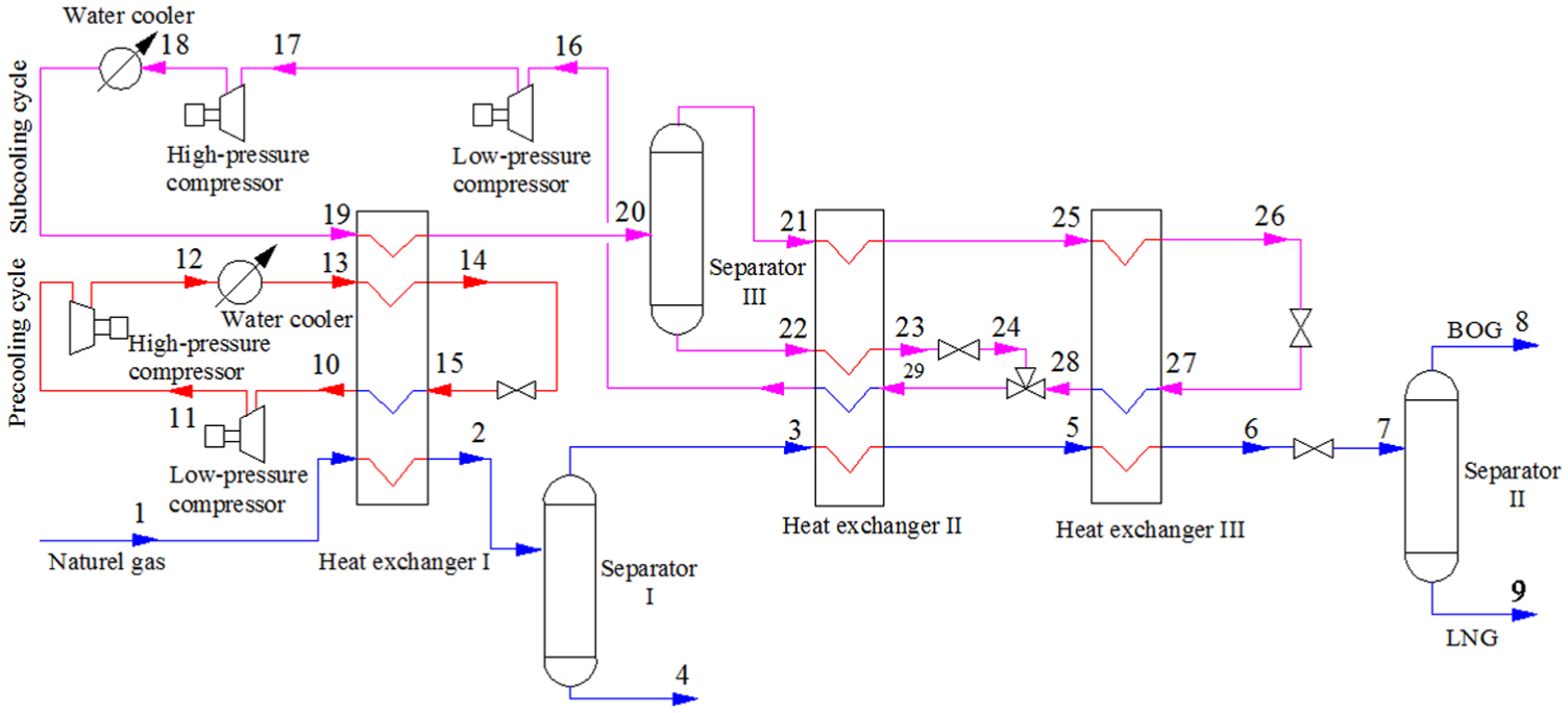
Cascade dual mixed refrigerant cycle.
The component of natural gas.

Precooling MRC
The mixed refrigerant was compressed to a pressure of 1500 kPa by the low-pressure and high-pressure compressors, cooled to 311 K by the water cooler, and precooled by heat exchanger I. Then, the mixed refrigerant was throttled backward, cooled, and returned to heat exchanger I. The resulting precooling mixed refrigerant, with a pressure of 160 kPa, was then returned to the low-pressure compressor and used to precool the natural gas and subcooling mixed refrigerant.
Subcooling MRC
The mixed refrigerant was compressed to a pressure of 2100 kPa by the low-pressure and high-pressure compressors, cooled to 311 K by the water cooler, further cooled by heat exchanger I, and then separated by separator III. After being cooled again by heat exchanger II, the liquid-phase mixed refrigerant was then throttled backward and further cooled. After being cooled by heat exchangers II and III, the resulting gas-phase mixed refrigerant was throttled backward and cooled again. Thus, the liquid-phase mixed refrigerant provided cooling for heat exchanger II, and the gas-phase mixed refrigerant provided cooling for heat exchangers II and III. The warmed mixed refrigerant, with a pressure of 170 kPa, was returned to the compressor where it was used for the subcooling MRC.
Natural gas liquefaction loop
The purified natural gas, with a pressure of 5000 kPa and a temperature of 293 K, entered separator I for heavy hydrocarbon separation after being precooled by heat exchanger I. The liquid phase entered the heavy hydrocarbon processing device. The gas phase was cooled by heat exchanger II, liquefied, and subcooled by heat exchanger III. Next, it was depressurized to a storage pressure of 120 kPa after being throttled backward. The natural gas then entered separator II for gas–liquid separation. The resulting liquid phase, LNG, was stored in a cryogenic tank.
In the following calculations, the efficiency of the mixed refrigerant compressors was equal to 80%, and the drops in the heat exchanger and water cooler fluid pressures were assumed to be negligible (ΔP = 0 kPa).
Method
Precooling temperature selection
The precooling temperature of a dual MRC directly affects the compositions and component ratios of its precooling and subcooling mixed refrigerants. The optimum precooling temperature was determined by defining the lowest specific power consumption (the lowest compressor power consumption per unit of LNG) as the objective function 10 and expressed as
where Wy denotes the compressor power consumption of the precooling MRC (kJ/h), Wc denotes the compressor power consumption of the subcooling MRC (kJ/h), and qLNG denotes the LNG flow rate (kg/h).
Using the objective function (equation (1)), the effects of the precooling temperature on the specific power consumption of the dual MRC were determined, as shown in Figure 2.

Effects of the precooling temperature on the specific power consumption of the DMR cycle.
As shown in Figure 2, the specific power consumption of the cycle decreased as the precooling temperature decreased. However, the specific power consumption decreased steadily at precooling temperatures lower than 223 K. Therefore, the precooling temperature of the mixed refrigerant in a dual MRC should be no lower than 223 K.
Composition of the precooling mixed refrigerant
In a dual MRC, precooling mixed refrigerant is used to precool the natural gas and subcooling mixed refrigerant. The minimum precooling temperature of the mixed refrigerant was 223 K. Once the cooling capacity supply was adequate, four precooling mixed refrigerant compositions were proposed and compared.
In Scheme I, the precooling mixed refrigerant was comprised of a molar ratio of C2H6:C3H8:i-C4H10:n-C5H12 = 29:51:17:3. This scheme was used as the basis of the other three schemes. In Schemes II, III, and IV, CH4, N2, and N2 and CH4 were added to the C2H6:i-C4H10:n-C5H12 = 29:17:3 molar ratio, respectively. In addition, the C3H8 contents of these schemes were altered in order to normalize their mixed refrigerant compositions:
Scheme I: C2H6, C3H8, i-C4H10, and n-C5H12;
Scheme II: CH4, C2H6, C3H8, i-C4H10, and n-C5H12;
Scheme III: N2, C2H6, C3H8, i-C4H10, and n-C5H12;
Scheme IV: N2, CH4, C2H6, C3H8, i-C4H10, and n-C5H12.
The specific power consumption of the DMR cycle with the four precooling mixed refrigerant composition schemes was calculated using the objective function (equation (1)). The effects of the four composition schemes on the specific power consumption are shown in Figure 3.

Effects of the precooling mixed refrigerant composition on the specific power consumption of the DMR cycle: (1) Scheme I, (2) Scheme II, (3) Scheme III, and (4) Scheme IV.
As shown in Figure 3, the mixed refrigerant comprising C2H6–C5H12 yielded the minimum specific power consumption at 223 K. The specific power consumption increased when a small amount of N2 or CH4 or small amounts of both N2 and CH4 were added to the mixed refrigerant. In addition, the specific power consumption increased as the N2 and CH4 contents increased.
Therefore, in order to minimize the specific power consumption of a dual MRC, the precooling mixed refrigerant should not contain N2 and CH4, but should be comprised of C2H6–C5H12.
Composition of the subcooling mixed refrigerant
The subcooling mixed refrigerant was used to liquefy and subcool the natural gas at temperatures ranging from 223 to 113 K. A mixed refrigerant should contain N2 and CH4 in order to yield subcooling mixed refrigerant cooling temperatures less than 113 K. Although the maximum cooling temperature of the subcooling mixed refrigerant (223 K) was higher than the cooling temperatures of C3H8, C4H10, and C5H12, 11 a moderate amount of C3H8 was added in order to reduce the compression work of the refrigerant, as shown in Figure 4:
Scheme I: N2, CH4, and C2H6;
Scheme II: N2, CH4, C2H6, and C3H8.

Effects of the subcooling mixed refrigerant composition on the specific power consumption of the DMR cycle: (1) Scheme I and (2) Scheme II.
In Scheme I, the mixed refrigerant comprised a molar ratio of N2:CH4:C2H6 = 3:25:22. This composition was used as the basis of Scheme II. In Scheme II, C3H8 was added to the N2:CH4:C2H6 = 3:25:22 molar ratio. The C3H8 content of Scheme II was altered in order to normalize the mixed refrigerant composition.
The specific power consumption of the DMR cycle with the two subcooling mixed refrigerant composition schemes was calculated using the objective function (equation (1)). The effects of the two composition schemes on the specific power consumption are shown in Figure 4.
As shown in Figure 4, the composition of the mixed refrigerant affected the compressor power consumption. Once the subcooling cycle cooling temperature was adequate, the addition of a small amount of C3H8 to the N2, CH4, and C2H6 mixture reduced the compressor power consumption of the refrigerant. For example, the addition of a 5% mole fraction of C3H8 reduced the power consumption by approximately 19.6%.
Therefore, in order to minimize the specific power consumption of a dual MRC, its subcooling mixed refrigerant should be comprised of N2, CH4, C2H6, and C3H8.
Case study
Mixed refrigerant component ratio optimization model
Objective function
The specific power consumption (J) was used as the objective function in order to measure the performance of the DMR cycle. Similarly, the minimum specific power consumption was used as the objective function of the mixed refrigerant component ratio optimization model, as shown in equation (1).
The compressor power consumption of the precooling MRC (Wy) was expressed as


The compressor power consumption of the subcooling MRC (Wc) was expressed as


In these equations, Wy1 represents the primary compressor power of the precooling cycle (kW), Wy2 represents the secondary compressor power of the precooling cycle (kW), Wc1 represents the primary compressor power of the subcooling cycle (kW), Wc2 represents the secondary compressor power of the subcooling cycle (kW), qymr represents the flow rate of the precooling mixed refrigerant (kg/h), and qmr represents the flow rate of the subcooling mixed refrigerant (kg/h).
In addition, H1–3 and H8–9 represent the total enthalpy of the material flow at nodes 1–3 and 8–9 of the natural gas liquefaction loop (kJ/h), respectively; H10 and H12 represent the total enthalpy of the material flow at nodes 10 and 12 of the precooling MRC (kJ/h), respectively; and H16 and H18–20 represent the total enthalpy of the material flow at nodes 16 and 18–20 of the subcooling MRC (kJ/h), respectively. The nodes are shown in Figure 1.
Furthermore, h3 represents the specific enthalpy of the material flow at node 3 of the natural gas liquefaction loop (kJ/kg); h10 and h12–13 represent the specific enthalpy of the material flow at nodes 10 and 12–13 of the precooling MRC (kJ/kg), respectively; and h16, h18, and h20 represent the specific enthalpy of the material flow at nodes 16, 18, and 20 of the subcooling MRC (kJ/kg), respectively. The nodes are shown in Figure 1.
The enthalpy of the mixed refrigerant was calculated as 12

where
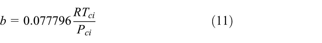


In these equations, R is the ideal gas constant, H represents the actual enthalpy (kJ/kg), Hid represents the ideal enthalpy (kJ/kg), Z is the gas compressibility factor, ω is the acentric factor, P represents pressure (kPa), T represents temperature (K), V represents volume (m3), and the subscripts c and r represent the critical and reduced states, respectively.
Variable optimization
The power of the compressors in the dual MRC was determined based on the enthalpy and flow rate of the refrigerant at the compressor inlets and outlets. The composition and component ratio of a mixed refrigerant affects its total and specific enthalpies. Therefore, the mixed refrigerant component ratio directly affects the specific power consumption of a DMR cycle once the precooling and subcooling mixed refrigerant compositions are determined.
According to the minimum specific power consumption, the optimized variables included a precooling mixed refrigerant component ratio comprised of Z(C2H6), Z(C3H8), Z(i-C4H10), and Z(n-C5H12), and a subcooling mixed refrigerant component ratio comprised of Z(N2), Z(CH4), Z(C2H6), and Z(C3H8).
Constraints
In a dual MRC, the heat transfer of the precooling and subcooling mixed refrigerants and natural gas occurs in the precooling heat exchanger, primary heat exchanger, and supercooling heat exchanger, respectively, satisfying the law of the conservation of energy. Therefore, the mixed refrigerant component ratio optimization constraints were expressed as 13


where the ΔTmin and ΔTLMTD of heat exchangers I, II, and III were necessary in order to satisfy the above constraints.
In these equations, ΔTmin and ΔTLMTD represent the minimum temperature difference and logarithmic mean temperature difference of the heat exchanger (K).
Optimization method
Some of the most commonly used optimization methods include black-box optimization, hybrid optimization, and sequential quadratic programming (SQP) optimization. SQP optimization, which has been recognized as one of the most effective optimization methods, can be applied to optimization problems with or without inequality and equality constraints. Therefore, due to the equality constraints on the mixed refrigerant component ratios of the dual MRC, the SQP optimization method was selected for the purposes of this article.
The objective function and constraints can be expressed as14,15

The SQP optimization comprised the following steps:
Equation (16) was substituted into equation (17), the quadratic programming problem, such that

An initial point (x(0)) and an initial matrix (Q(0) = I) were defined, and k = 0;
The quadratic programming problem was solved iteratively in order to obtain x(k);
If the termination criterion was satisfied, the output was ended; otherwise,
A linear search was conducted in order to determine the step size;
Assuming that
Optimization steps
The mixed refrigerant component ratio optimization calculations were performed using the HYSYS optimizer tool and the above optimization model. The steady-state physical properties were calculated using the P-R equation of state.
Independent variable selection
The mixed refrigerant component ratio was altered by adjusting the mole fractions of the various material flow components. Because the HYSYS optimizer tool was incapable of directly adjusting the mole fractions of the components, the material flow components were separated. The process conducted by HYSYS is shown in Figure 5.

HYSYS process.
Thus, as shown in Figure 6, the N2 and CH4–C5H12 flow rates of the precooling and subcooling cycles were defined as the independent variables for optimization.
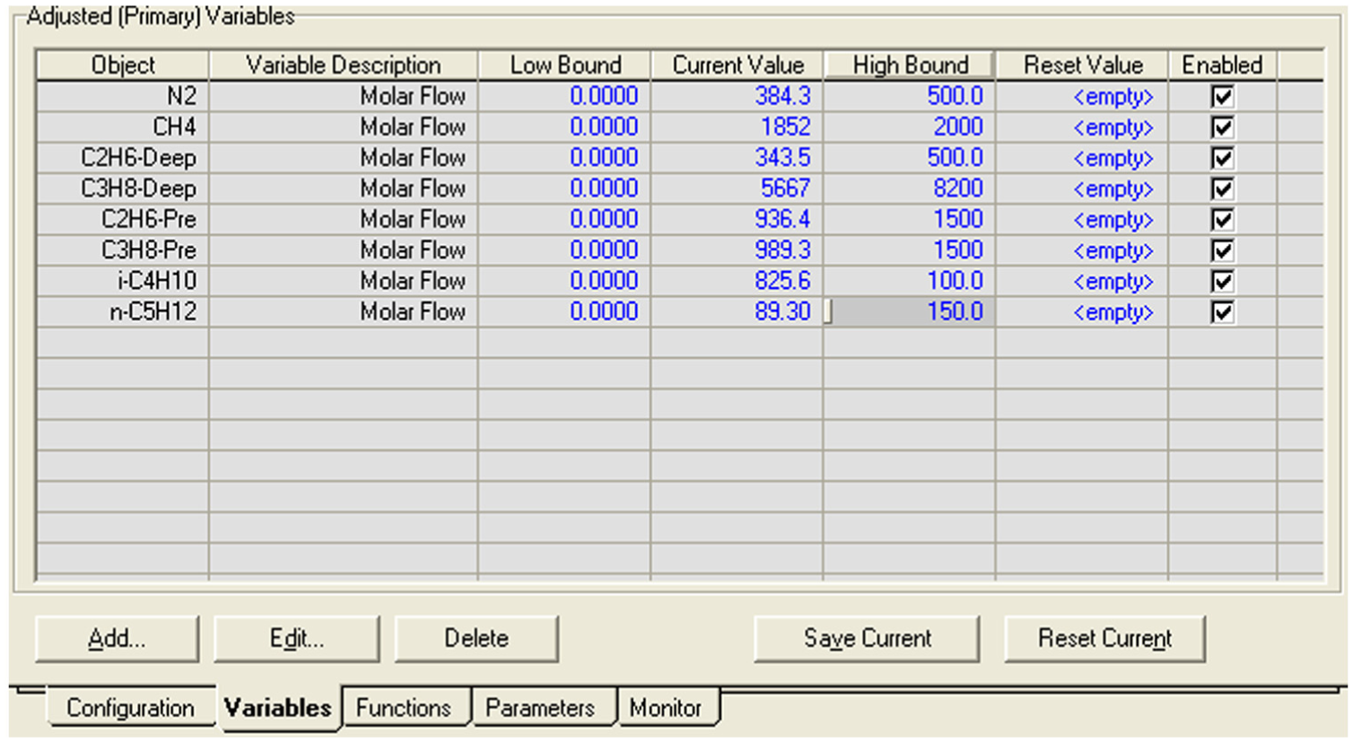
Variable optimization.
The material flows of the four pure components of the precooling and subcooling cycles were imported into the optimizer tool as variables. Reasonable high and low boundaries were defined. All of the objects were selected in order to adjust the independent variables.
Objective function and constraints
Using the optimization model, the specific power consumption was established as the objective function. The total power consumption of the cascade dual MRC was defined as the sum of the compressor power consumptions of the precooling and subcooling MRCs. The minimum temperature difference and logarithmic mean temperature difference of each heat exchanger were defined as the constraints. The objective function and constraints of the cycle were imported into the optimizer tool, as shown in Figures 7 and 8.

Spreadsheet data.

Objective function and constraints.
Optimization calculations
The HYSYS optimizer tool has five optimization algorithms, including the Fletcher Reeves, QuasiNewton, BOX, SQP, and Mixed algorithms. Based on the input mixed refrigerant component optimization model, HYSYS selected the SQP algorithm. The parameters, such as the tolerance, maximum iterations, and maximum change, were defined, as shown in Figure 9. The optimizer tool selected the auto-optimization function.

Optimization calculations.
The mixed refrigerant component ratio optimization calculations were performed under different operating conditions using the mixed refrigerant component ratio optimization model and the HYSYS optimizer tool.
Effects of the operating conditions of the feed gas on the mixed refrigerant component ratios
The effects of the feed gas pressure and temperature on the mixed refrigerant component ratios of the cascade dual MRC were analyzed using the HYSYS steady-state simulation tool.
Feed gas pressure
The temperature and flow rate of the feed gas were defined as 293 K and 100 × 104 Nm3/d, respectively. The effects of the feed gas pressure on the precooling and subcooling mixed refrigerant component ratios are shown in Table 2.
Mixed refrigerant component ratios at different feed gas pressures.

In addition, as the feed gas pressure changed, the precooling and subcooling mixed refrigerant component ratios also changed, resulting in changes in the minimum specific power consumption. The effects of the feed gas pressure on the specific power consumption of the DMR cycle with optimal mixed refrigerant component ratios are shown in Figure 10.

Effects of the feed gas pressure on the specific power consumption of the DMR cycle.
Feed gas temperature
The pressure and flow rate of the feed gas were defined as 5.0 MPa and 100 × 104 Nm3/d, respectively. The effects of the feed gas temperature on the precooling and subcooling mixed refrigerant component ratios were analyzed, as shown in Table 3.
Mixed refrigerant component ratios at different feed gas temperatures.

In addition, the specific power consumption of the cycle with optimal mixed refrigerant component ratios changed as the feed gas temperature changed. The effects of the feed gas temperature on the specific power consumption of the cycle are shown in Figure 11.

Effects of the feed gas temperature on the specific power consumption of the DMR cycle.
Results and discussion
As shown in Table 1, as the feed gas pressure increased, the N2 and C3H8 contents increased, and the CH4 and C2H6 contents decreased. In addition, as the feed gas pressure and subcooling mixed refrigerant component ratio changed, the precooling mixed refrigerant component ratio also changed, thereby minimizing the specific power consumption.
As shown in Figure 10, with optimum mixed refrigerant component ratios, the specific power consumption of the cycle initially decreased and then increased as the feed gas pressure changed. The minimum specific power consumption occurred when the feed gas pressure was equal to 5.0 MPa. Thus, the optimum feed gas pressure of the cascade MRC was defined as 5.0 MPa.
As shown in Table 2, the mixed refrigerant component ratios changed as the feed gas temperature changed. However, at feed gas temperatures higher than 298 K, the precooling and subcooling mixed refrigerant component ratios did not change.
As shown in Figure 11, the minimum specific power consumption occurred when the feed gas temperature was equal to 298 K. Thus, the optimum feed gas temperature of the cascade dual MRC was defined as 298 K.
Conclusion
The optimum cooling temperature of the precooling mixed refrigerant was 223 K. And the addition of N2 and CH4 to the precooling MRC increased its specific power consumption. Therefore, a precooling mixed refrigerant comprising C2H6–C5H12 without N2 and CH4was advised for use. The cooling temperature of the subcooling MRC ranged from 223 to 113 K. The highest subcooling temperature (223 K) was higher than the C3H8, C4H10, and C5H12 cooling temperatures. However, the addition of a moderate amount of C3H8 reduced the compressor power consumption of the refrigerant. Therefore, a subcooling mixed refrigerant comprising N2 and CH4–C3H8 was proposed for use. The optimum mixed refrigerant component ratios varied based on the pressure and temperature of the feed gas. However, neither the optimum precooling nor subcooling mixed refrigerant component ratios changed at feed gas temperatures higher than 298 K. The optimum operating conditions of the cascade dual MRC included a feed gas pressure and temperature of 5.0 MPa and 298 K, respectively.
Footnotes
Academic Editor: Jun Ren
Declaration of conflicting interests
The author(s) declared no potential conflicts of interest with respect to the research, authorship, and/or publication of this article.
Funding
The author(s) received no financial support for the research, authorship, and/or publication of this article.