
Abstract
This article presents architecture of integrated intelligent computer-aided design system for designing mechanical power-transmitting mechanisms (IICADkmps). The system has been developed in C# program environment with the aim of automatising the design process. This article presents a modern, automated approach to design. Developed kmps modules for calculation of geometrical and design characteristics of mechanical power-transmitting mechanisms are described. Three-dimensional geometrical parameter modelling of mechanical power-transmitting mechanisms was performed in the computer-aided design/computer-aided manufacturing/computer-aided engineering system CATIA V5. The connection between kmps calculation modules and CATIA V5 modelling system was established through initial three-dimensional models – templates. The outputs from the developed IICADkmps system generated final three-dimensional virtual models of mechanical power-transmitting mechanisms. Testing of the developed IICADkmps system was performed on friction, belt, cogged (spur and bevel gears) and chain transmitting mechanisms. Also, connection of the developed IICADkmps system with a device for rapid prototyping and computer numerical control machines was made for the purpose of additional testing and verification of practical use. Physical prototypes of designed characteristic elements of mechanical power-transmitting mechanisms were manufactured. The selected test three-dimensional virtual prototypes, obtained as an output from the developed IICADkmps system, were manufactured on the device for rapid prototyping (three-dimensional colour printer Spectrum Z510) and computer numerical control machines. Finally, at the end of the article, conclusions and suggested possible directions of further research, based on theoretical and practical research results, are presented.
Keywords
Introduction
Scope of research
In mechanical engineering, and generally in engineering, mechanical power-transmitting mechanisms are used more frequently than all other types of transmitting mechanisms. Designing of mechanical power-transmitting mechanisms, as complex mechanical systems, is a complex task requiring application of modern designing methods. The available time required for development of new designs is becoming shorter, which imposes the need for the designing process automatisation. Consequently, architecture of the integrated intelligent computer-aided design (IICAD) system for mechanical power-transmitting mechanism design, IICADkmps, with elements of artificial intelligence, was developed in the course of work.1,2
Summary of previous research
By examination of earlier research results, published papers covering issues of IICAD3–13 were observed and analysed. Such systems provide a high level of design process automatisation.
Purpose, methods and content of research
The purpose of the article, based on performed theoretical and practical research, was to develop an IICAD system providing a high level of automatisation of the mechanical power-transmitting mechanism design process. The system, based on the knowledge integrated into the model, processes data and makes decisions. During the development, effort was made to adjust the system to the needs of not only designers but also of students and pupils studying these issues.
During the IICADkmps system architecture development, object-oriented method of programming in computer language C# (∼5000 lines), as well as parameter approach in geometric modelling of three-dimensional (3D) virtual models of mechanical power-transmitting mechanisms was used. 2 3D virtual models were created using the FBD (features-based design) technique of solid modelling based on production characteristics. Parameters, essential for geometric modelling, are calculated within the developed kmps modules performing the calculation. Geometrical modelling parameter approach implies setup and creation of relational dependencies (formulas, laws and tables). The possibility to setup changes in certain parameter validities, in the form of functional mathematical and physical laws, is an important aspect of the technology aimed at formalisation of knowledge. This is particularly apparent in design of complex forms (e.g. gear tooth side). Using appropriate techniques,3,4,6,7,14,15 for the purpose of improving the technological level of computer application in the third stage of the design process (dimensioning and modelling), researches of possibilities of artificial intelligence incorporation into the developed system were carried out. With the aim to test and verify the carried out research, physical prototypes of the designed characteristic elements of mechanical power-transmitting mechanisms were made. Using 3D printing, as a method of rapid prototyping (RP), 16 physical prototypes were made from composites, whereupon physical prototypes were made of steel by computer numerical control (CNC) processing.
The researches were performed based on available findings and recommendations from scientific research literature, as well as standards and recommendations from renowned manufacturers of elements for power transmission (SKF, HPC and Ketten Fuchs).
The system is based on modular principles in order for the designer, in interaction with computer, to automatise performance of particular activities as much as possible. Owing to the implemented object-oriented programming method, artificial intelligence elements were built into the system.
After the creation of a catalogue from the generated final 3D virtual models of the elements of mechanical power-transmitting mechanisms, mounting and work simulation, the developed IICADkmps system was connected to the RP device and CNC machines and physical prototypes of designed characteristic elements of the mechanical power-transmitting mechanisms were created.
IICADkmps system architecture
The developed IICADkmps system uses a modern approach for calculating and modelling 3D virtual models of the mechanical power-transmitting mechanisms and for making of physical prototypes. It includes two integrated units:1,17–19
Developed kmps modules intended for the mechanical power-transmitting mechanism calculation (dimensioning);
Existing CAD/CAM/CAE (computer-aided design/computer-aided manufacturing/computer-aided engineering) system CATIA V5 on the market intended for geometrical modelling of 3D virtual models of mechanical power-transmitting mechanisms.20–23
The basic characteristics of the developed IICADkmps system are modularity, integrity, intelligence, collaborativity, competitiveness, interactivity, associativity, effectiveness and openness.
IICADkmps system
IICADkmps system architecture is very complex and heterogeneous. The system is developed on modular principle and allows the user (designer, student and pupil), with the computer support, to perform particular design activities. The basic task of the system is to provide integrated application of developed kmps modules/agents (knowledge-based systems or expert systems) to the user for the purpose of automatisation of certain activities when designing the mechanical power-transmitting mechanism. To this end, the software platform of the developed system relies on maximum application of available standards in the field of computer engineering, communication and data exchange.18,24
IICADkmps system consists of four integrated modules (Figure 1):
kmpsF – module for calculation and modelling of friction power-transmitting mechanisms;
kmpsRiK – module for calculation and modelling of belt power-transmitting mechanisms;
kmpsZ – module for calculation and modelling of cogged (spur and bevel) power-transmitting mechanisms;
kmpsL – module for calculation and modelling of chain power-transmitting mechanisms.

IICADkmps system architecture.
The obtained final 3D virtual model of the mechanical power-transmitting mechanisms is also used as the basis for creation of 3D element catalogue, mounting assemblies, movement simulation, rendering in real time, rapid prototyping on RP devices, production of parts on CNC machines, stress–deformation analysis using the finite elements method, drafting of technical documentation and so on.
IICADkmps system is installed as any other Windows application. The system, after installation, takes up 657 MB of memory space of HDD (hard disk drive) computer.
The developed IICADkmps system architecture is presented in Figure 1, and its interface is presented in Figure 2.

IICADkmps system interface.
Modules of the developed IICADkmps system consist of four linear connected parts: interface for input data setting, interface for geometrical design parameter calculation, interface for generation of reports on calculation results and interface for final 3D virtual model generation.
When the user sets the required input data, the system checks calculation criteria, performs calculation and informs the user about acquired output data. If all calculation criteria are not satisfied, the system informs the user that it is necessary to correct the set input data.
After successful calculation, the system also enables generation of report on calculation results in the form of Microsoft Word document (.docx).
If the result acquired by calculation is correct, the system proceeds with the final 3D virtual model generation. Their generation is performed in CATIA V5 system, based on initial models, by integration of adequate parameter values acquired by calculation from kmps module in the initial model trees.
Connection between kmps module for calculation and CATIA V5 system for mechanical power-transmitting mechanism modelling
The dynamic connection between kmps module for calculation and CATIA V5 system for mechanical power-transmitting mechanism modelling was obtained through initial 3D virtual models – templates. The initial models of the mechanical power-transmitting mechanisms were developed in CATIA V5 system. During the initial model development, parameter approach to modelling was applied, wherefore the parameters were integrated into the Parts or Products and Microsoft Excel tables. Application of parameter approach achieves better quality of products and shortens the process of modelling geometrically similar elements (families).
The final 3D virtual model generation (Figure 3) is accomplished by the following:
Change of parameters on initial 3D virtual model trees. Adequate parameters are changed directly on the tree of predefined initial models, giving them values acquired by calculation from kmps module. Initial models are updated and their transformation into final models, that is, final 3D virtual model generation, is almost instantaneous. This is possible only if parameter approach is used in modelling of initial models, by setting formulas, parameter laws and tables. After update, the final 3D virtual model corresponds to the model with dimensions acquired by calculation.
Choosing adequate configuration sets from Microsoft Excel tables. Values of dimensions needed for generation of final 3D virtual models are saved in Microsoft Excel tables (Design Table), which are used as database. Predefined dimensions of initial models are connected with the parameters saved in these tables. After establishing connections successfully, by selecting adequate configuration sets on the initial model trees, CATIA V5 system activates links towards these tables, ‘downloads’ adequate parameter values and integrates them into 3D models.

Final 3D virtual model generation procedure.
kmpsF and kmpsRiK modules
Because of the paper volume, only structure of kmpsZ and kmpsL (Figures 9–12, Tables 3 and 4) modules is presented in more detail. Structure of kmpsF and kmpsRiK modules, for which only interface for setting of transmitting mechanism characteristics with the calculation results (Figures 4 and 5) is presented, is developed analogously.
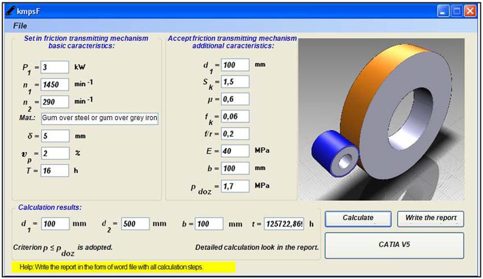
Setting of basic and adoption of extra characteristics of friction transmitting mechanism in kmpsF module and calculation results.

Setting of belt transmitting mechanism characteristics in kmpsRiK module and calculation results.
kmpsZ and kmpsL modules
Cogged transmitting mechanisms present variants of construction solutions, consisting of cogged executors of elementary functions. They are applied in most of mechanical systems with wide structure variation. They consist of parts and assemblies of variant shape and most of them are standardised or with standardised parameters. Key decisions refer to the selection of structure variant, standard parts, dimensions and materials. In this context, when designing cogged transmitting mechanism, application of the integrated intelligent system connecting all stages of the designing process is the most favourable.
kmpsZ module consists of two integrated submodules for cogged transmitting mechanism calculation, and they are as follows:
With straight spur gears;
With straight bevel gears.
Based on working, design and technological characteristics, calculation defines gear module and then its geometrical dimensions. The selection of material of driver gear is made from the descending menu, from the standard materials base, whereby their characteristics are set automatically after the selection.
Interface for setting characteristics of cogged transmitting mechanism with straight spur gears is presented in Figure 6.

Setting of cogged transmitting mechanism with straight spur gear characteristics in kmpsZ module and calculation results.
After the user sets correct input data, by clicking the button  , kmpsZ module performs the calculation and shows the calculation results (Figure 6). For the purpose of having insight into complete calculation, the report needs to be generated by clicking the button
  .
.
When the calculation results are obtained, by clicking the button  , the initial model of cogged transmitting mechanism is started in CATIA V5 system, and the adequate parameter values obtained by calculation are integrated into their tree (Figure 7).

Overview of parameters on the tree of spur gear 3D virtual model in CATIA V5 system used for geometry control.
The initial model updating and its transformation into the final assembly model, that is, generation of final 3D virtual model of cogged transmitting mechanism with spur gears, are performed almost immediately (Figure 8, Tables 1 and 2).

Final 3D virtual model of drive and driven straight spur gear.
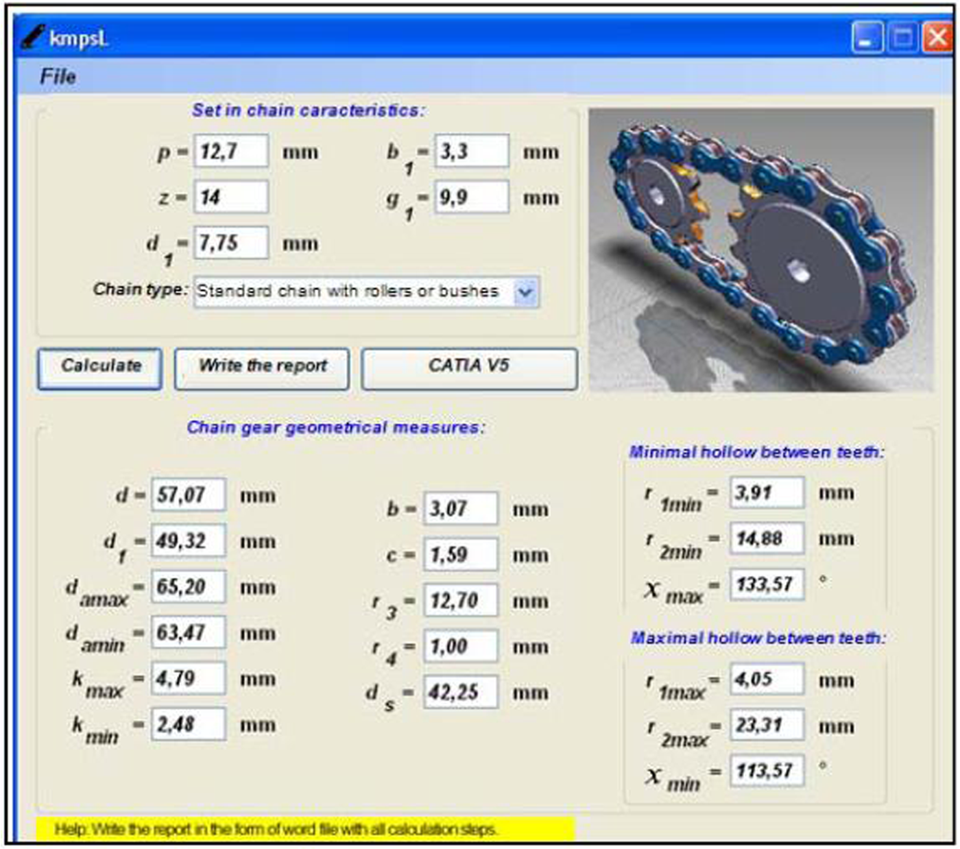
Setting of chain transmitting mechanism characteristics in kmpsL module and calculation results (drive chain gear).

Connection between initial model dimensions and parameters saved in Microsoft Excel table.
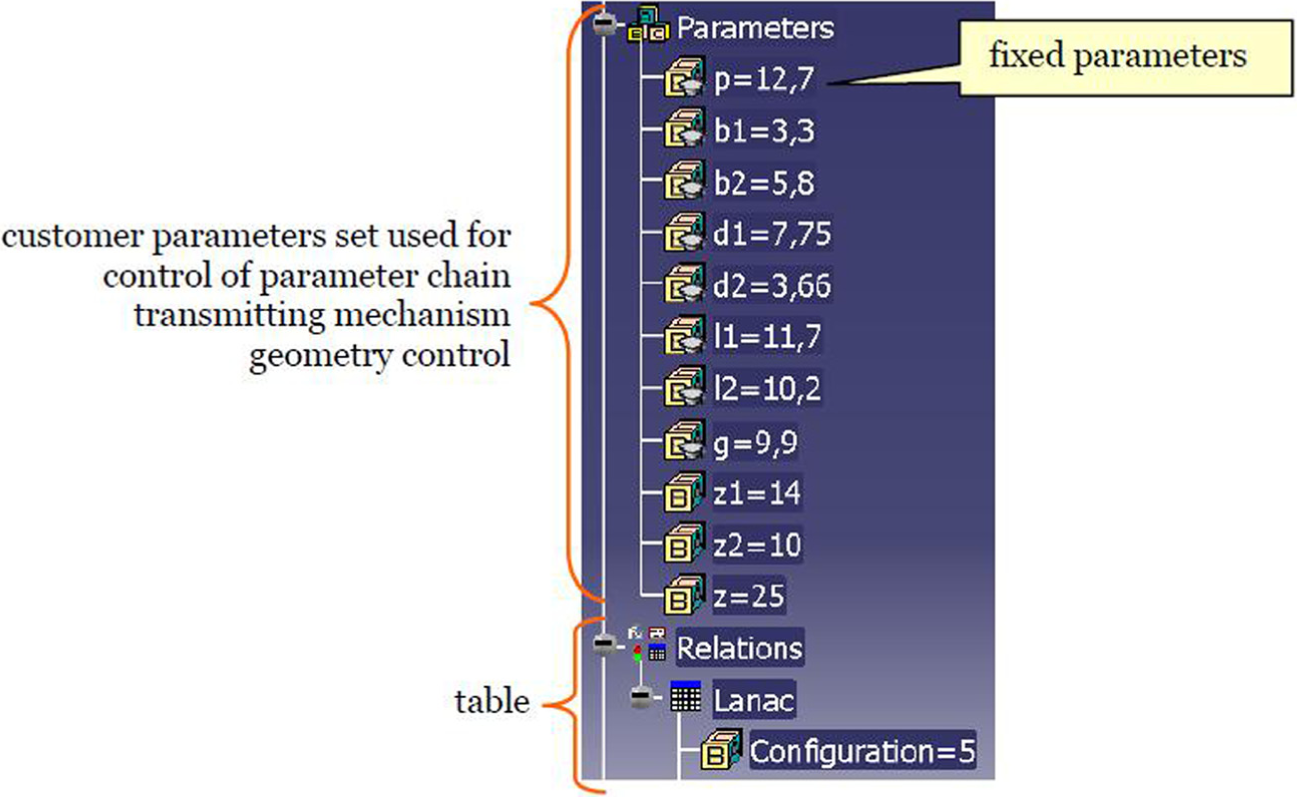
Overview of parameters on the tree of chain transmitting mechanism 3D virtual model in CATIA V5 system used for geometry control.

Final 3D virtual model of drive and driven chain gear for chain with rollers.
Parameters and formulas of spur and bevel gears.
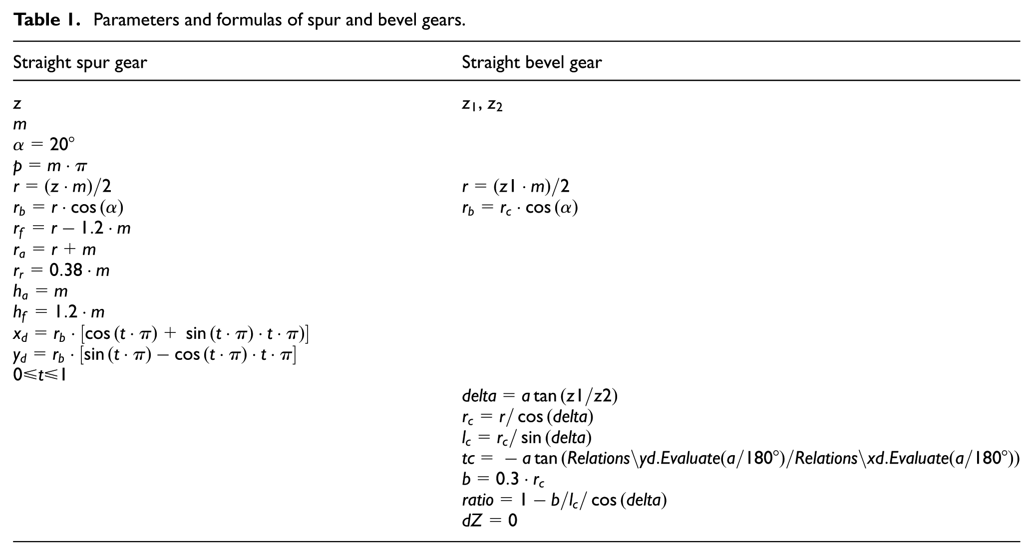
Straight spur gear parameters.

Chain gear parameters and formulas.

Chain gear parameters.

Catalogue creating, mounting and work simulation
Since CATIA V5 system includes the catalogue of only particular standard mechanical elements, in industrial application of the developed IICADkmps system, it is recommended to expand the catalogue with remaining 3D elements necessary for modelling mechanical power-transmitting mechanisms.
There are two methods for creating the catalogue of 3D elements, and they are as follows:
Based on initial parts – templates, using tables designed in Microsoft Excel, families of geometrically similar parts are created;
By inserting geometrically different parts in the catalogue.
3D modelling of particular elements (positions) of mechanical power-transmitting mechanisms was performed in Sketcher, Part Design and Generative Shape Design CATIA V5 system modules. 3D element catalogue was created using CATIA V5 system Catalog Editor module workbench. 20
When the catalogue is created, 3D elements can be multiplied to create a desirable structure of mechanical power-transmitting mechanism.
3D virtual model positions were mounted into assembly block in CATIA V5 system Assembly Design module. 20
Work simulation of the mechanical power-transmitting mechanisms, that is, movement simulation of their components, was carried out in CATIA V5 system Digital Mockup (DMU) Kinematics module. 21
Rendering in real time of final 3D virtual models of mechanical power-transmitting mechanism was performed in 3DVIA Composer software.
Verification of practical application of IICADkmps system
After performed research, with the aim to additionally test and verify practical application, the developed IICADkmps system was connected with the device for making rapid prototypes and with CNC machines. Physical prototypes of the designed characteristic elements of mechanical power-transmitting mechanisms were made. The basis for the making of the physical prototypes was 3D virtual prototypes of the mechanical power-transmitting mechanism elements, obtained as an output from the developed IICADkmps system.
Physical prototype making on RP device
The selected test 3D virtual prototypes, obtained as an output from the developed IICADkmps system, were manufactured on the device for the making of rapid prototypes (3D colour printer Spectrum Z510). This way, physical prototypes of characteristic elements of the mechanical power-transmitting mechanisms were made from composites (zp150 and zp151 powder, zb60 binder).
Information about the 3D virtual model geometry, from work station to Spectrum Z510, was processed by ZPrint software (Figure 13).

Course of RP prototype making process and their impregnation.
Comparison between 3D virtual prototypes created by IICADkmps system and physical prototypes made on RP device Spectrum Z510 is presented in Table 5.
Comparative overview of 3D virtual and physical RP prototypes.

3D: three-dimensional; RP: rapid prototyping.
Physical prototype making on CNC machines
After testing the developed IICADkmps system on RP device, its industrial application on CNC machines was tested. The selected test 3D virtual prototypes, obtained as an output from the developed IICADkmps system, were made on appropriate CNC machines. This way, physical prototypes of characteristic elements of the mechanical power-transmitting mechanisms were made of steel 11SMnPb30.
Information about the 3D model geometry, from work station to CNC machines, was processed by appropriate post-processors (Figure 14).

Course of CNC prototype making process, on the example of pulley R3-80: (a) 3D virtual prototype, technologic operations definition, (b) 3D tools moving simulation, post-processing, CNC program generation, (c) 3D treatment video simulation in real time, (d) making on CNC machines and (e) physical CNC prototype.
Comparison between 3D virtual prototypes created by the IICADkmps system and physical prototypes made on CNC machines is presented in Table 6.
Comparative overview of 3D virtual and physical CNC prototypes.

3D: three-dimensional; CNC: computer numerical control.
Conclusion and further research
Intelligent systems differ from conventional systems. Conventional systems cannot process knowledge, wherefore they are applied in a designing process that includes iterative and routine activities. Unlike these, intelligent systems are based on artificial intelligence techniques and include modules which can process knowledge, wherefore they may be used in all stages of the designing process.
Based on analysis of research results and verification of practical application of the developed IICADkmps system, it may be concluded as follows:
Implementation effects of IICADkmps system, as designing process supports, are as follows: much better product quality; much shorter time of designing process (up to 50% compared to conventional system application, depending on product complexity); much lower design process costs (up to 90% compared to conventional designing, depending on product complexity and applied means); company with its products becomes more competitive on the domestic and international market.
Building segments of IICADkmps system are modules for calculation and modelling: friction, belt, cogged (spur gears and bevel gears) and chain power-transmitting mechanisms.
kmps modules intended for calculation are connected with CATIA V5 system for modelling with the aim of automatising the designing process.
Connection between kmps module and CATIA V5 system is made through initial 3D virtual models.
Developed IICADkmps system may be successfully connected with RP devices and CNC machines for making of physical prototypes.
The result of IICADkmps system application is 3D virtual prototypes, or physical prototypes made on RP devices and CNC machines, of elements of the mechanical power-transmitting mechanisms.
In order to expand the IICADkmps system, establishment of subsystem for concept development and subsystem for analysis and optimisation of the mechanical power-transmitting mechanisms is recommended.
Footnotes
Appendix 1
Acknowledgements
Physical prototypes on RP devices were made by the 3D Systems company and IB-PROCADD, Slovenia. Physical prototypes on CNC machines were made by the Alatnicar CNC company, Croatia.
Academic Editor: Yong Chen
Declaration of conflicting interests
The author(s) declared no potential conflicts of interest with respect to the research, authorship and/or publication of this article.
Funding
The author(s) received no financial support for the research, authorship and/or publication of this article.