
Abstract
Low rigidity of industrial robot can easily result in deformations during grinding process and finally lead to a deviation between planned path and actual path. In order to reduce impact of the deviation, with an analysis of the relationship among feed velocity, deformation, and trajectory planning, a deformation-based trajectory optimization approach is proposed in this article. The relationship among grinding angle, feed velocity, deformation, and interpolation point planning is first studied and two velocity constraints are proposed. The positions of interpolation points are then adjusted in accordance with the velocity constraints to optimize trajectory. Experiment results indicate that the proposed trajectory optimization approach can significantly reduce the deformation and vibration occurring in robotic grinding process.
Introduction
Robotic machining has attracted attentions of scholars and many studies on robotic machining application are found.1–4 Yet few researches on trajectory planning can be found and current studies are mostly focused on robot system integration and force control. This might be due to a misconception that robot grinding path planning and numerical control (NC) path planning are similar. 5 With an analysis of industrial robot structure, Hu and Chen 6 proposed a grid-set model for rough machining to improve the robot grinding trajectory planning. In their later research, errors caused by overcut and undercut operations are analyzed to develop a curvature-machining algorithm and finally come to a trajectory planning method. 7 Olabi et al. 8 proposed a feed rate planning method by generating a jerk limited to smooth continuous machining with an industrial robot. On the other hand, Lin and Lu 9 discussed influence of abrasive orientation on robotic machining quality and proposed a robot grinding trajectory planning method under consideration of singular points and joint constraints. The equal chord deviation fitting method and equal scallop height method, which are commonly used in computer numerical control (CNC) path planning, were developed for robot trajectory planning by Zhang et al. 10
However, the researches above are mostly concerned with the characteristics of the robot structure and control system, while the impact of low rigidity on path planning is neglected. Liu et al. 11 stated that the machining quality is considerably sensitive to robot rigidity. To identify the impact of low rigidity on robot deformation, Zhang et al. 12 constructed a robot static rigidity model, identifying the coupling relationship between Joint rigidity and Cartesian rigidity, and established an online compensation model for robotic machining process. However, robot machining is a dynamic process and impacted by workpiece curvature or evenness, cutting angle, abrasives evenness, feed rate, and so on. The robot static rigidity model is not capable to cover such complicated and dynamic process. In view of this, Persoons and Vanherck 13 educed a robot grinding dynamic model and then validate the model by analyzing machining force acting on uneven workpiece. Rafieian et al. 14 studied force fluctuation occurring in rigid plane grinding process to indicate the coupling relationship of abrasive rotating speed, abrasive flatness, and fluctuation frequency of vibration. A nonlinear rigidity model of robotic grinding system is then constructed to evaluate the influence of grinding vibration on machining precision.
According to the discussion above, robotic rigidity performs a significant role in machining quality. Although substantial research on robotic applications is found, few of them are concentrated on the impact of robotic deformation on trajectory planning. Different splines are used in trajectory planning, including cubic splines, trigonometric spline, and B-spline.15–17 With the use of B-spline, smooth curves can be obtained among available interpolation types with no overshoot. Any given spline function can be expressed as a linear combination of B-splines of that degree. B-spline is widely used in product design and studies on B-spline trajectory planning are found.18–20 Ozaki et al. 21 proposed a learning control algorithm with B-spline, which consists of a global learning process and a local learning process, to improve trajectory planning. To compensate for the tracking error caused by external load, Biagiotti et al. 22 proposed a control scheme using dynamic filters for the B-spline trajectory planning.
This article aims to identify the deformation caused in machining process and propose a trajectory optimization approach with respect to velocity constraints. The B-spline curve, taken as an example, is first introduced to illustrate the conception of interpolation planning and velocity constraints. The potential influenced caused by robotic deformation on trajectory planning is identified as well. The grinding mechanism is then analyzed to indicate the coupling relationship of grinding parameters, deformation and vibration, and robot stiffness, on the basis of which the grinding dynamic model is constructed as well as the velocity constraints and interpolation planning approach. Grinding simulations and two kinds of experiments, including inclined experiments and experiment on B-spline curve, are subsequently conducted to verify the proposed model the validity of interpolation planning approach.
Interpolation planning and velocity constraint
Trajectory planning is a process to obtain the coordinate of intermediate point according to trajectory equation and known data. Before discussing the influence of deformation on trajectory planning, it is essential to understand the conception of interpolation and velocity constraint. In this section, B-spline is taken as an example to illustrate the realization process of interpolation planning and velocity constraint.
B-spline
With the characters of the convex hull, local support, and geometrical invariability, the B-spline curve is considered as an effective design method and widely used in automobile, aircraft, and other industries. To obtain the interpolation point position and velocity planning of B-spline curve, the concept of B-spline curve is introduced.
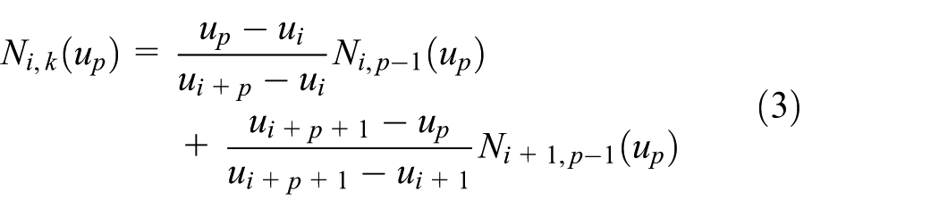
The B-spline curve is composed by the control point and B-spline basis function. The relationship of control points and the B-spline curve is shown in Figure 1, and the formula can be expressed as

where k is the order of B-spline curves;


B-spline curve.
Interpolation planning for B-spline curve
According to equations (1)–(3), as the value of

where
Interpolation planning based on velocity constraint
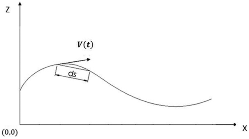
To achieve path planning by limiting velocity, it is important to identify the relationship to velocity

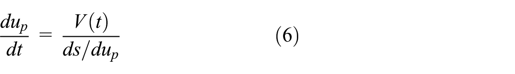
where displacement ds can be obtained by

where x and z can be calculated by

B-spline trajectory velocity planning.
The relationship between up and V(t) can be obtained by substituting equations (7) and (8) into equation (6).
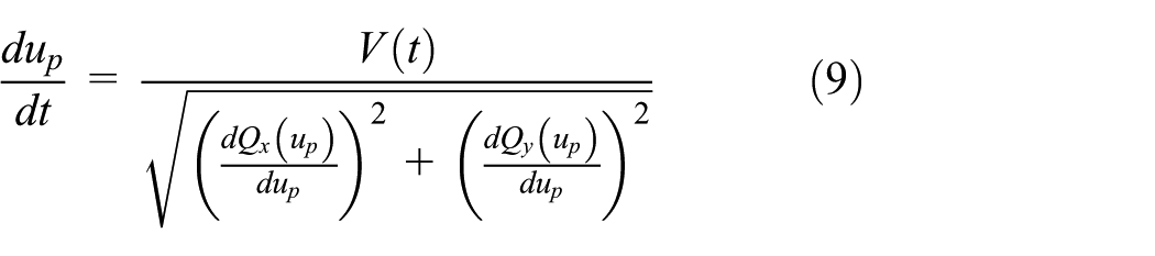
Substituting equation (9) into equation (4) to obtain interpolation planning method based on velocity constraint
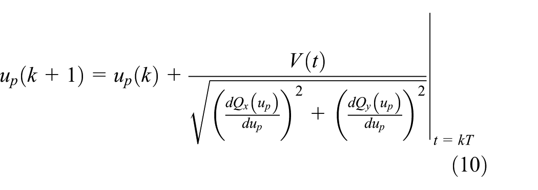
When using time division interpolation method, the interpolation period of robotic system is constant. The feed velocity of robot in each interpolation period is determined by corresponding required displacement. According to equation (1), when robot moves along B-spline curve
Robotic grinding dynamic analysis
When performing grinding, the low stiffness of robotic system can easily result in deformation and vibration caused by dynamic force acting on end effector and consequently impacted on the actual grinding depth and surface quality. This chapter first analyzed the generation and release of deformation to construct grinding dynamic model and to identify the problem for trajectory planning caused by grinding deformation. The exact influence is then studied by exploring the relationship of grinding angle, feed rated, deformation, and grinding force, and the related deformation and vibration formulas are developed as well.
Grinding dynamic
Due to open-loop and serial structure, the stiffness of robot is lower in comparison with CNC machine, and it is easy to deform during machining operations. As shown in Figure 3, abrasive moves towards workpiece at a feed speed of

where K is equivalent stiffness of robot grinding system. Actually, the deformation


Deformation generation.
The deformation

Deviation between planned path and actual path.
Deformation analysis
After a preview of the influence of deformation on trajectory planning, this section further studies the exact generation process of deformation to explore the relationship between grinding angle, feed rate, deformation, and vibration. As shown in Figure 5(a), the abrasive conducts grinding operations on workpiece with a feed speed


Grinding analysis.
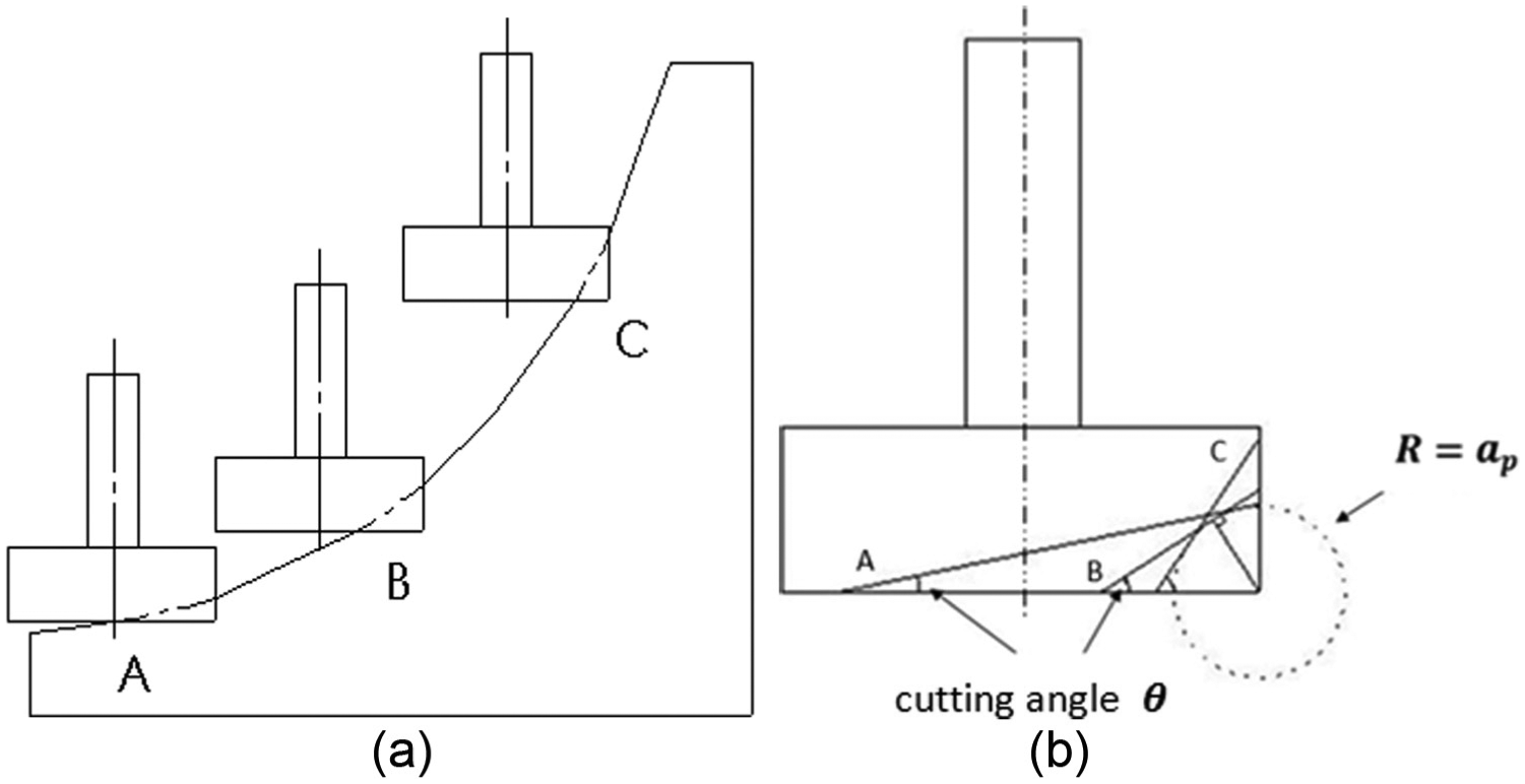
In addition, grinding angle also plays a considerable role in actual grinding process. As shown in Figure 6, according to grinding angle

Influence of velocity on grinding.
According to the discussion above, removal rate is one of the key factors to grinding error. When other technical parameters are fixed, the removal rate

where

In actual grinding process, the effective grinding area varies along with grinding angle

while

Change of effective grinding area: (a) surface trajectory and (b) grinding area.
As shown in Figure 8, the back half shaft part of abrasive (graphic EDC) does not participate in actual grinding and the front half shaft part of abrasive (graphic ABCD in shadow) is considered as the effective grinding area.
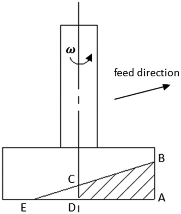
Calculation of effective grinding area.
Therefore, the relationship between

Substituting equation (18) into equation (13)

According to grinding theory, the grinding force is impacted by effective grinding area

Therefore, in accordance with equations (15) and (20), it can be induced that when the grinding depth is constant, the variation of grinding angle will impact the value of grinding force and removal rate. Furthermore, a statement can be made that for curve surface grinding, constant grinding force does not mean isobathic grinding.
Vibration analysis
Grinding vibration includes impact vibration and chatter. The grinding vibration amplitude A can be calculated by

while


while

Substituting equation (18) into equation (24)

Interpolation for robotic grinding
Velocity constraint with respect to deformation
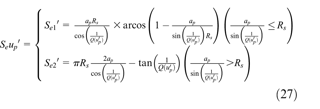
In grinding process, since the variation of grinding angle

Substituting equation (26) into equation (18)
And the variation of machining error can be obtained by substituting (27) into equation (19)
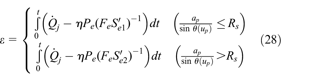
Setting upper bound of machining error as

And the velocity constraint can be written as

Velocity constraint with respect to vibration
According to equation (21), the relationship between roughness requirement

Substituting equation (27) into equation (25)
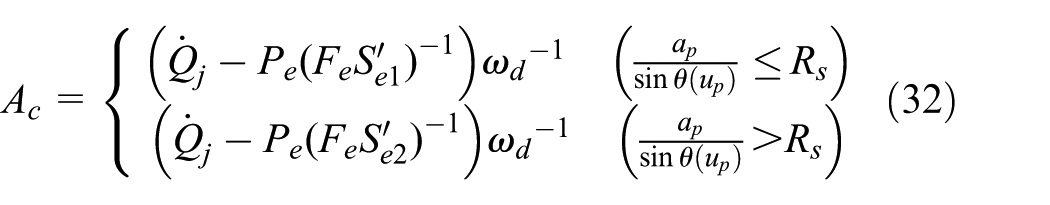
And the upper bound of impact vibration amplitude is

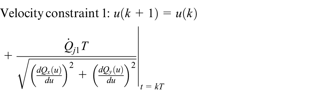
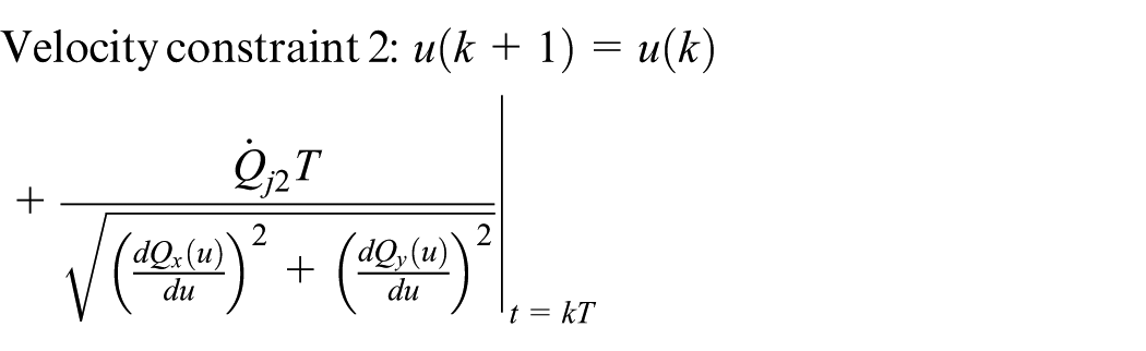
The velocity constraints can be obtained by separately substituting equations (30) and (33) into equation (10)
Curve surface grinding simulation
Before conducting experiments, the grinding simulations are carried out to observe the behavior of grinding deformation and provide data reference to the later experiments. In order to completely evaluate the influence of grinding angle vibration on deformation, a quarter workpiece is used as the simulation object as shown in Figure 9(a), while the grinding direction and path are shown in Figure 9(b). The parameters of simulations are feed rate

Simulation object and grinding trajectory.
Two simulations are conducted. Simulation 1 is carried out to observe the relationship between grinding angle and deformation, while the other aims to explore the impact of velocity on deformation. The results of simulation 1, of which the grinding angle changes from 0° to 90°, are shown in Figure 10. The change of effective grinding area

Results of simulation 1 (grinding angle variation).
In order to observe the impact of feed rate on deformation, the settings of simulations are grinding angle

Results of simulation 2 (feed rate variation).
Robot grinding system and experiments
Robot grinding system
The robotic grinding system used for experiment is composed of Cartesian coordinate robot, expended rotating platform, force sensor, grinding tool, and workpiece. As shown in Figure 12, the robot grinding system, consisting of Cartesian coordinate robot and expended rotating platform, has an open-loop and serial structure. The serial structure is similar to general industrial robots. Therefore, it can illustrate the rigidity behavior of general industrial robots. The force sensor and grinding tool are installed on the end of Z-axis, while the workpiece is installed on the rotating platform.

Robot grinding system 1: Cartesian coordinate robot; 2: expended rotating platform; 3: force sensor; 4: grinding tool; 5: workpiece.
Grinding experiment
Two kinds of experiments are conducted, including experiments on beveled workpiece and experiment on curved surface workpiece. The experiments on beveled workpiece aim to verify the relationship of grinding angle, feed rate, deformation, and vibration, while the other is to evaluate the efficiency of the interpolation proposed.
Experiment on beveled workpiece
According to simulation results, the removal rate
Experiment 1 (grinding angle: 10°, as shown in Figure 13(a))

(a) Grinding angle, (b)
The grinding angle of experiment 1 is 10°, and the other settings are listed in Table 1. After being processed by the filter, the experiment results are shown in Figure 13(b)–(f). When the feed rate is 0.3 mm/s, the average grinding force is 1.1 N and the force fluctuation is around 3 N. As the feed rate increases from 0.6 to 1.5 mm/s, the average of grinding force raises from 1.5 to around 2.5 N, while the force fluctuation has a considerable increase around 5 N. The trend of deformation, as shown in Figure 13(g), is similar to the grinding force. The relationship between velocity and deformation is nonlinear. This may be due to the grinding efficiency
Grinding parameters for experiment 1.
Experiment 2 (grinding angle: 30°, as shown in Figure 14(a))
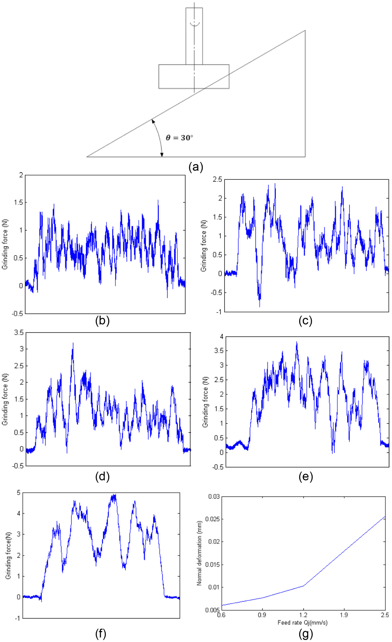
(a) Grinding angle, (b)
The grinding angle of experiment 1 is 30°, and the other settings are listed in Table 2. After being processed by the filter, the experiment results, as shown in Figure 14(b)–(f), are similar to the ones in experiment 1. It is important to note that the sensitivity of grinding force to velocity in experiment 2 is less than the one in experiment 1. As the feed rate increases from 0.6 to 2.5 mm/s, the average value of grinding force increases from 0.7 to 2.5 N. It is important to note that the average force of feed rate of 1.5 mm/s in experiment 1 is around 2.5 N, which is similar as the one of feed rate of 1.9 mm/s in experiment 2. Although the average forces are similar, the corresponding normal deformations are different, which are 0.012 and 0.017 mm. One of the reasons for this situation is that as the grinding angle increases from 0° to 90°, the component of force in normal direction increases and has a greater influence on normal deformation.
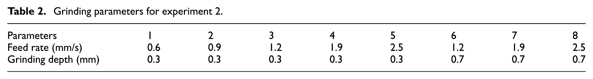
Grinding parameters for experiment 2.
According to the previous experiments, the sensitivity of grinding force to velocity is not obvious enough when the grinding depth is 0.3 mm. In order to provide a comparison to the following experiments, the grinding depth is increased to 0.7 mm and extra experiments are conducted as shown in Figure 15. The grinding force dramatically increases as the feed rate increases from 1.2 to 2.5 mm/s. The average of grinding force increases from 5 to 11 N, while the amplitude of fluctuation increases from 4 to 8 N.
Experiment 3 (grinding angle: 40°, as shown in Figure 16(a))

(a)

(a)
The grinding angle of experiment 1 is 40°, and the other settings are listed in Table 3. The experiment results are shown in Figure 16(b)–(f), which is also similar to the ones in experiments 1 and 2. As feed velocity increases from 0.3 to 0.7 mm/s, the average of grinding force increases two times, from 1.8 N at a feed rate of 0.3 mm/s to 4 N at a feed rate of 0.7 mm/s. The amplitude of force fluctuation increases from 2.5 to 5.5 N. The corresponding deformations are 0.018, 0.035, and 0.042 mm.
Grinding parameters for experiment 3.

Experiments on B-spline curved surface
The aim of this research is to optimize trajectory planning by implementing velocity constraints and interpolation planning. Therefore, B-spline curved surface workpiece is used as a grinding object in this experiment. The exact shape of the workpiece is shown in Figure 17. In order to evaluate the efficiency of the proposed approach, an experiment on curved surface without respect to any constraint is conducted as a comparison object. The parameters are

B-spline curved surface.

Experiments on B-spline curved surface: (a) without constraints and (b) with constraints.
Conclusion
Since the robotic deformation and vibration are considerably sensitive to the change of grinding angle and feed velocity, this article proposed a deformation-based trajectory optimization approach based on the relationship among feed velocity, deformation, and trajectory planning. The relationship among feed velocity, deformation, and trajectory planning is first studied and two velocity constraints are deduced. With the use of velocity constraints, positions of interpolation points are adjusted to optimize robotic grinding trajectory. Experiment result indicates that the deformation-based velocity constraints and trajectory optimization approach proposed in this article can considerably reduce the deformation and vibration. Many studies focus on compensation for deformation by force control. Only few of them explored the impact of low rigidity of robot on trajectory planning. This study can provide a reference to later research.
Future works
Grinding is a complicated process and influenced by many factors. To construct the exact model of robotic grinding, substantial data are required. Therefore, this article studied the relationship of feed rate, grinding angle, stiffness, and deformation, while the other factors, for example, vibration frequency and rotate speed are not discussed in this article. According to previous research and traditional grinding model, the relationship of vibration frequency, feed rate, stiffness is considerable, which can be studied in further research.
Footnotes
Handling Editor: David R Salgado
Declaration of conflicting interests
The author(s) declared no potential conflicts of interest with respect to the research, authorship, and/or publication of this article.
Funding
The author(s) disclosed receipt of the following financial support for the research, authorship, and/or publication of this article: This project is sponsored by National Science and Technology Major Project of China (no. 20152X04005006), Science and Technology Planning Project of Guangdong Province, China (nos. 2014B090921004, 2014B090920001, 2015B010918002), Science and Technology Major Project of Zhongshan city, China (no. 2016F2FC0006).