
Abstract
The universal joint is one of the most critical parts of both the engine and the transmission system of a vehicle. After long-term use, however, some vibration and abnormal noise might occur in it, which may lessen safety while driving. In this article, we investigate faults associated with the double cross universal joint, including looseness, wear, and intermediate shaft torsional deformation. First, we propose a transmission model and a new fault model for this joint. Then, the model parameters of the optimal transmission performance are analyzed. Finally, the main contribution of this article is in discussing the transmission performance as related to looseness, wear, and the intermediate shaft torsional deformation. Our results show that when the angle of the two universal joints is consistent, the phase angle equals 90 and the angular velocity of the output shaft becomes constant, which indicates an optimal transmission performance. When the universal joint is exhibiting looseness, the performance of the angular velocity of the output shaft and the transmission becomes worse as the looseness increases. For both wear and the intermediate shaft torsional deformation, the output angular velocity is also unstable. If looseness occurs at the same time as one of these two faults, the instability will be superimposed and the transmission performance will be even worse. This article provides reference for analysis of faults of the universal joint and its diagnosis; for example, it provides suggestions for when the universal joint should be inspected for repairs or replaced.
Keywords
Introduction
The rapid development of the automobile industry and the high expectations of drivers has meant that better driving experiences have become the goal of the automobile industry; they need to provide cars that drive well, are comfortable, and are easy to control.1–3 In recent years, the manufacturing industry technologies of parts used to build vehicles have developed rapidly due to the pursuit of both lightweight materials and quiet and energy-efficient engines.4,5 The universal transmission system is an important part of any vehicle and needs to be considered during the design process. The most critical part of this system is the universal joint, as it is used in the engine and steering system. 6 It is important to design it with consideration to its strength, durability, noise, and efficiency. 7
The cross shaft universal joint is used for the power transmission when the input and output shaft are not on the same line, is one of the main components of the vehicle transmission system. 8 It has a number of advantageous features, such as its simple structure, low wear, high transmission power, and it can bear a large load and strong torque. 9 However, after a car has been used for a long time, the effectiveness of its engine begins to diminish; the transmission efficiency becomes reduced, the tires wear away faster and fuel consumption increases. 10 How well the transmission and the drive axle work is also affected. It is therefore important to study and analyze the reasons behind why this occurs.
In a universal joint, since the rotation of the torque transmission is consistent, the direction of the applied stress in the joint is also consistent. After long-term usage, unilateral wear occurs at a joint’s shaft journal; this eventually leads to grooves forming on the contact surface of the universal joint, which in turn causes looseness and noise. Furthermore, the wear and bending of the shaft journal, along with the load being borne, will cause each axle of the cross shafts to be in a different plane to one another, or it will even cause the two adjacent two axes to no longer be vertical to one another. Therefore, the larger the gap in the shaft journal and the larger the bearing, the more severe the looseness will become. The center line of the whole drive shaft could even deviate from the center line of the rotating center and produce vibrations, abnormal noises, and other undesirable phenomena at the transmission shaft during driving.
The main faults associated with universal transmission devices are abnormal noise, vibrations, and torsional deformations. These faults will affect, among other things, the ride stability and the power transmission. The probability of a fault in the universal joint causing faults in the engine and transmission is higher than in other parts of a vehicle. 11 The study of the influence of faults in the universal joint is therefore important.
A number of studies have been conducted on universal joints. Pantazopoulos et al. 12 found that abnormal functioning of a vehicle’s lubrication was a major contributor to this failure. Bayrakceken et al., 13 meanwhile, conducted a fracture analysis on a universal joint yoke and the drive shaft of an automobile’s power transmission system. Lu et al.14,15 presented new models of the cross shaft type universal joint with clearance. Su et al. 16 studied the motion of a universal joint using a simulation method. However, the quantitative relation between the faults and the performance of the transmission has still not been adequately investigated.
In this article, we investigate faults associated with the double cross universal joint faults, including looseness, wear, and intermediate shaft torsional deformation. First, we propose a transmission model and a new model for faults associated with the double cross universal joint. Then, we carry out a transmission performance analysis. The optimal transmission angle relations are derived, and the effects of the angle between the input and output shafts, and the phase angle on the angular velocity of the output shaft, are analyzed. Finally, the main contribution of this article is to discuss the transmission performance with regard to looseness, wear, and the intermediate shaft torsional deformation, before analyzing the working condition and reliability.
Analysis of the transmission model and the fault model of the double cross universal joint
Transmission model
The movement mechanism of the transmission shaft of the double cross universal joint is shown in Figure 1. The angle between the input shaft, S1, and the intermediate shaft, S2, is defined as α, while the angle between S2 and the output shaft S3 is defined as β. The angular positions and velocities of the input shaft, intermediate shaft, and output shaft are
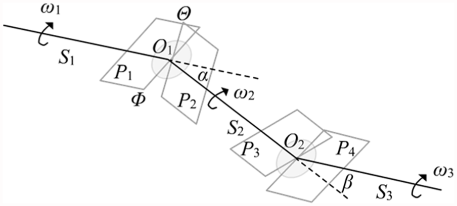
The movement mechanism of the transmission shaft of the double cross universal joint.
The configuration in which plane P1 is vertical to plane S1O1S2 (ΦO1⊥S1O1S2) is defined as the initial configuration of the transmission shaft, where
From the view of the projection plane that is vertical to the plane of the intermediate shaft S2 at O1, the trajectory of the intermediate shaft fork Θ is a circle, and the trajectory of the input shaft fork, Φ, is an ellipse (Figure 2). The following equations can be obtained, where increases in the input shaft angle and the intermediate shaft angle are


The relation between the input shaft and the intermediate shaft.
Equations (1)–(3) yields

In the motion system, the initial rotation angle is

The rotation angle of the fork of the intermediate angle is

For the transmission system,

From equation (7), we can obtain

The relation of the angular velocity between the intermediate and input shafts can now be derived 3

Therefore, the relation of the angular velocity between the output and input shafts can be obtained

The fault model of the double cross universal joint
The main faults of the universal transmission device are abnormal noise, vibration, and deformation; these are mainly caused by the faults such as looseness, wear, and intermediate shaft torsional deformation. When looseness and wear of the universal joint occur, the central axes in the universal joint will not be consistent, and a small distance

Sectional diagram of the universal shaft with faults.
In this article, we suppose that the fault is in the universal joint between the intermediate and output shafts. Therefore, for this faulty universal joint, the angle between the intermediate and output shafts,

In practical applications, if the joint clearance between the universal joint cross shaft journal and bearing is more than 0.25 mm, then abnormal noise and vibrations will be produced. This indicates that when Δd > 0.25 mm, the fault angle between the intermediate output shafts,
Model parameter analysis of the double cross universal joint
The constant relation between the angular velocities of the input and output transmission shafts is shown in equation (5). From this, we can find a set of model parameters that specify a constant input angular velocity that obtains a stable output angular velocity. We will therefore investigate the influence of the model parameters on the output angular velocities and obtain their optimal values. We set the constant angular velocity of the input shaft to be

Constant angular velocity of input shaft.
With a fixed
Model parameters of the double cross universal joints.

Parameter combination: α = 30; φ = 80, 110; β = 25, 30, 35, 40
Figure 5 shows that with fixed
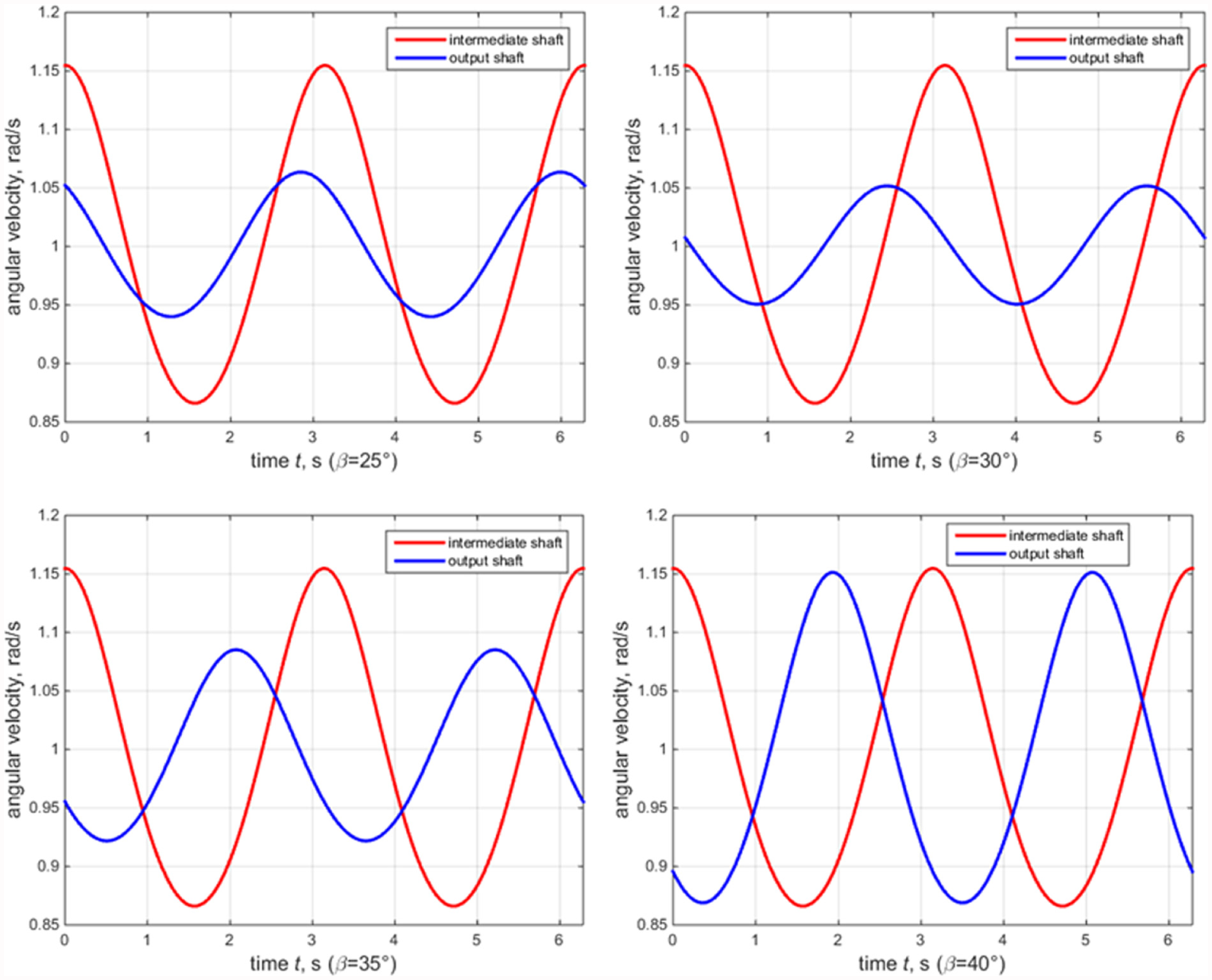
The angular velocities of the intermediate shaft

The angular velocities of the intermediate shaft
Parameter combination: α = 30; φ = 90; β = 25, 30, 35, 40
Figure 7 shows that with fixed

Angular velocities of the intermediate shaft
From the analysis above, we know that the smaller the difference between
Fault analysis of the double cross universal joint
When the universal joint is used for a long time, the fault will affect the delivery of the power, cause low transmission efficiency, increase fuel consumption and noise, and accelerate the wearing away of spare parts. Here, we analyze the influence of the three causes of universal joint failures on the output transmission, including looseness, wear, and torsional deformation.
If the universal joint exhibits looseness, the relationship between
Analysis of the looseness
Since after long-term use, the fit accuracy of the universal joint will no longer meet vehicle component assembly standard, some faults will emerge. The most common reason for a fault is looseness, for example, this looseness may appear in the moving angle of the universal joint, the fixed bolt of the connecting part, or the connecting bolt of the flange.
Based on the optimal transmission performance of
Figure 8 shows that with a fixed
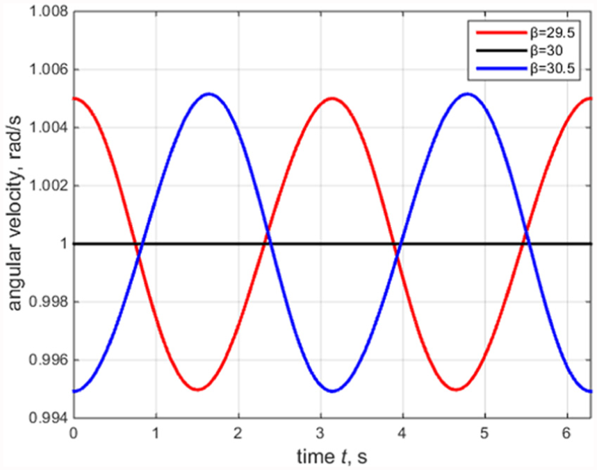
Angular velocity of the output shaft,
Figure 9 shows that when

Relationship between
For the analysis above, we know that when the universal joint is exhibiting looseness, the angular velocity of the output shaft has a large amplitude that affects the transmission performance. The performance of the angular velocity of the output shaft and the transmission become worse as the looseness increases. In this situation, noise and vibrations will occur more easily in the universal joint, which in turn will make the driving of the vehicle less safe.
Analysis of wear
Wear is a special type of looseness. Some parts of the universal joint will depress during high strength motion, and phenomena such as shaft wear, bearing wear, or even damage, may cause looseness. In this section, we study the wear of the universal joint and analyze the influence of the wear on the transmission performance.
The angle,

(a) β′/β versus time for four linear wear points and (b)–(d) the angular velocity of the output shaft,
Based on the optimal transmission performance
The variation in the angular velocity of the output shaft is obvious at the same wear points with looseness. For example, when
When
Therefore, the variation in the angular velocity of the output shaft is obvious in the scenario where wear occurs, and the transmission performance is duly affected. In addition, when the universal joint experiences both wear and looseness, the angular velocity of the output shaft becomes more unstable and the transmission performance also becomes worse; abnormal sounds, vibrations, and other faults are more likely to occur, which in turn reduce safety while driving a vehicle.
Figure 11 shows that with an increase in the variation of

Relationship between the angle variation,
Analysis of the intermediate shaft torsional deformation
The intermediate shaft is indispensable during the delivery of power in the universal transmission system. The main fault in the intermediate shaft that we will discuss is due to the torsional deformation that causes abnormal sounds and vibrations to occur. In this section, we describe the torsional deformation by varying the phase angle,
Based on the optimal transmission performance of
Figure 12 shows that the angular velocity of the output shaft is constant without any variation when the phase angle,

Relationship between the phase angle,
Figure 13(a) shows that in comparison to the phase angle
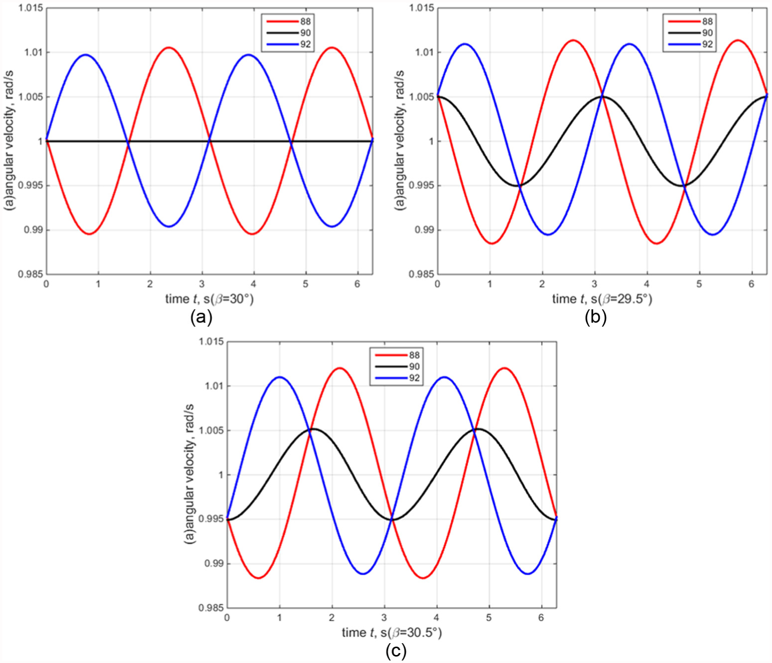
Angular velocity of the output shaft,
Figure 13(b) and (c) show that in the scenario for looseness, the angular velocity curves of the output shaft are unstable with all values of the phase angle. Meanwhile, when
Therefore, when the intermediate shaft has torsional deformation, which means that
Conclusion
In this article, we have studied faults that occur in the double cross universal joint, including looseness, wear, and intermediate shaft torsional deformation. A transmission model and a fault model of the double cross universal joint were built. An analysis of the parameters of the transmission model shows that when the angle of the two universal joints (α and β) are consistent, the phase angle, φ, equals 90; the angular velocity of the output shaft is therefore constant, which indicates optimal transmission performance.
Another contribution of this article is in the discussion on the transmission performance when affected by looseness, wear, and intermediate shaft torsional deformation. Our results show that when the universal joint is exhibiting looseness, the performance of the angular velocity of the output shaft and the transmission become worse as the looseness increases. For wear and intermediate shaft torsional deformation, the output angular velocity is also unstable. If looseness occurs at the same time as one of these two faults, the instability will be superimposed and the transmission performance will become even worse.
This article can help us to understand the faults of the universal joint. However, the drivetrain dynamics is also important for the faults analysis of the universal joint. This is the motivation that we will continue this research and try to study the mechanism of the transmission and the reasons of faults. We also will look to test the faults of real universal joints using the results of this study in order to generate guidance that is more applicable to real-world scenarios.
Footnotes
Academic Editor: Hamid Reza Shaker
Declaration of conflicting interests
The author(s) declared no potential conflicts of interest with respect to the research, authorship, and/or publication of this article.
Funding
The author(s) disclosed receipt of the following financial support for the research, authorship, and/or publication of this article: This work was supported by the National Natural Science Foundation of China (grant no. 61673300), the Natural Science Foundation of Shanghai (16ZR1424600), the University Young Teachers Training Program of Shanghai (ZZssd15054), and the University’s Scientific Research Project (grant no. SK201511).