
Abstract
A thermal energy storage system using U-tube heat exchanger is proposed and compared with the system using single-tube heat exchanger. Based on the enthalpy-porosity method, three-dimensional numerical models using computational fluid dynamics approach are developed to simulate the dynamic melting of phase change material in the two systems. Variable specific heat technique and combined conduction–convection heat transfer models are applied to achieve precise simulation. The model is first validated using published data, and then, the heat flux across the tube is used to evaluate the heat transfer performance of the two systems. Moreover, parametric studies are performed to analyze the effect of heat transfer fluid flow rate on the U-tube system by six different cases. The results show that during the melting of phase change material, vertical temperature stratification occurs in both systems as a result of the intensified natural convection. The results also demonstrate that the U-tube system has better heat transfer performance than the single-tube system which has the same heat transfer area and boundary conditions, reducing the total charging time by 25%. Increasing the heat transfer fluid flow rate greatly enhances the heat transfer performance for the U-tube system, but further enhancement is limited by the fixed heat transfer area. This study provides an effective method to investigate the thermal behavior of thermal energy storage using phase change materials, and the results can be helpful in optimizing the future thermal energy storage design and practical applications.
Keywords
Introduction
Over the last decade, the rapid economic growth with industrialization around the world has dramatically increased the demand of energy, and the overuse of fossil fuels has consequently caused a lot of associated environmental problems.1,2 To solve the imminent energy shortage and environmental crises, solar energy harvesting has been encouraged by many countries due to the advantages of being sustainable and not contributing to the world’s greenhouse gas emissions. 3 However, solar energy is unstable with different times, weathers, and seasons, which can limit the application of solar thermal system in some specific regions. 4 To ensure system reliability, the integration of proper thermal energy storage (TES) is considered as an important issue for the solar thermal system.
The basic TES techniques can be described as two types: sensible heat thermal energy storage (SHTES) system and latent heat thermal energy storage (LHTES) system. 5 Compared with the SHTES system, the main advantages of the LHTES system is the ability to provide higher energy storage density at relatively constant transition temperature using phase change materials (PCMs).6–9 Among various LHTES systems, shell-and-tube system has gained significant research attention due to its simple configuration and low cost. The shell-and-tube system usually consists of a well-insulated shell and a concentric tube. The PCM occupies the space between the tube and the shell, and the heat is transferred from heat transfer fluid (HTF) which is circulated through the tube. 10
The main objectives of the researches on the shell-and-tube system are to provide the guidelines for system optimization,11–14 improve the total TES performance,15,16 and analyze the parametric effects on the system.17–20
Trp 11 numerically investigated the transient forced convective heat transfer between the tube wall and the HTF with moderate Prandtl numbers. Results showed that the heat transfer from the HTF to the PCM was limited by the Prandtl number. Gasia et al. 12 evaluated the effect of dynamic melting technique in a cylindrical system using water as PCM. The dominance of forced convection was found to increase the overall heat transfer coefficient during the melting of PCM. Murray and Groulx13,14 experimentally studied the phase change process of dodecanoic acid under various charging and discharging conditions. They concluded that the natural convection was significant during the charging process, while it was negligible during the discharging process.
Tao et al. 15 numerically investigated the effects of three enhanced tubes on the TES performance of a high-temperature molten salt TES unit, including dimpled tube, cone-finned tube, and helically finned tube. It was found that the melting time can be reduced by 19.9%, 26.9%, and 30.7% for the three tubes, respectively. Liu et al. 16 numerically investigated the heat transfer enhancement technique using metal foam in a shell-and-tube system. In their model, appropriate source terms were added to the momentum equations to model the pressure drop caused by the presence of solid PCM and porous media.
Li et al. 17 numerically analyzed the effects of HTF inlet temperature and tube length on their system using three high-temperature PCMs. Results showed that the optimum inlet temperature and total length are 1200 K and 1200 mm, respectively. Seddegh et al. 18 numerically investigated the thermal behavior in a system with horizontal and vertical arrangement. They concluded that the horizontal arrangement had superior thermal performance during the charging. Similarly, Kousha et al. 19 experimentally studied the performance of a system subjected to various inclination angles. It was found that the angle variation affected the melting process more than the solidification process as a result of the dominance of convective heat transfer. Bechiri and Mansouri 20 developed an analytical model to predict the effects of volumetric heat generation on their system. In their model, the exponential integral function and variables separation method were used to achieve precise results.
The foregoing review indicates that numerical simulation using computational fluid dynamics (CFD) approach is effective in dealing with complex factors which greatly affect the PCM melting behavior. In this article, dynamic melting in two shell-and-tube PCM systems is numerically analyzed, including a single-tube system and a U-tube system. The main objective is to compare the heat transfer performance between the two systems which have the same heat transfer area and boundary conditions. The reliability of the numerical model is verified using published experimental data. 21 Then, the heat flux across the tube is used to evaluate the heat transfer performance of the two systems. Moreover, the influence of HTF flow rate on the U-tube system is examined by six different cases, which are considered as laminar flow and turbulent flow, respectively.
Model description
The schematic diagram of the single-tube system studied by Longeon et al. 21 is shown in Figure 1. The inner diameter of the single tube is 15 mm, the diameter of the shell is 40 mm, and the height of the system is 400 mm. The tube is made of stainless steel with a thickness of 2.5 mm. In order to enhance the heat transfer performance without changing the heat transfer area, a U-tube system is proposed, as shown in Figure 2(a). The inner diameter of the U-tube is 7.5 mm and the thickness is 1.25 mm. It can be seen that the vertical dimension of the system is much bigger than the horizontal one. In order to simplify the numerical model, a user-defined function (UDF) program is integrated to act as a temperature connection, as shown in Figure 2(b). The U-tube length (800 mm) is twice as long as the single-tube length (400 mm), and therefore, the total heat transfer area is the same in both systems. Moreover, due to a smaller total tube volume, the U-tube system can store more PCMs and thermal energy than the single-tube system.

Schematic diagram of the single-tube system studied by Longeon et al. 21
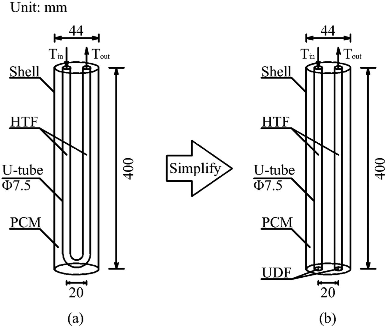
Schematic diagram of the U-tube system: (a) physical model and (b) numerical model with simplification.
In the study by Longeon et al., 21 paraffin RT35 and water were used as the PCM and HTF, respectively. The physical and thermal properties are given in Table 1. According to the previous studies of the thermal behavior of pure paraffin,21–23 the specific heat of paraffin can be approximately considered as a function of temperature. Therefore, the total heat of fusion can be calculated through the variable specific heat; this technique enables solving the phase change problem precisely. As shown in Figure 3, 21 the total heat of fusion (including sensible heat and latent heat) is 250 kJ/kg, and the solidus and liquidus are deemed to be 28°C and 38°C, respectively. In this study, both systems are vertically arranged to induce convective motion in the liquid PCM, which is caused by buoyancy effects. 24
Physical and thermal properties of the PCM and HTF. 21

PCM: phase change material; HTF: heat transfer fluid.
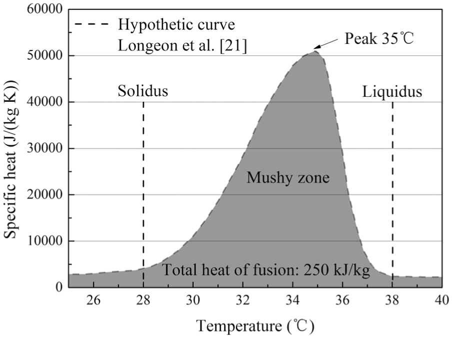
Specific heat measurement of the PCM by Longeon et al. 21
Numerical method
During the melting of PCM, the coexistence of heat conduction, natural convection, and phase change will lead to a coupled heat transfer problem. In order to simplify the numerical simulation, the following assumptions are considered:
The heat loss during the charging is negligible.
The HTF is incompressible and considered as the Newtonian fluid.
Both solid and liquid PCMs are homogeneous and isotropic.
The PCM motion in the liquid phase is laminar, unsteady, and incompressible.
The viscous dissipation is negligible.
The natural convection in the liquid PCM is taken into account using the Boussinesq approximation, which treats the PCM density as a variable value only in a source term of the momentum equation

where
Governing equation
To solve the coupled heat transfer problem, the enthalpy-porosity method is applied.15–19 In this method, the governing equation is the same for both solid and liquid phases, and the solid–liquid interface is indicated by a mushy zone instead of being explicitly tracked. 18 The governing equations for the PCM are given as follows:
Continuity

Momentum

Energy

where

The sensible enthalpy

where
And, the latent enthalpy

where

It should be noticed that
The source term

where
Boundary and initial conditions
In both systems, the boundary conditions on the outer surface of the shell are adiabatic, the PCM initial temperature is 22°C, and the HTF inlet temperature is 52°C. In the charging mode investigated by Longeon et al., the HTF inlet velocity was 0.01 m/s. In order to keep an equal flow rate, 0.04 m/s is used in the U-tube system since the single-tube diameter is twice as long as the U-tube diameter.
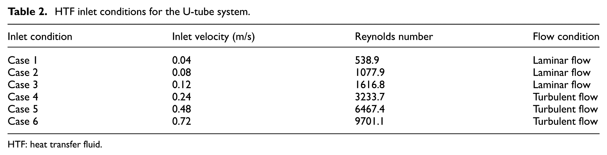
In order to examine the effect of HTF flow rate on the heat transfer performance of the U-tube system, three laminar flow cases and three turbulent flow cases are applied based on the Reynolds number, as given in Table 2.
HTF inlet conditions for the U-tube system.
HTF: heat transfer fluid.
Numerical procedure
The creation of geometry and three-dimensional (3D) mesh for the two models is conducted using the preprocessor Gambit 2.4.6. The coupled heat transfer process is modeled using the commercial CFD code Fluent 15.0. The laminar model and the standard k–ε model are used for solving the specified flow of HTF, and the solidification and melting model is used for solving the melting of PCM. The Semi-Implicit Method for Pressure Linked Equations (SIMPLE) algorithm is used to discretize the pressure–velocity coupling, the PRESTO scheme is used to discretize the pressure correction, and the second-order upwind scheme is used to discretize the governing equations. The influence of time step and grid size was carefully examined in the preliminary calculation. Considering the calculation time and accuracy, 0.2 s is adopted as the time step for both models; 31,620 and 32,960 grids are adopted as the grid size for the single-tube model and the U-tube model, respectively. Convergence of the solution is checked for each time step with criterion of 10−7 for the energy equation and 10−3 for other variables.
Results and discussion
Numerical model validation
In Figure 4, the comparison of the measured temperature in “D section c point” of the Longeon et al. experiment and the present numerical result of the single-tube model is shown. A good agreement can be seen from the comparison, which verifies the reliability of the numerical model for solving the phase change problem. The PCM temperature undergoes a stable increase from 0 to 1000 s, which can be explained by the dominance of heat conduction in the solid phase. Then, the PCM shows a smooth temperature growth during the period between 1000 and 3000 s. During this interval, the PCM is melting and absorbing the latent heat due to its increasing specific heat. However, a sudden surge in temperature occurs after 3000 s, which is induced by the convective flow in the liquid phase. In conclusion, the application of variable specific heat technique and combined conduction–convection heat transfer models are important to achieve precise simulation.
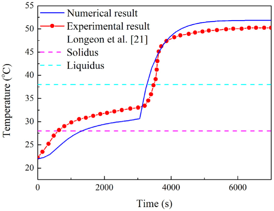
Comparison of the measured temperature in “D section c point” of the Longeon et al. 21 experiment and the present numerical result of the single-tube model.
Comparison between the two systems
The contours of temperature distribution and liquid fraction for the single-tube system are shown in Figure 5(a) and (b), respectively. In Figure 5(a), the outer surface of the system shows vertical temperature stratification during the charging. This can be attributed to the combined conduction–convection heat transfer mechanism analyzed above. At the charging beginning, the heat transferred across the tube wall rises the PCM temperature through heat conduction. In Figure 5(b), when the PCM melts, a thin layer of liquid PCM is formed between the tube and the shell. Meanwhile, due to the thermal gradient and the buoyancy effect, the low-density PCM at high temperature moves upward, and the high-density PCM at low temperature moves downward, inducing the convective heat transfer. As natural convection intensifies, the melted PCM region expands in vertical direction with symmetric distribution. These findings are consistent with the results reported in previous literatures.10,21,24

Temperature distribution and liquid fraction for the single-tube system: (a) outer surface temperature distribution and (b) liquid fraction in vertical section.
Figure 6(a) shows the outer surface temperature distribution contour for the U-tube system, and the vertical temperature stratification is also formed. However, the liquid fraction contour shown in Figure 6(b) is quite different compared with Figure 5(b). The main differences are as follows. (1) The melted PCM region is not symmetrically distributed. This is due to the temperature difference between the tubes: the inlet tube has higher average temperature than the outlet one, inducing bigger thermal gradient in radial direction. (2) The PCM undergoes a faster phase transition in the U-tube system, which indicates that the heat transfer performance of the U-tube is better than that of the single tube under the same boundary conditions. This is mainly because the U-tube volume is smaller than the single-tube volume, and therefore, it makes slighter impediment to the convective motion in liquid PCM. In conclusion, the U-tube is more helpful in inducing a stronger natural convection effect than the single tube.
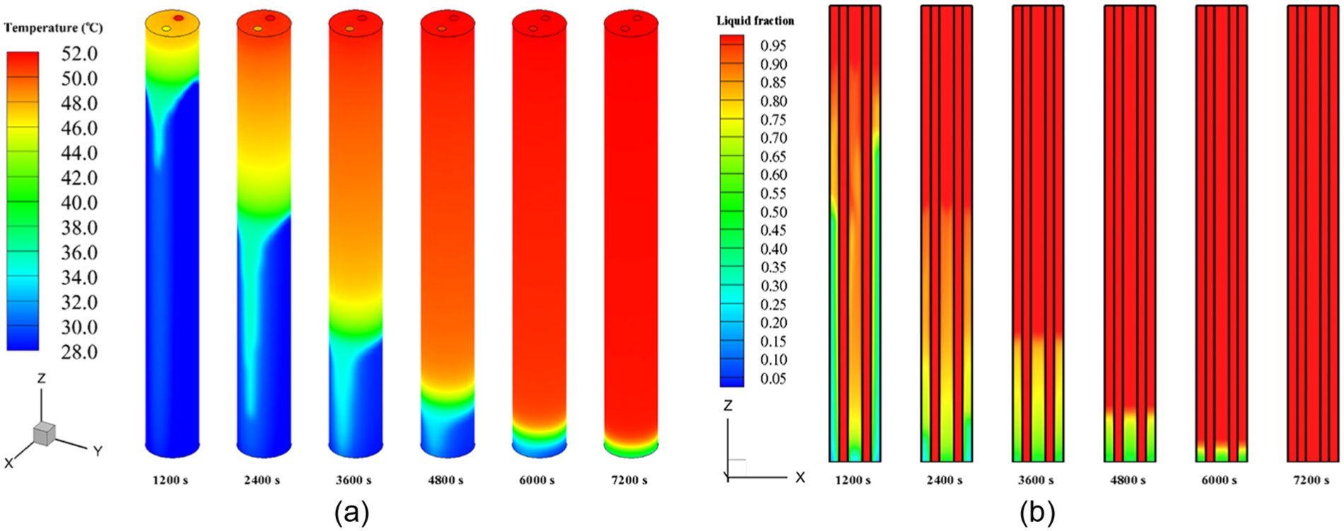
Temperature distribution and liquid fraction for the U-tube system: (a) outer surface temperature distribution and (b) liquid fraction in vertical section.
To evaluate the heat transfer performance of the two systems, the heat flux across the tube is adopted, as shown in Figure 7. It can be seen that the U-tube system has a larger integral area than the single-tube system, which indicates that the average charging power for the U-tube system is bigger. Moreover, the heat flux decreases sharply for both systems at the beginning of the charging. This is mainly because the PCM conductivity is low, and meanwhile, the heat conduction plays a leading role during this period. However, a fluctuation alleviates the sharp decrease as circled in Figure 7. This can be explained by the transition of the heat transfer mechanism, changing from the heat conduction to the natural convection. Figure 8 shows the average temperature and liquid fraction of PCM for the two systems. It can be seen that the charging time is around 8000 s for the single-tube system, and this figure is reduced by 25% for the U-tube system with around 6000 s.

Heat flux across the tube for the two systems.

Average temperature and liquid fraction of PCM for the two systems: (a) average temperature profile and (b) liquid fraction profile.
Effect of HTF flow rate
The effect of HTF flow rate on the charging process has been investigated in a lot of previous literatures; some authors mentioned that the HTF flow rate significantly influenced the charging process,14,25 but some authors also claimed that increasing the HTF flow rate did not greatly affect the charging process. 26 Therefore, it is necessary to conduct a detailed parametric study on the HTF flow rate for the U-tube system. The heat flux, average temperature, and liquid fraction of PCM under different HTF flow rates are shown in Figures 9 and 10. It can be seen from these figures that the cases in turbulent flow (cases 4–6) have better heat transfer performance than the cases in laminar flow (cases 1–3). This can be attributed to the forced convection enhancement when the HTF flow rate and the Reynolds number increase. However, because the heat transfer area of the U-tube is fixed, the heat flux across the tube wall will be limited by the area even though the forced convection keeps enhancing. Therefore, the further enhancement by increasing the HTF flow rate (cases 4–6) shows almost no apparent effect.
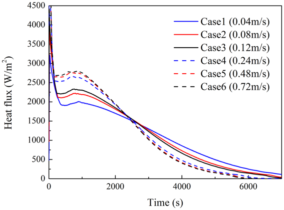
Heat flux across the tube for the U-tube system under different HTF flow rates.

Average temperature and liquid fraction of PCM for the U-tube system under different HTF flow rates: (a) average temperature profile and (b) liquid fraction profile.
Conclusion
In this article, a U-tube TES system is proposed and compared with the single-tube system using numerical approach. Paraffin RT35 and water are used as the PCM and HTF, respectively. A UDF program is integrated to simplify the numerical model, and variable specific heat technique is adopted to achieve precise simulation. The numerical model can accurately describe the melting behavior when a combined conduction–convection heat transfer mechanism is adopted. The results demonstrate that the U-tube system has better heat transfer performance than the single-tube system which has the same heat transfer area and boundary conditions, reducing the total charging time by 25%. The parametric study indicates that the HTF in turbulent flow contributes to a better heat transfer performance, but the further enhancement through increasing the HTF flow rate is limited by the fixed heat transfer area. The numerical method in this study can be extended to investigate different PCMs and optimize the future TES design.
Footnotes
Nomenclatures
Amush Mushy zone constant (kg/(m3 s))
Cp Specific heat (kJ/(kg K))
g Gravity (m/s2)
H Total enthalpy (kJ/kg)
h Sensible enthalpy (kJ/kg)
h ref Reference enthalpy (kJ/kg)
ΔH Latent enthalpy (kJ/kg)
k Thermal conductivity (W/(m2 K)).
L Latent heat (kJ/kg)
P Pressure (Pa)
T Temperature (°C)
T ref Reference temperature (°C)
T s Solidus temperature (°C)
T l Liquidus temperature (°C)
t Time (s)
S Source term
u Velocity (m/s)
Academic Editor: Shuli Liu
Declaration of conflicting interests
The author(s) declared no potential conflicts of interest with respect to the research, authorship, and/or publication of this article.
Funding
The author(s) disclosed receipt of the following financial support for the research, authorship, and/or publication of this article: This research is financially supported by the Science and Technology Ministry of China (no. 2016YFC0700406), the Chongqing Technology and Welfare Plan (no. cstc2015jcsf 90003–4), and the 111 Project (no. B13041).