
Abstract
In this article, the specimen of Q235 (low carbon steel, C ≤ 0.22%, Mn: 0.3%–0.8%, Si ≤ 0.3%, P ≤ 0.045%, S ≤ 0.05%) has been tested in in situ tensile tests. Especially, different types of scratches are prefabricated with 1, 2, and 3 µm in depth. In addition, three scratch angles (θ = 0°, 45°, and 90°) are adopted to explore the changes of tensile strength. The cross profile of the scratch groove is measured with in situ observation method (Olympus DSX500), which is taken as an important indicator to verify the experiments. According to the results of experiments, scratch depth and angle can influence the tensile strength of material. When the depth and scratch angle increase, there is a decrement in the value of tensile strength. This indicates that the surface damage really has effect on the tensile strength of specimen.
Introduction
Scratch method is widely utilized in scientific works to obtain the mechanical properties, deformation behavior, fracture data of material, and the ability of surface material to resist the scratch damage. The scratch process is that the indenter penetrates into the specimen and move the indenter along the specimen surface. For example, on the basis of the transverse forces and vertical force obtained via load sensor during the test, the mechanical property such as friction factor can be calculated at last. Oxide film1–3 has been tested in order to verify the performance reinforcement using scratch method under different environments. Different alloy films are targeted by scientists. They have studied the tribological and mechanical properties of TiVN, Cr2N-11Ag, Ti-6Al-4V, Cr-Ti-B-N, Ti/TiB2, and Mo-Ru4–9 films with factors changing. Besides the material of films, films with different structures have been tested like nano-multilayer coatings. 10 In addition, nanometer-thick coatings 11 and ultra nanocrystalline diamond films 12 have been tested as well. In recent years, in situ observing means have been utilized in material testing field especially in scratch tests. 13 In situ observation means that the real-time surface morphology of specimen during test can be obtained utilizing imaging device such as microscope. In scratch test, the optical in situ test has several benefits, such as the compatibility to environment of test, the material images with different colors and various different imaging modes. 14 The optical microscope is fixed beside the indenter; the lens of the microscope focuses on the area between indenter and specimen. The real-time images can be obtained during the scratch test. Surface morphology of specimen can also be observed such as how the cuttings flow to both sides of indenter, which is the ex situ test, cannot achieve.
For engineering application, there are several factors affecting the mechanical properties of specimen. Adulterant such as submicron and nano SiC particles 15 and hard/soft fillers 16 has large influence on the wear and scratch behavior. Additionally, surface damage, which includes fracture and wear, can change the mechanical abilities of specimen. For example, contact damage of fretting wear can alter the failure performance 17 and the stick-slip phenomenon of polypropylene can alter the scratch performance. 18 The importance of sample preparation is also discussed through the surface failure and wear tests of cemented carbide rock drill buttons. 19 And the ability of fatigue with material defects has been studied. 20 Beneficial effects of yttrium have been gained through surface aluminized technology. 21 All these above show the significant effects on material mechanical properties with surface damage.
However, the works above did not pay attention to the change of mechanical property due to the scratch. Scratch can also be considered as a type of surface damage. The depth and angle of scratch can affect the mechanical properties directly in tensile tests. Therefore, the purpose of this article is to experimentally investigate the changes of tensile strength in tensile test attributing to the scratch depth and angle with the in situ testing method and fracture mechanics theory. The experimental details and results are presented and discussed, respectively. Finally, the concluding remarks have been drawn.
Experiment procedure
Specimen and preparation
The specimen is shown in Figure 1(a). The scratches are in the gauge area, which are fabricated using scratch tester. The gauge area is zoomed shown in Figure 1(b). Scratches with different depths and angles are fabricated on the specimen before tensile test. The scratch lengths of three directions are all 1 mm. Three kinds of depths are adopted which include 1, 2, and 3 µm. All surface morphologies of the specimens before tensile test are shown in Table 1. The scratch cross profiles, which includes width and depth of scratch, are shown in Figure 2.
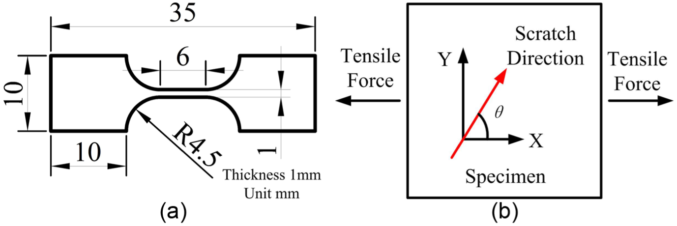
(a) The dimensions of specimen and (b) the schematic diagram of scratch angle (zoomed gauge area).
Surface morphologies of three directions with 1, 2, and 3 µm depths before tests.


Cross profiles of the scratches with three kinds of depths.
Tensile test
The tensile tester is shown in Figure 3(a). The specimen has been symmetrically clamped on the fixtures. Tensile force is applied to the specimen along the X-axis. The middle line of the specimen and that of tensile force are coaxial. During the test, quasi-static test method is applied via controlling the tensile speed of 10 µm/s. Load and displacement sensors are utilized to obtain the experimental data. At the same time, in situ observation is accomplished using the microscope. Finally, the stress–strain curves and the observation images are recorded.
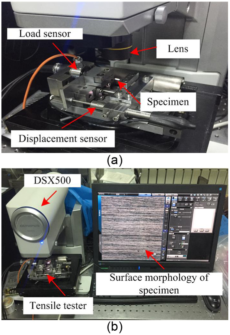
(a) The diagram of tensile tester and (b) the diagram of in situ observation.
In situ measurement method
The most advisable advantage for in situ tests is the real-time measurement of the surface morphology during the tests. Optical microscope is widely utilized to observe the specimen surface. Olympus DSX500 is adopted to accomplish the cross profile measurement of scratch, which is shown in Figure 3(b). The tensile tester is put under the lens of microscope. The lens is right there above the specimen gauge area. Surface morphology of gauge area is shown on the screen at the same time. With the specimen deforming during tensile test, the change of surface morphology is clearly presented. According to this, the real-time measurement of the surface morphology can be achieved.
It is worth mentioning that the cross profile of scratch groove is an important evaluating indicator of surface morphology. The deformation of the scratch can directly express the deformation state of specimen. The scratch varies in both along the tensile axis and also the axis perpendicular to the surface during tensile test. Due to the high depth of field, the microscope realizes the cross-profile measurement. The microscope can measure the variation of scratch in axis perpendicular to the surface via serial layer scanning process. Finally, the surface morphology is shown on the screen. In order to guarantee the accuracy of the data, averaging the measurement of three times is applied.
Results and discussions
Surface morphologies, stress–strain curves, and the cross profiles of the scratches after the tensile tests are shown in Table 2, Figures 4 and 5. It is mentionable that the stress in stress–strain curve is nominal stress. With the purpose of analyzing the experiments well, the surface morphologies and cross profiles are measured when the tensile stress is 300 MPa, and the results show that the scratches behave differently. Depth and angle of the scratches are discussed as main factors affecting the tensile strength of specimen.
Surface morphologies of three directions with 1, 2, and 3 µm depths after tensile tests.


Stress-strain curves of the three kinds of scratches: (a) 1 µm depth scratch, (b) 2 µm depth scratch, and (c) 3 µm depth scratch.

Cross profiles of the three kinds of scratches: (a) 1 µm depth scratch, (b) 2 µm depth scratch, and (c) 3 µm depth scratch.
Influence of scratch depth
Scratch can be considered as a man-made surface damage on the specimen. Varied scratch depths provide different sectional dimensions, which change the material performance remarkably. According to the data of the tensile tests, the tensile strength changes correspondingly with the scratch depth varying. The tensile strength with no scratch is 397.3 MPa. When θ = 0°, the tensile strengths are 393.1, 377.8, and 357 MPa matching with the scratch depths of 1, 2, and 3 µm. When θ = 45°, the values are 388.1, 369.3, and 343 MPa. When θ = 90°, the values are 380.8, 360.4, and 335 MPa.
As shown in Figure 2, the depth and width of 3 µm deep scratch are 3.048 and 30.891 µm, which are larger than those of 1 and 2 µm scratches. With the depth of the scratch increasing, the cross-sectional area of scratch decreases. For the same tensile force, according to the material mechanics, when the sectional area decreases, the partial stress increases. Therefore, the scratch is deeper, the stress of scratch area is larger, and the stress concentration is more obvious.
Here takes the θ = 0° direction as an example. Comparing with Figures 2 and 5, the increased depths of the scratches for 1, 2, and 3 µm are 0.099, 1.521, and 2.506 µm. The increased widths of the scratches are 5.001, 17.072, and 24.238 µm. It can be seen that the cross-profile deformation of deeper scratch is bigger than the others. This indicates that when the stress concentration is more obvious, the tensile strength decreases. When θ = 0°, the decreases of tensile strengths are 4.2, 19.5, and 40.3 MPa matching with the scratch depths of 1, 2, and 3 µm. When θ = 90°, the decreases are 16.5, 36.9, and 63.3 MPa. When θ = 45°, the decreases are 12.2, 28, and 54.3 MPa. These results have proven that the scratch depth can influence the tensile strength. When the scratch depth increases, the tensile strength of specimen decreases.
Influence of scratch angle
The scratch angle changes the stress state of the scratch as shown in Figure 6.

(a) The theory schematic diagram and (b) the stress state schematic diagram.
The shear stress appears because of the scratch angle. The shear stress varies with the scratch angle changing, which influences the tensile strength of specimen. In material mechanics, σ = σ0 sin 2θ and τ = σ0 sin θ cos θ


where

According to the fracture mechanics, the critical stress is the main evaluation indicator for crack propagation. When the stress reaches the critical stress, the scratch begins to propagate. The ability to resist deformation decreases. Therefore, the less the critical stress, the less the tensile strength. The critical stress for θ = 0°, 45°, and 90° are shown in Table 3. When θ = 0°, the critical stress reaches the limit, the value is infinitely great. The critical stress decreases with the θ increasing. Finally, the tensile strength decreases.
Critical stress for three scratches angle.

In this section, in order to analyze the effects of different scratch angles, comparison of the experiments with the same scratch depth is drawn. Therefore, scratch angle is the main discussed point. For 1 µm deep scratches, the tensile strengths are 393.1, 388.1, and 380.8 MPa matching with θ = 0°, 45°, and 90° directions. The values of 2 µm deep scratches are 377.8, 369.3, and 360.4 MPa. The values of 3 µm deep scratches are 357, 343, and 335 MPa.
The deformation of scratch mainly reflects in the cross profile of scratch groove. Here, take the 1 µm deep scratch as an example. In Figure 5, the increased depths of the scratches for θ = 0°, 45°, and 90° are 0.099, 0.608, and 1.913 µm. The increased widths of the grooves are 5.001, 7.534, and 24.237 µm. Therefore, the cross-profile deformation with larger scratch angle is bigger than the others. This is because the critical stress in 90° direction is less than the other two, which is shown in Table 3. The scratch begins to propagate under lower tensile load. Finally, the tensile strength decreases in tensile tests.
For 1 µm deep scratch, the decreases of tensile strengths are 4.2, 9.2, and 16.5 MPa matching with θ = 0°, 45°, and 90°. The values for 2 µm deep scratches are 19.5, 28, and 36.9 MPa. The values for 3 µm deep scratches are 40.3, 54.3, and 62.3 MPa. The decrease of tensile strength is relative to the change of the stress state due to the scratch angle. These experimental results have proven that the tensile strength varying as the theory of fracture mechanics above.
Conclusion
To sum up, for the material like Q235 (low carbon steel), the depth and angle of scratch play important roles in influencing the tensile strength. All tests corroborate each other to indicate the effects of scratch depth and angle in tensile test. It could be concluded that
Tensile strength is influenced by the scratch depth. Bigger scratch depth brings more obvious stress concentration. Finally, the tensile strength decreases. Therefore, when scratch depth increases, the tensile strength of specimen decreases.
Due to the fracture mechanics theory, tensile strength of specimen is influenced by the scratch angle. When the scratch angle θ increases, the critical stress decreases. Therefore, the tensile strength decreases because the scratch begins to propagate under lower tensile load.
On the basis of the theories and experimental results, the factors of scratch which include depth and angle actually influence the tensile strength of specimen. Discrepant mechanical properties in tensile tests have been obtained due to the different factors. For engineering application, tensile strength of material is a very important indicator. According to the result in this article, when the surface damage like scratch exists on the material surface in engineering application, the mechanical behavior of material can be predicted before failure or fracture happens. According to this, the economic loss in engineering can be reduced.
Footnotes
Academic Editor: Filippo Berto
Declaration of conflicting interests
The author(s) declared no potential conflicts of interest with respect to the research, authorship, and/or publication of this article.
Funding
The author(s) disclosed receipt of the following financial support for the research, authorship, and/or publication of this article: This research is funded by the National Natural Science Foundation of China (grant no. 51275198), the National Natural Science Funds for Excellent Young Scholar (grant no. 51422503), Jilin province science and technology development plan major science and technology research projects (grant no. 20150203014GX), Jilin provincial economic structure strategic adjustment lead special projects (grant no. 2014Z045), Graduate Innovation Fund of Jilin University (project no. 2016073), and Special Projects for Development of National Major Scientific Instruments and Equipments (grant no. 2012YQ030075).