
Abstract
The level of detail required for a three-dimensional computer-aided design model varies according to its purpose. Thus, it is necessary to develop an automated method for controlling the level of detail of three-dimensional computer-aided design models to facilitate the use of three-dimensional computer-aided design models in different application areas. When multiple three-dimensional computer-aided design models need to be simplified in a batch mode without user intervention, it would be advantageous if the appropriate level of details for the models were automatically determined. This study proposes a new and automated method to determine the appropriate level of detail of each three-dimensional computer-aided design model during the simplification phase. To achieve this goal, the concept of an “appropriate level of detail for simplification” was defined from the viewpoint of shape dissimilarity. After that, an algorithm was developed to determine the appropriate level of detail of a model by adopting the feature-based simplification method and the shape distribution–based comparison method. Finally, a prototype system was invented to verify the proposed method through experiments, in which the appropriate level of details for test cases were determined by the system.
Keywords
Introduction
The application areas of three-dimensional (3D) computer-aided design (CAD) models have significantly expanded, and the level of detail (LOD) required for a 3D CAD model differs according to its purpose. At present, the LOD of a 3D CAD model is manually controlled by a user. This process is expensive and time-consuming. Furthermore, the process is prone to result in a 3D CAD model with an inappropriate LOD. Therefore, it is important to simplify a 3D CAD model in order to meet the required LOD of the 3D CAD for its purpose. 1 Due to this reason, many studies1–10 have been conducted for the simplification of 3D CAD models in various fields.
The main techniques for the simplification of a 3D CAD model are evaluation metrics and simplification operations. 1 Evaluation metrics are used to calculate the quantitative importance of each element in a 3D CAD model in order to determine whether an element should be maintained or removed based on its importance. Simplification operations are used to remove the selected element and fill up the void caused by the removal. Different simplification operations, including edge collapse, 2 volume-split 6 and wrap-around 7 operations, and feature rearrangement and removal, 9 are applied depending on the type of 3D model.
When 3D CAD models are simplified, they need to meet the following requirements: first, shape similarity between the original and a simplified model should be maintained at a high level, as per user expectation. Second, the data size of a simplified model should be minimized, when compared to that of the original model. Generally, a lower LOD model has a lower data size since the modeling elements are removed during simplification. Consequently, it is difficult to meet two requirements mentioned above, simultaneously. Therefore, it is important to determine an appropriate LOD for a 3D CAD model from the viewpoint of shape similarity. Each 3D CAD model has its own appropriate LOD, which is different from other 3D CAD models.
In older studies, users were expected to determine desired LOD during the simplification of a 3D CAD model. However, there are cases in which the appropriate LOD for each 3D CAD model needs to be calculated automatically—that is, simplifying several 3D CAD models in a batch processing mode, simplifying a 3D CAD model without human interventions, and suggesting an appropriate LOD for a given 3D CAD model to the user. In addition, a required LOD is different depending on the input model. As shown in the experimental results of Kwon et al., 11 the appropriate LOD determined by the user for the pump model and the appropriate LOD for the frame model are different from each other. Therefore, if we want to simplify multiple models at batch mode or to complete the simplification automatically without user intervention, a method to find an appropriate LOD value for a given model is necessary because appropriate LODs vary depending on models.
At the detailed design stage in the process plant industry, for example, engineering, procurement, and construction (EPC) companies need simplified 3D models for equipment and materials comprising a process plant but equipment suppliers provide detailed 3D CAD models; it means model simplification is necessary. Moreover, the number of equipment and materials used for the construction of a process plant is tremendously large. In this circumstance, users have to manually simplify large 3D CAD models for equipment and materials because they need to determine an appropriate LOD for a specific model which varies depending on the model. This simplification process takes a lot of time and human resources. Thus, simplifying many 3D CAD models in a batch mode will be more efficient than simplifying 3D CAD models one-at-a-time, by a user. In the manufacturing industry, it is required to prepare 3D CAD models to build a virtual factory used at performing production simulations. In this case, it is also necessary to convert 3D CAD models with high LOD to models with low LOD for a large number of facilities comprising a factory.
Users consider several factors to determine the appropriate LOD for a 3D CAD model. One important factor is that the shape similarity between the original model and a simplified model should be maintained at a higher level while eliminating as many elements as possible. Kwon et al. 1 and Kang et al. 8 suggested methods to assign lower importance to features that have little effect on preserving the outer shape of a model, and to help them be eliminated in the early stage of simplification. Their studies can be understood in the same context as shape similarity.
This article proposes a new and automated method to determine the appropriate LOD of each 3D CAD model without human intervention during the simplification phase. In the proposed method, the permissible value of similarity is first set by the user. A set of simplified models is generated using the feature-based simplification method. 10 Shape similarity between the original model and each simplified model is evaluated quantitatively using the shape distribution-based method. 12 The LOD of simplified model, which has the closest shape similarity to the permissible value, is designated as the appropriate LOD.
The remainder of the article is organized as follows: Studies related to the simplification of 3D CAD models and comparison of 3D shapes will be reviewed in section “Review of related studies.” A method to determine the appropriate LOD for a 3D CAD model during the simplification phase is proposed in section “Determination of the appropriate LOD for a 3D CAD model.” In section “Experiments and verification,” experiments to determine appropriate LODs for test cases are performed and the experimental results are discussed. After this study’s conclusion is presented, section “Conclusion” discusses the project team’s future work.
Review of related studies
3D CAD model simplification
Existing methods for the simplification of 3D CAD model can be classified as follows: polygon-based,2–4 boundary-representation (B-rep)-based,5–7 and feature-based methods1,8–10 depending on the representation method of the 3D CAD model.
The polygon-based method is mainly used for flexible LOD control in the field of computer graphics. For instance, the LOD of a polygonal model is dependent on the user’s point of view, and it is determined by distance, pixel size, eccentricity, and relative velocity with respect to the user’s point of view. 13 To lower the LOD of a polygonal model, the number of triangles that comprise a mesh should be decreased. In general, a model with a dense and regular mesh is preferred for a better result, and adaptive ways of simplification have, of late, become popular for maintaining the outer shape of models. 4
The B-rep-based method focuses either on the removal of elements that share a specific topological pattern in 3D CAD models 5 or on the recognition and removal of recognized local features. 6 Dimension reduction, local feature suppression, and volume decomposition are the most typical methods. This method is widely utilized for pre-processing in finite element analysis (FEA).
In the feature-based method, the LOD of a 3D CAD model can be progressively controlled by calculating the importance of the totality of features, rearranging the order of features according to importance, and then suppressing features with low importance. The importance of each feature is evaluated using evaluation metrics, and evaluation metrics are defined depending on the purpose of the 3D CAD model. 1
There have been a number of studies that have proposed simplification algorithms or evaluation metrics. If we want to simplify multiple models at batch mode or to complete the simplification automatically without user intervention, a method to find an appropriate LOD value for a given model is necessary because appropriate LODs vary depending on models. However, to the best of our knowledge, there have been no studies suggesting a method for determining an appropriate LOD of a 3D CAD model using simplification and shape comparison technologies.
3D shape comparison
To compare two individual 3D shapes, it is required to generate shape descriptors for each shape, which contain characteristics of the shape. The shape similarity between two 3D shapes can then be evaluated by comparing the two shape descriptors. 14 The similarity comparison methods can be classified as follows, according to the user input data for generating a shape descriptor: global feature-based, manufacturing feature-based, graph-based, 3D object recognition-based, histogram-based, and product information-based. 15
Paquet et al. 16 proposed a simple method for representing the rough shape, size, and composition properties of an object for 3D shape matching. Ramesh et al. 17 suggested a similarity comparison method based on the manufacturing feature, in order to search mechanical parts. El-Mehalawi and Miller 18 developed a representation method to make a graph for the comparison of 3D CAD models of engineering parts. Horn 19 reported that extended Gaussian images were useful in representing a curved surface, which fit object recognition.
Hermann and Singh 20 proposed a plan-based design similarity measure to improve variant process planning by explicitly calculating the similarity of process planning. Rodríguez and Egenhofer 21 presented a semantic similarity evaluation method to calculate the semantic similarity of an element itself, or between an element and its neighbors. Alizon et al. 22 suggested a method for reusing manufacturing knowledge to measure the similarity between parts. To improve the accuracy of the method proposed in Alizon et al., 22 Mun and Ramani 23 used ontology and multi-criteria decision-making (MCDM) technique.
Osada et al. 24 presented a method that represents the signature of an object as a shape distribution for comparison of 3D mesh models. Ohbuchi et al. 12 enhanced the method proposed by Osada et al. by introducing the angle-distance and absolute angle-distance (AAD) histograms, which are calculated based on the D2 shape function. Tangelder and Veltkamp 25 used as shape descriptors weighted point sets that can be viewed as 3D probability distributions. Hwang et al. 26 presented shape-similarity measurements using ray distance-to-surface (RDS) and normalized ray distance-to-surface (NRDS).
Ip et al. 27 proposed a method to create four shape distributions according to each of the point-pair categories, namely the ALL, IN, OUT, and MIXED point pairs, and to use them as the shape descriptors of a 3D CAD model. Cheng et al. 28 developed a similarity evaluation method to integrate shape distribution and negative feature decomposition. Similarly, Chu and Hsu 29 adopted an integrated method to utilize multiple shape signatures: feature adjacency graphs, topological graphs, and shape distributions.
Existing shape comparison studies mainly focused on developing a method to measure the similarity of two different models more accurately. In particular, the main goal was to acquire the model most similar to a query model and reuse the acquired model for various purposes. In this study, shape comparison method is used as a tool for determining an appropriate LOD for a specific model during the simplification process.
Determination of the appropriate LOD for a 3D CAD model
Basic concept for determining the appropriate LOD
As the LOD goes down during simplification, data size as well as shape similarity between the original model and a simplified model is reduced. For the purpose of simplification, it is required to make a simplified model have as low an LOD as possible, to minimize data size. However, if dissimilarity between the original model and a simplified model exceeds the range acceptable to a user, the simplified model is not useful to the user. Therefore, an LOD should be found at which an original 3D CAD model is simplified as much as possible, and the guarantee of a certain level of shape similarity exists between the original 3D CAD model and the simplified one. Therefore, from the perspective of simplification, the appropriate LOD of a 3D CAD model can be defined as the minimum LOD of a simplified 3D CAD model in which shape dissimilarity between the original and the simplified 3D CAD models is within the allowable extent set by a user.
The proposed system framework for the determination of an appropriate LOD for a 3D CAD model is shown in Figure 1. The system consists of four main modules:
3D CAD Model Manager: this receives the original 3D CAD model from a user. It returns a simplified 3D CAD model with an appropriate LOD to a user.
3D CAD Model Simplifier: this gradually simplifies an original 3D CAD model and makes simplified 3D CAD models with different LODs.
Shape Similarity Manager: this generates shape descriptors for original and simplified 3D CAD models and stores them in the database. It also provides pre-processing functions used for making shape descriptors.
LOD Decision-Maker: this receives the permissible dissimilarity (e.g. 10% of dissimilarity) from a user. It also compares the shape descriptors of original and simplified 3D CAD models to calculate similarity, and determines appropriate LOD for the original 3D CAD model based on the permissible dissimilarity.

System framework for appropriate LOD determination of 3D CAD models.
The proposed system framework aims at fully automated simplification of a 3D CAD model, contrary to previous studies in which a user had to determine the desired LOD. To achieve this goal, the system’s 3D CAD Model Simplifier creates a simplified 3D CAD model using different LODs. The Shape Similarity Manager makes shape descriptors for the original 3D CAD model and simplified 3D CAD models. The system’s LOD Decision-Maker evaluates the similarity between the original 3D CAD model and a simplified 3D CAD model using shape descriptors and determines an appropriate LOD using a pre-defined decision algorithm. In the proposed system framework, a user does not need to participate in the simplification process after inputting a value for permissible dissimilarity.
The proposed system framework requires the following key element techniques: simplification method of a 3D CAD model, and a method for similarity evaluation between 3D CAD models. In this study, the feature-based method proposed in Kwon et al. 10 was adopted for the model simplification, and the shape distribution-based method proposed in Ohbuchi et al. 12 was adopted for use with similarity evaluation. Details of the techniques are elaborated in section “Key techniques for the appropriate LOD determination.”
In this study, feature list and details of each feature for a model were extracted from a commercial feature-based 3D CAD system and stored as a neutral file. Feature information includes feature name, feature type, feature order, and geometry file name of the feature. The geometry file, a format of ISO 10303 STEP AP 203, stores the volume of a feature. The simplification system reconstructs the model by a sequence of Boolean operations after loading the volume of each feature and then simplifies the model. In this study, the prototype system was implemented based on ACIS of Dassault Systèmes Spatial, a commercial geometric modeling kernel. 30 When model information is extracted from a commercial feature-based 3D CAD system, the volume geometry of a feature is stored as a separate file; it means that the neutral file does not record the dependency relationships between features. Therefore, the simplification system does not need to consider dependency relationships.
Key techniques for the appropriate LOD determination
Appropriate LOD determination algorithm
The prerequisites for determining the appropriate LOD of a 3D CAD model are as follows: model simplification and 3D shape comparison. The 3D CAD Model Simplifier is in charge of the simplification of 3D CAD models. Details of the simplification method are explained in section “Model simplification: feature-based method.” The Shape Similarity Manager is in charge of creating shape descriptors, while the LOD Decision-Maker is responsible for calculating the similarity between the shape descriptors. The details of 3D shape comparison are described in section “3D shape comparison: shape distribution-based method.”
Pseudocode for the appropriate LOD determination of a 3D CAD model is shown in Figure 2. The 3D CAD Model Manager asks a user to input an original 3D CAD model. The 3D CAD Model Manager asks a user to input the percentage of permissible dissimilarity; assume that this value is s. After receiving the original 3D CAD model, 3D CAD Model Simplifier creates n simplified 3D CAD models by lowering the LOD at regular intervals from an original 3D CAD model. The interval between LODs is obtained by dividing the difference between the minimum LOD and the maximum LOD (100%) by n. In this study, the minimum LOD was set to 25%. After generating n simplified models, the Shape Similarity Manager creates and stores shape descriptors for the original model and the simplified models.

Pseudocode for the appropriate LOD determination of a 3D CAD model.LOD: level of detail; 3D CAD: three-dimensional computer-aided design.
The LOD Decision-Maker determines the appropriate LOD of a 3D CAD model based on the shape descriptors for the original and simplified models. If there are n simplified models with different LODs for a given original model

where

In the model simplification process, dissimilarity between an original shape and its simplified shape tends to increase as the model’s LOD decreases, but the rate of increase depends on the model. For example, some models reach the permissible dissimilarity at LOD 70, while others may reach at LOD 50. Therefore, it is necessary to constantly check whether the dissimilarity of a model has reached a permissible value in the simplification process. To accomplish this goal, a target model is incrementally simplified from a high LOD to a low LOD to verify whether dissimilarity has reached a predefined value.
Model simplification: feature-based method
Figure 3 shows the procedure for the simplification of a feature-based 3D CAD model. The procedure consists of calculating the importance of the features, receiving a desired LOD, and progressively eliminating the features with the lowest importance to meet the desired LOD. Simplification of a feature-based 3D CAD models is performed by suppressing unnecessary features, regardless of the modeling sequence.
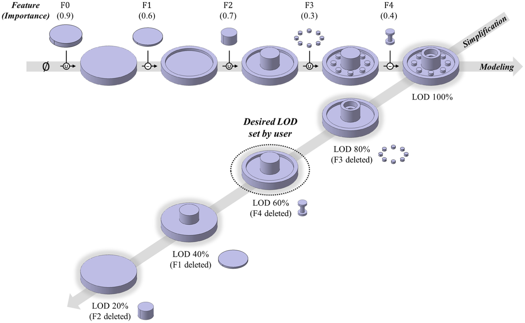
Simplification procedure of a feature-based 3D CAD model.
To select the features to be suppressed, evaluation metrics are used for calculating the quantitative importance of each feature by judging all characteristics of each feature according to the simplification criteria. The evaluation metrics proposed by Kwon et al. 10 were adopted in the proposed system for calculating feature importance. Equation (3) shows the evaluation metrics

where


The features fall into one of three ranges based on equation (3): features that must be maintained
3D shape comparison: shape distribution-based method
The shape distribution-based method proposed in Ohbuchi et al. 12 was adopted to compare an original model with simplified models. This method calculates a distance-and-angle pair from the randomly selected two points among the point cloud regularly generated on the surface of the 3D shape. The two-dimensional (2D) probability distribution function (PDF) calculated from a set of distance and angle pairs are used as a shape descriptor for each 3D CAD model. Finally, the quantitative similarity between two 3D CAD models can be obtained by comparing the PDFs of two 3D CAD models.
This method has the following advantages: First, it can be applied to various types of 3D CAD models, including mesh, B-rep, and feature-based models because it requires only the point cloud of a 3D CAD model as input data. Second, scale invariant comparison is possible through the normalization of translation and rotation. Third, the algorithm is simple enough to finish the computation in a short span of time. That is the reason for the adoption of the shape distribution-based method in this study.
Figure 4 shows the process for generating a shape descriptor for a 3D CAD model in the shape distribution-based method. The shape distribution-based comparison method requires a point cloud sampled from a model. To do this, we converted a feature-based model into a mesh model via a B-rep model. Then, the uniformly distributed point cloud set S is created on the surface of the converted mesh model. Next, the normal vector set N is obtained for all points in S. The normal vectors corresponding to the points can be easily calculated by vector product, and the definition of the shape function ensures reliable comparison although the direction of the vector reverses due to the defects of some models. The point sampling is repeated M times, which is determined by a user. For each repetition, two points and corresponding normal vectors are randomly selected from S and N, respectively, and shape function AAD is calculated as shown in Figure 5.
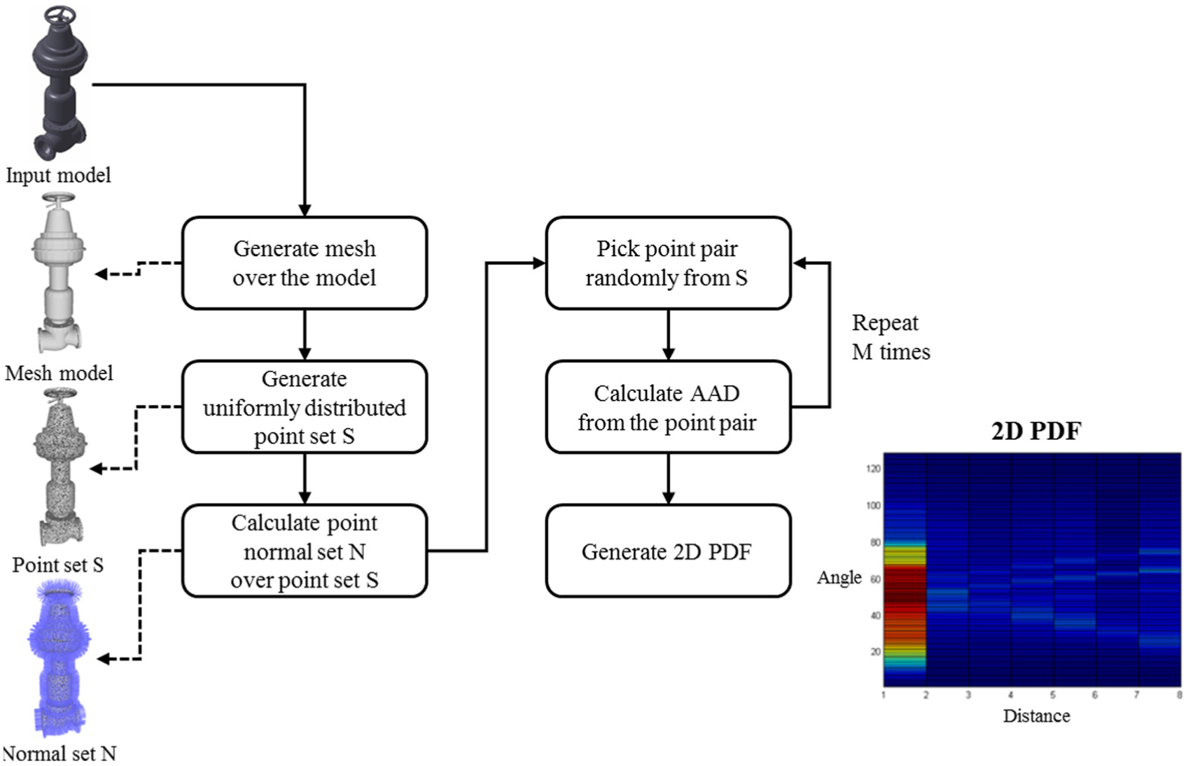
Generating a shape descriptor based on the shape distribution.

Calculation of the shape function AAD.
Finally, 2D PDF can be obtained by dividing the distances and angles by the fixed number of intervals and calculating the frequency of occurrence. Two axes represent distance and angle, respectively, and the brighter color represents higher occurrence for a certain range of distance and angle pairs as shown in Figure 4. The 2D PDF becomes a shape descriptor for a 3D CAD model. To compare 2D PDFs of two models, a metric is required for calculating the quantitative distance between shape descriptors. Therefore, the Minkowski L1 norm was adopted for this study.
Experiments and verification
Test cases
Five test cases were selected to verify the proposed method in this study. Figure 6 shows the original shapes: butterfly valve, air compressor, engine blower, pump, and hydrophore. They are equipment models that are commonly used in the various industries where automated simplification is needed. They were modeled using a commercial feature-based 3D CAD system (CATIA V5 R20). To generate shape descriptors during simplification, feature-based models are converted into mesh models first, and then uniformly distributed point clouds are sampled on the mesh. The point clouds become the input for generating shape descriptors afterwards.

Test cases used for experiments.
Automatic determination of appropriate LODs for test cases
The experiments were conducted using three test cases. Simplified models for each test case were created using the feature-based simplification method. A total of 13 LOD models were created for each test case, 8 LOD models from LOD 100 to LOD 30 in intervals of 10, and 5 LOD models from LOD 30 to LOD 25 in intervals of 1. When the original model has changed, a simplified model for the changed model can be automatically generated without user intervention assuming that the permissible dissimilarity is the same.
Figure 7 shows the simplification results for the test cases. The invisible parts were set as negative terms in equation (3), and detected automatically using the ray casting method. 1 The invisible parts were therefore removed earlier than other features since they had relatively lower importance. As LOD for each test case decreases, local features, such as fillet, chamfer, and hole, get removed in the early stage of simplification, which makes the 3D shape of each test case look simpler than the original 3D shape. The results showed that the outer shapes of the test cases were preserved while local features and invisible parts are removed.

Simplified models with different LODs for test cases.
For each LOD model of the test cases, 10,000 points and their corresponding normal vectors were generated. Next, a histogram was created using 64 bins for distance and 8 bins for angle, and then converted to a PDF. For scale-invariant similarity measures, the bin intervals for distance were adaptively defined using the maximum distance from each model. The similarity value varies from 0 to 2; 0 means 100% similarity, whereas 2 means 0% similarity.
Figure 8 depicts the similarity evaluation matrix for the test cases that shows the similarities between an original model and its simplified models with different LODs. The row stands for the original models (LOD 100), and the column for the simplified models. One grid shows the similarity between two models (original and simplified), the darker grid means the higher similarity, while the lighter means the lower similarity. As shown in Figure 8, CAD models belonging to the same test case show relatively higher similarities and CAD models of different test cases show fewer similarities. It was also found that similarity reduces as the LOD of the 3D CAD model for each test case decreased.

Similarity evaluation matrix for the test cases.
The graph in Figure 9 shows the dissimilarities between the original model and simplified models. For all test cases, dissimilarities steadily increased as the LOD of a simplified model decreased. The increasing gap between the LODs differs from model to model.

Dissimilarity between an original model and simplified model for test cases when LOD of a simplified model gradually decreases.
Based on the user’s experience, the permissible dissimilarity in equation (1) was set to 15% in this experiment. After acquiring the value of dissimilarity as an input, the algorithm in Figure 2 calculates the appropriate LOD for each test case. The test cases’ appropriate LODs are different since the increasing rates of dissimilarity differ from model to model. The appropriate LODs, the 3D shapes, and the data sizes for the test cases are shown in Figure 10.
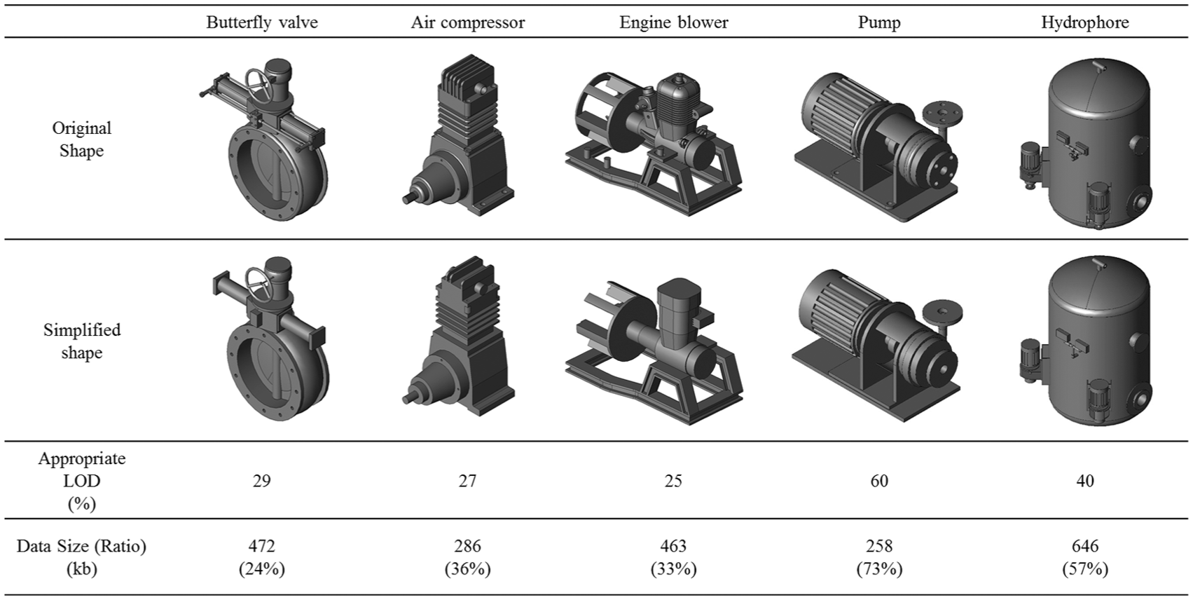
Simplified models at appropriate LODs for the test cases.
Discussion of experimental results
The appropriate LODs varied from LOD 25 to LOD 60 in all test cases. This depends on the permissible dissimilarity, and the model itself. In most cases, the outer shapes were well preserved compared to the original models, except for the details. The data sizes were decreased by 45% on average. In an older study, 1 which used three identical test cases (butterfly valve, air compressor, and engine blower), a user determined the appropriate LODs manually, which were 31%, 25%, and 22%. Compared to the previous study, the average difference was approximately ±2.3%, which appears to be far from significant. From the experimental results, it could be concluded that the proposed method works effectively for the determination of the appropriate LOD of a 3D CAD model.
The contribution of this study is that a user does not have to determine the appropriate LOD of a given 3D CAD model during the simplification phase; instead, a new method proposed by the study automatically determines the appropriate LOD of a 3D CAD model using simplification and shape comparison methods. The usefulness of the proposed method will be especially maximized when a number of models need to be simplified in a batch-processing mode, or when a range of appropriate LODs need to be recommended to a user.
Conclusion
Users traditionally are required to determine a desired LOD themselves, during the simplification of the 3D CAD model. However, there are cases in which the appropriate LOD for each 3D CAD model should be calculated automatically as mentioned earlier.
This article has proposed a new and automated method to determine the appropriate LOD of 3D CAD models without users’ intervention during simplification. To achieve this goal, the concept of appropriate LOD for simplification was defined from the viewpoint of shape dissimilarity. After that, an algorithm to determine the appropriate LOD of a model was developed by adopting the feature-based simplification method and the shape distribution-based comparison method. However, the adoption of the two technologies may vary depending on the field of application.
A prototype system was implemented based on the proposed method, and the proposed method was verified through experiments in which the appropriate LODs for test cases were automatically determined by the system. The appropriate LODs calculated were different according to the test cases. In most cases, the outer shapes were well preserved when compared to the original models, except for local details. In addition, the appropriate LOD of each test case determined in this study was similar to the LOD of the same test case manually determined in an older study. 1
The key contribution of this study is that the simplification system automatically calculates an appropriate LOD based on the shape dissimilarity between an original shape and its simplified shape; the shape dissimilarity is the most commonly considered factor when a user determines the LOD for a 3D CAD model in the simplification process. The proposed method is essential when we want to simplify multiple models in a batch-mode or complete the simplification automatically without user intervention. However, each step of model simplification involves shape similarity comparison, which naturally leads to the increase in total time required.
In the future, we will improve the developed simplification system so that an appropriate LOD for a specific model is calculated more accurately by applying other local shape descriptors such as FPFH 31 or SHOT 32 that give better comparison results than shape distribution-based method. Furthermore, we will improve the simplification system to handle B-rep and mesh models by applying B-rep-based and mesh-based simplifications to the proposed method.
Footnotes
Academic Editor: David R Salgado
Declaration of conflicting interests
The author(s) declared no potential conflicts of interest with respect to the research, authorship, and/or publication of this article.
Funding
The author(s) disclosed receipt of the following financial support for the research, authorship, and/or publication of this article: This research was supported by the Kyungpook National University Bokhyeon Research Fund 2015, by the Industrial Core Technology Development Program (Project ID: 10063452) funded by the Ministry of Trade, Industry and Energy of the Korean government. The authors gratefully acknowledge this support.