
Abstract
The longitudinal–torsional ultrasonic vibration machining process is popular for machining hard and brittle materials. A longitudinal–torsional ultrasonic vibration system with diagonal slits was designed for the ultrasonic vibration machining process based on the principle of acoustics propagation in this study. Four uniform diagonal slits were cut off on the horn cylinder to transform the longitudinal ultrasonic vibration into a longitudinal–torsional composite motion. A finite element analysis was used to optimize the mechanical structure of the vibration system. Dynamic characteristics of the vibration system were numerically studied, and the relationship of diagonal slits versus the resonance frequency and amplitudes of longitudinal–torsional vibration was analyzed, so that the longitudinal–torsional output amplitude can be optimized by rational choice of structure parameters of diagonal slits. Moreover, the movement locus of the system output end was obtained by utilizing the Origin software, which was proved to be elliptical, and the accuracy of the finite element model was confirmed by comparing numerically and experimentally determined resonant characteristics. In addition, the verification of longitudinal–torsional ultrasonic vibration was proved for the designed ultrasonic vibration system.
Keywords
Introduction
Along with widespread use of various advanced materials (such as carbon fiber composite and ceramics) in various industrial sectors such as aerospace, military, precision machinery, and electronics, the machining processes of these materials become one of the research hotspots in the mechanical industry. Moreover, these materials often have various intractable characteristics such as high hardness, high strength, thermo-stability, wear resistance, and corrosion resistance. The traditional machining processes encountered many problems such as low efficiency and relatively poor surface quality. It is necessary to develop precise machining technology to raise working efficiency and improve surface quality. However, the ultrasonic vibration machining process which is to convert ultrasonic electric signals into mechanical vibration amplitude has been being very popular in the machining field. Since the introduction of ultrasonic vibration, many benefits can be obtained such as changing the material removal mechanism, reducing the cutting force and the friction between the tool and the workpiece, reducing the cutting temperature, improving tool life and the precision and quality, and enhancing the cutting capacity of the tools, thus effectively improving material removal rate.1–5
According to previous research, several methods were used to develop a two-dimensional (2D) ultrasonic vibration system such as longitudinal–torsional, longitudinal–bending, and bending–torsional vibration methods. Currently, the longitudinal–torsional ultrasonic vibration can be generated primarily by utilizing the following methods along with descriptions:
Tangential polarized piezoelectric transducers:6,7 there are two different poled piezoceramics (one in the axial direction and the other in the tangential direction), which are excited separately so that the frequency-matching relationship between the two resonances may be difficultly maintained under various load conditions. Moreover, processing the tangentially poled piezoceramic is not easy; in addition, its limited output power does not conform to large power demand popular turning and grinding processing technology.
Circumferential magnetostrictive torsional transducers: 8 the output power of this kind transducer is also limited and not suitable for high-power milling machining. The transducer can achieve high amplitude with more heat generated. So it is needed to equip a cooling module.
Longitudinal torsion push–pull vibration device (ultrasonic horns): it may be used in high-power ultrasonic applications. However, its common complicated structure limits its rotary ultrasonic machining application.
Spiral groove–type vibration device: 9 the vibration frequency of this vibration device depends too much on the characteristics of spiral groove, and the machining process is very complicated.
Longitudinal–torsional vibration device with diagonal slits (ultrasonic horn with diagonal slits): 10 the resonance frequency equation presented by Lin 11 can be regarded as design theoretical basis in the same frequency. J Pi 12 derived the state of plane principal stress in diagonal slits with longitudinal stress wave reflecting principle to diagonal slit, and the resonance frequency equation was represented by means of the equivalent circuit. Park et al. 13 used finite element (FE) analysis to optimize the mechanical structure of the longitudinal–torsional ultrasonic motor with diagonal slits. Yang et al. 14 put forward a longitudinal–torsional ultrasonic vibration system whose wire drawing was designed by the use of the four-terminal network and carried out analysis of its relationship between resonance frequency and longitudinal and torsional amplitude based on selection of structure parameters. Asami and Miura 15 designed a hollow-type stepped horn with diagonal slits and a uniform rod with diagonal slits for hole machining brittle materials. The relationship between the two different processing devices and the hole machining characteristics was established and experimentally verified based on choice of the vibration amplitude and the cross-sectional area ratio of vibration sources.
So far, there have been few reports about the accurate design method for the ultrasonic horn with diagonal slits, especially theoretical analysis of the relationship between the longitudinal and torsional vibration characteristics and the shape of diagonal slits.
This study focuses on design and analysis of a longitudinal–torsional ultrasonic vibration system, in which an ultrasonic transducer matched the horn, and the system resonance frequency was designed as 20 kHz based on the longitudinal wave propagation equation set. Therefore, theoretical calculation and simulation analysis are combined in this design. Moreover, the single-factor experiments were carried out to verify the simulated relationship between the longitudinal and torsional vibration characteristics and the shape of diagonal slits.
Description of design
Ultrasonic vibration system
The ultrasonic vibration system is made up of an ultrasonic transducer, an ultrasonic horn, and a machining tool. Due to there being a variety of cutting tools and their little effect on the system resonant frequency, only the assembly of ultrasonic transducer and horn are designed and analyzed. The ultrasonic transducer with input of sine voltage signal derived from an ultrasonic generator creates reciprocative harmonic motion with high frequency and low amplitude. Then, the vibration amplitude is amplified by the horn (types: conical, exponential, catenoidal, and stepped), which is to attain desirable vibration amplitude values. A stepped horn takes advantages of larger displacement amplification and no stress concentration in comparison with those of a conical horn, and such advantages are integrated into our composite horn. The system resonance frequency is 20 kHz, and the ultrasonic transducer and the ultrasonic horn are a half of the system wavelength in length.
Ultrasonic transducer
Ultrasonic transducers can be divided into two categories: piezoelectric and magnetostrictive transducers. The former are popular in the ultrasonic vibration machining field with the higher amplitude requirement due to their advantages such as small sizes, large output amplitude, impedance matching, and high energy conversion efficiency.
Generally, a sandwich transducer suitable for high-power ultrasonic applications is composed of piezoelectric ceramics, a front cover in contact with the load and a rear cover usually in contact with air. While the piezoelectric ceramics are applied with an alternating voltage, an alternating deformation will occur. For convenient analysis, reasonable simplification was carried out to the complicated structure of the sandwich piezoelectric transducer. The simplified model is shown in Figure 1.

Simplified model of transducer.
The 45 steel is used for the rear cover. The piezoelectric ceramics are lead zirconate titanate (PZT-4) with large tensile strength and stability. The rest parts are manufactured by hard aluminum. In this case, the back end is much heavier than the front end. It is beneficial to transfer ultrasonic energy forward efficiently. Table 1 lists the parameters of the material properties.
Parameters of material properties.

PZT-4: lead zirconate titanate.
Two PZT-4 piezoelectric ceramics compressed through the middle axle with the rear cover should be polarized in opposite directions, and the interface between the front cover (length: a quarter of the wavelength, namely, l3 = 63 mm) and piezoelectric ceramics is the node-section of the transducer (diameter: 52 mm). A sandwich transducer with uniform cross section is usually considered as a two-quarter wavelength vibrator. According to the principle of stress and velocity continuous transmission, the resonance frequency equation of the left part of the nodal surface is expressed by16,17

where
As for ultrasonic vibration machining applications, the thickness of a piezoelectric ceramic is generally 5–10 mm. Paired piezoelectric ceramics are generally utilized. A pair of piezoelectric ceramics (thickness: l2 = 12 mm) is used here. Based on the above parameters and the resonance frequency from equation (1), the length of the rear cover is l1 = 36 mm.
Ultrasonic horn
The large-end diameter of the horn is same with that of the transducer, and the small-end diameter can be specified as 16 mm based on the amplification factor and the tool size. The half-wavelength composite (conical-stepped) horn was designed in accordance with the one-dimensional (1D) longitudinal vibration theory. The structure schematic diagram of the composite horn is shown in Figure 2. According to Zhao et al., 17 the resonance frequency equation of a composite horn with variable cross section can be expressed by

where

Structure schematic diagram of the composite horn.
The node-section is the interface between the cylinder and the cone. A hollow-type stepped horn (hollow part: depth: 24 mm and diameter: 8 mm) is designed for easily installing tools. By taking L1 = 65 mm and L2 = 30 mm, the length of the right part can be obtained (L3 = 56 mm) by equation (2). The flange is used to fix the ultrasonic vibration system, and it should be rationally selected because too small dimension leads to insufficient stiffness and too large dimension results in relatively large energy loss. The value of the flange thickness is specified as 3 mm based on experiences from relevant literatures, and the flange is located at the node-section of the horn.
Design of longitudinal–torsional vibration
Several uniformly distributed diagonal slits in the front cylinder end of the horn generates the longitudinal–torsional composite vibration in this study. The structure principle chart of longitudinal to torsional vibration converter with diagonal slits is shown in Figure 3. As there are slanting slots on the horn cylinder, the longitudinal vibration created by the transducer will be partially converted into torsional vibration. Therefore, longitudinal and torsional vibrations will coexist in the end of the horn, and longitudinal–torsional compound vibration will be produced. Specifically, the reflected longitudinal and shear waves rather than the secondary refraction only take effect due to the large energy loss for propagation of longitudinal wave in air. Slits reflect coming longitudinal waves. There is a certain angle between the reflected longitudinal and shear waves and the rod axis to produce axial and tangential wave components bringing about the longitudinal and torsional vibrations in the output end, which can be combined to produce an elliptical trajectory of displacement.

Structure principle chart of longitudinal to torsional vibration converter with diagonal slits.
It is obvious that the characteristics of the slanting slots such as the tiled angle, the position, and the dimensions will have influences on the performance of longitudinal–torsional vibration. Section “FE analysis of the ultrasonic vibration system” will present the effects of the characteristics of the slanting slots using finite element method (FEM). In order to facilitate experimental study of the ultrasonic vibration system, the initial parameters of diagonal slits are as follows: length: 10 mm; width: 2 mm; tilted angle: 45°; depth: 4 mm; distance x from the output end: 10 mm; and number of the diagonal slits: 4. Machining the flange and diagonal slits may lead to changes in the resonance frequency of the horn. The three-dimensional (3D) model of ultrasonic vibration system is established in software UG (Unigraphics NX), and then the model is imported to ANSYS for modal analysis by properly varying the small-end length while other structure sizes remain unchanged. When the small-end length is 57.5 mm, the longitudinal resonance frequency of the assembly is 20.002 kHz.
FE analysis of the ultrasonic vibration system
It is imperative to have a physically substantiated numerical model enabling accurate predictions of dynamic behavior of the vibration system. FE software ANSYS was applied for the development of a detailed 3D numerical model of the horn incorporating piezoelectric transducer (Figure 4). The purpose of the FE analysis was to reproduce the actual prototype of the vibration system as accurately as possible.
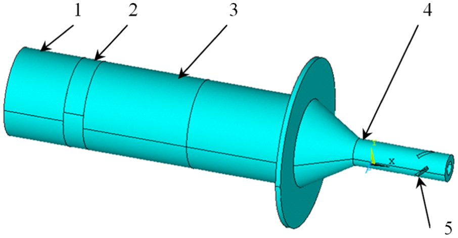
Structure diagram of the longitudinal–torsional composite vibrator.
Modal analysis
Modal analysis is to determine the vibration characteristics (namely, the natural frequency and vibration mode) of the system or parts. Solid 5 Element with up to 6 degrees of freedom (DOF) at each node is used to mesh piezoelectric ceramic parts; the mode number is 20 and the region for searching the mode frequency is 15–25 kHz. It is assumed that there is no external system load under the free boundary conditions for performing the modal analysis, and the fast and popular block Lanczos method is used for modal extraction. The closest frequency (20.002 kHz) may be extracted from the longitudinal resonance frequency and the corresponding vibration mode is shown in Figure 5.

Longitudinal vibration modal.
To research the effects of the characteristics of the slanting slot (such as the tiled angle, the position, and the dimensions), a series of analyses (only one parameter can be varied to satisfy the single-variable rule) were carried out to analyze the natural frequency of the horn while diagonal slits are of different sizes, which are presented in Table 2. All of the analyses with a total of 25 simulations were divided into five groups with different parameters of the slanting slot.
Different sizes of diagonal slits.
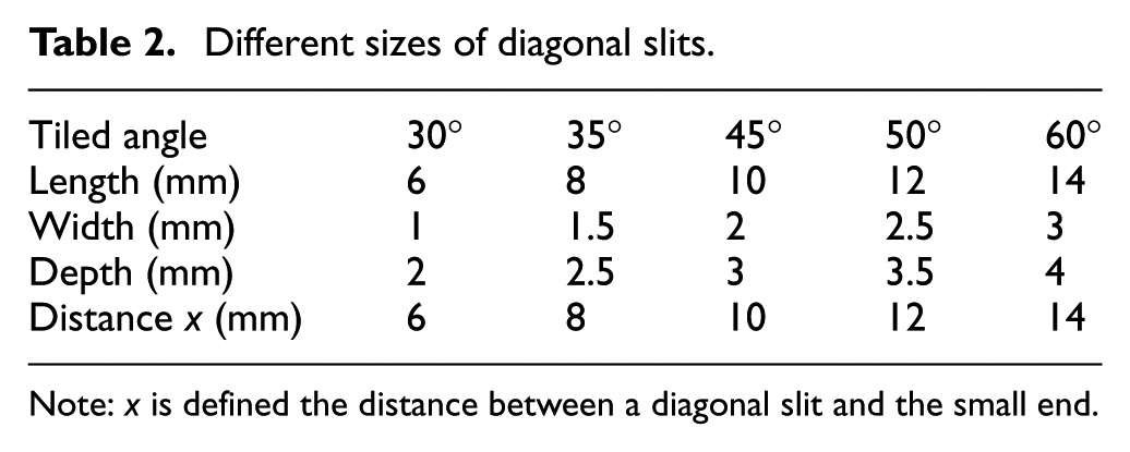
Note: x is defined the distance between a diagonal slit and the small end.
The following results can be generalized from Figure 6: the resonance frequency is not basically influenced by the width and depth. The resonance frequency falls correspondingly along with the increase in the tilted angle or the distance x and their effects are relatively weak; however, the resonance frequency is influenced much greater by the length. Thus, it is the length that shall be regarded as the major influence factor of the resonance frequency.

Resonance frequency versus sizes of a diagonal slit.
Harmonic response analysis
Harmonic response analysis as a method for determination of the structure’s steady-state response under any load changing as sine wave with time is to calculate some structure response values (generally expressed by displacement–frequency response curves) under several frequencies. While a sinusoidal voltage is applied exactly to the system, piezoelectric coupling analysis is carried out by means of ANSYS to obtain the displacement-frequency response curve at the output end and verify the resonance frequency from the modal analysis. The load (voltage) for the harmonic response analysis is due to the mechanical vibration output of the transducer being not simulated while an independent displacement being loaded.
The flange is fixed and the voltage is applied to two pieces of piezoelectric ceramics (center: 100 V and both sides: 0 V) in opposite directions while performing fast and exact full-method analysis (the solving frequency range: 19–21 kHz and the number of steps: 500). Results of the intersection point P between the X-Z plane and the small-end edge are extracted in TimeHist Postproc after the calculation. The harmonic response analysis results are shown in Figure 7, where, UX, UY, and UZ represent 3D displacement responses of point P with frequency, respectively. The vibration displacements in various directions are close to their maximum values while point P approximates its peak frequency (20.002 kHz); such conclusions are the same as those of modal analysis. The amplitude ratio of the longitudinal and torsional vibrations (UX/UY) is obtained; at the same time, the relationships between the output amplitude and UX/UY and sizes of diagonal slit are verified by the single-factor experiments.

Displacement response of point P in (a) X-direction, (b) Y-direction, and (c) Z-direction.
The relationship of the output amplitude versus sizes of a diagonal slit is shown in Figure 8. The longitudinal vibration amplitude significantly impacted by length and depth to some extent is complicated and difficult, controlled by varying sizes of a diagonal slit. Moreover, the output longitudinal amplitude is enlarged along with the increasing distance x, which determines the amplitude of transformation. The depth and the tiled angle shall be sufficiently taken into account to get a large output longitudinal amplitude while designing diagonal slits.

Output amplitude versus sizes of a diagonal slit.
The relationship of UX/UY of point P versus sizes of a diagonal slit is shown in Figure 9. The smaller UX/UY is, the larger the proportion of conversion from the longitudinal vibration to the torsional vibration. UX/UY remains basically constant while changing the width or the tiled angle; however, UX/UY is remarkably influenced by changing the depth; moreover, UX/UY is also greatly affected by changing the length or the distance x; in addition, UX/UY rises along with the increase in distance x. Thus, length, width, and distance x shall be sufficiently taken into account to meet machining requirements.

UX/UY versus sizes of diagonal slits.
According to above analysis results and for gaining the relatively large longitudinal and torsional vibrations, the sizes of the diagonal slits are as follows: length: 10 mm; width: 2 mm; tilted angle: 50°; depth: 4 mm; and distance x: 10 mm.
Transient dynamic analysis
The fast and exact full-method transient dynamic analysis is to determine the dynamic response of any structure applied with any load changing with time. A sinusoidal voltage is applied here to piezoelectric ceramics to observe the displacement response of the output end with time; at the same time, the locus diagram can be obtained in any location of the output end where the 2D elliptical vibration is verified. The displacement load was used in previous transient dynamic analysis; however, the actual load is sinusoidal voltage. The voltage to the piezoelectric ceramics center is
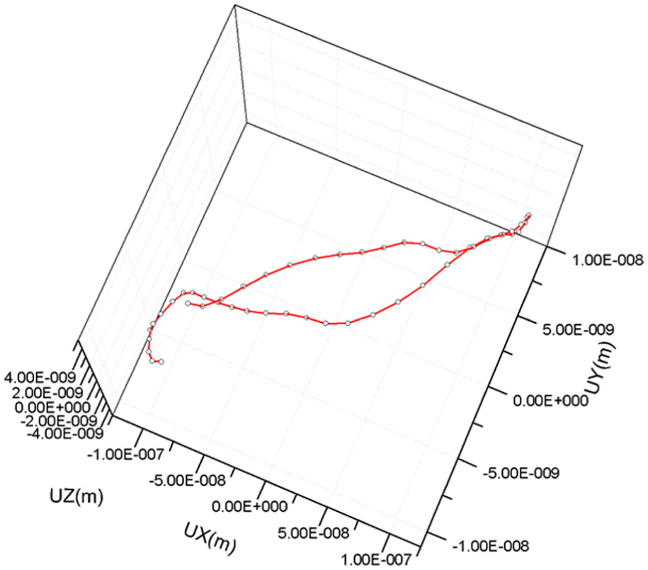
Movement locus of point P.
Experimental results and discussion
Measurements of dynamic characteristics of the developed ultrasonic vibration system were performed with the goal to clarify the key aspects of the system vibrational behavior. The piezoelectric transducer of the ultrasonic vibration system was driven harmonically using function generator (Model AFG3022C, Tektronix, USA). A constant excitation voltage was maintained with a power amplifier (Model 1040L, E&I, USA). An impedance-matching instrument (Model Lo-Hi-Z-8-500, E&I, USA) was connected between the power amplifier and the ultrasonic vibration system in order to match impedance.
A laser Doppler vibrometer (Model LV-S01-ST, Sunny Instruments Singapore Pte Ltd, Singapore) was used to measure the vibration amplitude of the ultrasonic vibration system. A data acquisition and analysis system software (Model quicksa, Sunny Instruments Singapore Pte Ltd, Singapore) was dedicated to the acquisition and processing of vibration measurement data, it used to measure data into real-time collection and storage, analyze and save the data by recording to the computer. Figure 11 shows the block diagram of measurement procedure, and Figure 12 shows the photo of the experimental setup.
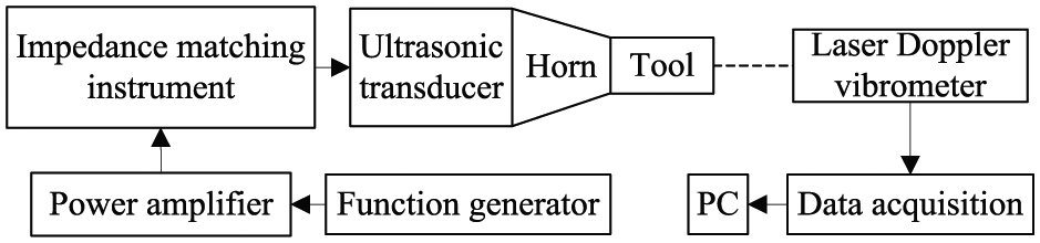
Block diagram of measurement procedure.

Photo of the experimental setup.
Ultrasonic longitudinal–torsional vibration includes longitudinal and torsional directions; therefore, different measurement methods were needed to be carried out to measure the vibration amplitudes of the ultrasonic vibration system.
The signal emitted from laser head was vertically radiated to the end face of the cutting tool pasted with reflective paper for measuring longitudinal vibration. However, in order to effectively measure the torsional vibration, the end face of cutting tool was cut into a flat shape. The laser head was placed on the side of the tool, and the signal emitted from laser head was vertically radiated to the edge of the flat surface to measure the torsional vibration.
Measurement results were provided in Figures 13 and 14. The maximal achievable amplitudes of longitudinal and torsional vibrations are
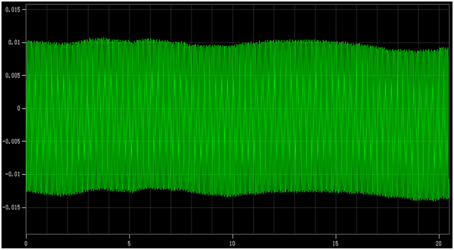
Measurement result of longitudinal vibration.

Measurement result of torsional vibration.
Conclusion
A 2D ultrasonic vibration system is much popular in the power ultrasonic vibration machining. A kind of longitudinal–torsional horn with diagonal slits was designed for ultrasonic vibration machining process in this study. To reduce the time and cost involved in the mechanical and electrical design processes, characterizing dynamic behavior of the vibration system was studied through numerical and experimental approaches. Modal and dynamic analyses were carried out by means of ANSYS based on the actual sinusoidal voltage load rather than the previous displacement load for transient dynamic analysis. Relationships of the longitudinal–torsional resonance frequency and amplitude versus sizes of diagonal slits were studied to verify that the longitudinal vibration can be converted into the torsional vibration in the output end of the horn with multiple diagonal slits, and the locus of output end is elliptical. The amplitude of torsional vibration is mostly affected by the length of diagonal slits. In order to have large torsional vibration, the slits length should be large enough. Length of diagonal slits and the distance x play critical roles in the longitudinal–torsional vibration of the vibration system. Rational choice of sizes of diagonal slits can optimize the longitudinal–torsional output amplitude. Moreover, accuracy of the FE model was confirmed by comparing numerically and experimentally determined resonant characteristics.
Footnotes
Academic Editor: Jianqiao Ye
Declaration of conflicting interests
The author(s) declared no potential conflicts of interest with respect to the research, authorship, and/or publication of this article.
Funding
The author(s) disclosed receipt of the following financial support for the research, authorship, and/or publication of this article: This study was funded by the Science and Technology Department of Hubei Province (grant number: 2015BAA022) and the State Key Lab of Digital Manufacturing Equipment and Technology (grant number: DMETKF2015014).