
Abstract
To tackle the excessive output torque ripple during engine starting process of parallel hybrid electric vehicles, the engine starting process is divided into three phases in this study: engine cranking phase, speed synchronization phase, and after synchronization phase. The expressions of the vehicle jerk are derived from the vehicle dynamic formula in each phase, and the influences of various parameters on the jerk are analyzed. The coordinated control strategy for the clutch pressure and motor torque and that for the motor torque and engine torque are proposed. The simulation model for the single-motor parallel hybrid electric vehicle is established using MATLAB/Simulink, and the effectiveness of the proposed control algorithms is verified. Besides, a bench test is conducted and the test results show that the selected change rates of clutch pressure, motor torque, and engine torque can effectively coordinate the relation between clutch, motor, and engine. It can be concluded that the proposed control strategy satisfies the requirement of vehicle ride performance in engine starting in-motion process.
Keywords
Introduction
Hybrid electric vehicles (HEVs) represent an effective solution to significantly reduce the consumption of fossil fuels and carbon emissions 1 which have two or more mechanical power sources and have different driving modes for different driving situations, such as pure electric driving mode for low vehicle speed. To make full use of the plug-in hybrid electric vehicle (PHEV) powertrain, frequent transitions between different modes are necessary to optimize the vehicle operation.2–4 When switching mode from pure electric driving mode to engine driving mode, the internal combustion engine needs to start in motion. During this process, the total torque of powertrain may experience a big change if there is no appropriate control in place, and it is highly likely to cause a torque fluctuation to the powertrain as well as a jerk to the vehicle. Thus, how to devise an appropriate torque coordinated control strategy has become one of the key problems in HEV design. In this article, we put forward a torque coordinated control strategy to reduce the jerk. This method employs the torques of different parts as the control parameters and coordinates the change rates of clutch, motor, and engine to ensure smooth engine start.
Various solutions have been proposed in the literature to tackle the above-mentioned problem. The causes of jerk have been analyzed and discussed through various experimental tests. 5 Y Tong6,7 put forward a dynamic coordinated control method, that is, “the open control of engine torque”+“the estimate of engine dynamic torque”+“the compensation of motor torque.” But in practice, the engine dynamic torque is hard to estimate. E Ji 8 and Y Wang 9 proposed a method to limit the engine torque changing slope and use the motor torque as compensation, but the method is only effective in after synchronization phase. Y Yang et al. 10 controlled the engine torque using a proportional–integral–derivative (PID) controller and controlled the clutch using a fuzzy control algorithm; however, this method also needs the real-time engine torque information. Unfortunately, this approach cannot be commonly used due to patent protection. J Zhang et al. 11 proposed a new algorithm which realizes smooth mode switching from pure electric driving mode to engine operating mode. This algorithm obtains engine pseudo-target speed according to speed and throttle opening, but the engine is treated as a quick torque response machine, and the control algorithm has only been verified by simulation. J Sun et al. 12 used model predictive control (MPC) methods to coordinate the clutch, motor, and engine. In his study, the clutch is taken as an optimized variable and the clutch friction loss is taken into consideration. The simulation results show that the proposed control strategy has less vehicle jerk and less clutch friction loss. L Wang 13 improved the driving comfort by means of the adaptive sliding mode control technique. In this work, the error caused by the system parameters’ uncertainty and error between the actual engine torque and engine target torque are estimated, and these errors are employed as the control variable of the sliding mode controller. J Oh et al. 14 and M Yang et al. 15 focused on the estimation of the engine clutch torque and proposed estimation algorithm as well as control method. D Kum 16 proposed optimal control strategy of engine-start process that achieves the balance between drivability and quick start.
The above works mainly focus on how to estimate the transient engine torque and how to control the engine or clutch. However, the key to the problem is to find out the coordinated relationship between the engine, motor, and clutch. This article analyzes the dynamic equations of the engine starting in-motion process and obtains the relationship between the clutch pressure change rate and motor torque change rate before synchronization as well as the relationship between engine torque change rate and motor torque change rate after synchronization. Then, the control feasible regions are pointed out, and the control strategy based on the control feasible regions is proposed. Furthermore, in the control strategy, (1) the engine ignition shock has been avoided by igniting the engine before speed synchronization and (2) the clutch torque abrupt change has been properly managed in the synchronization phase. Both the simulation results and test results verify that the coordinated control strategy is effective in reducing the jerk and improving the ride performance.
A single-motor parallel HEV is considered in this study, as shown in Figure 1. In this vehicle, a clutch is installed between the engine and the motor. The vehicle is in the pure electric driving mode (EV mode) when the clutch is disengaged. This HEV has several driving modes, including the EV mode, engine-only driving mode, and hybrid mode (the motor works as a traction motor or a generator). During start-up or at low vehicle speed, only the motor drives the vehicle (EV mode) while the engine is shut down to increase the fuel economy and to reduce emissions. When the vehicle speed reaches a certain value (or other situations), the motor needs to start the engine. As the clutch engages and the engine speed increases after ignition, the engine-only driving mode or both the engine and motor (hybrid mode) drive the vehicle. The transition from the pure electric driving mode to the engine mode or hybrid mode is called “engine starting in-motion.”
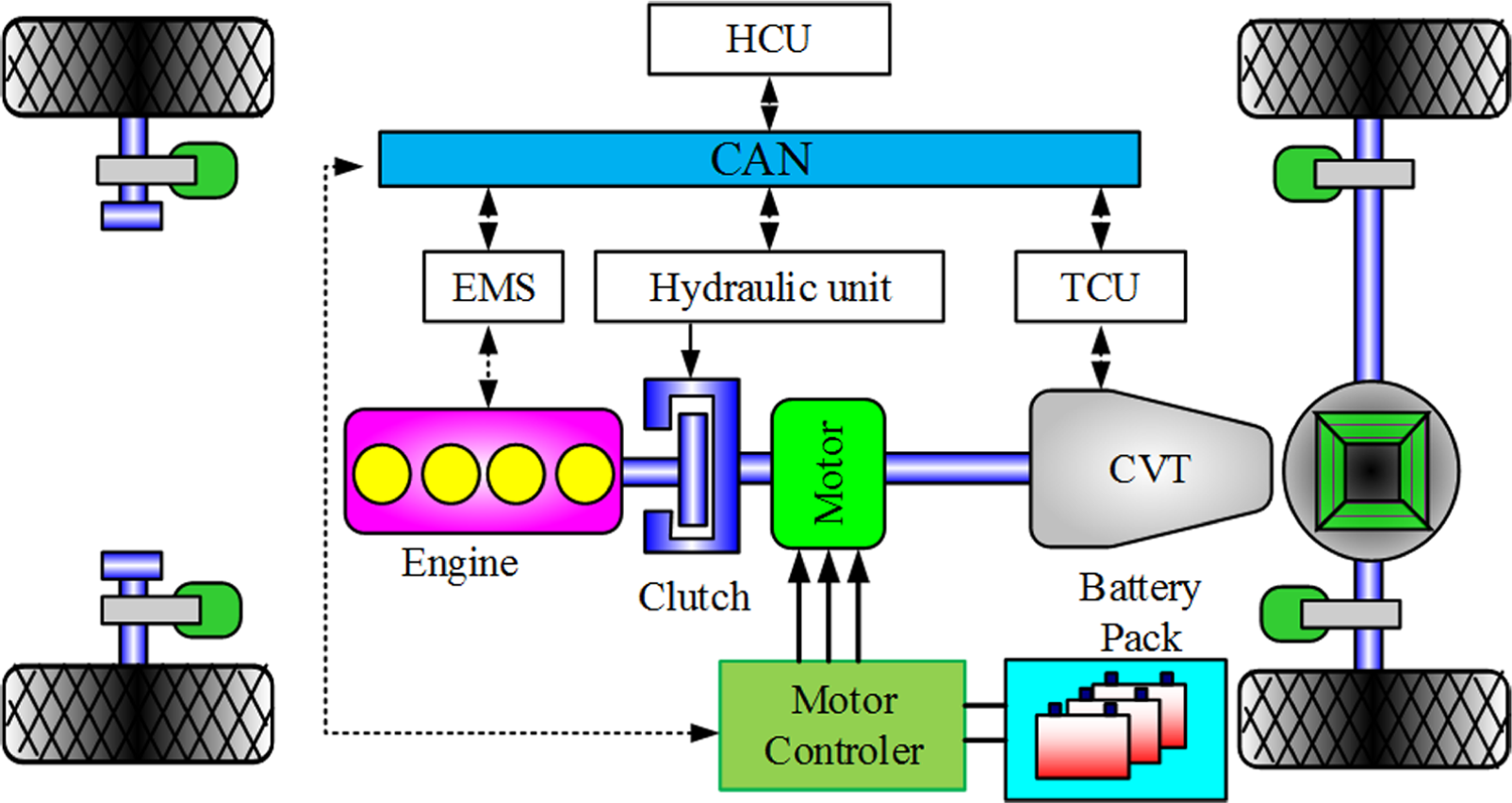
Structure of the single-motor parallel HEV.
The rest of the article is organized as follows. Section “Characteristics of the key components” explains the characteristics of the key components. Section “Dynamic equations for engine starting in-motion” divides the engine starting process into three phases, and dynamic analysis is performed for each phase. Section “Vehicle jerk analysis” presents the control relationship of the engine, motor, and clutch, resulting from the vehicle dynamic equations. In section “Control strategy and simulation verification,” the control strategy and HEV model developed by MATLAB/Simulink are introduced. Section “Simulation and experimentation” demonstrates the simulation and bench test results, followed by some discussions about the results. The last section concludes the article.
Characteristics of the key components
To quickly start the engine and minimize the vehicle jerk in the engine starting process, the detailed knowledge of the characteristics of every key component is necessary.
Internal combustion engine characteristics
In order to precisely control the powertrain load torque variation during engine starting in-motion, and to smoothly start the engine, a test bench of a 1.6 L four-cylinder electronic injection engine is built. The test bench evaluates the steady-state engine output torque at the throttle valves of 1%, 2%–40% (at a 2% interval), 45%–95% (at a 5% interval), and 99%, at the corresponding engine speeds of 1000 and 1250–6000 r/min (at a 250 r/min interval) respectively, as shown in Figure 2(a). This bench tests the reverse drag torque at different speeds when the throttle valve is 0%, in order to obtain the loss torque characteristics of the engine, as shown in Figure 2(b).
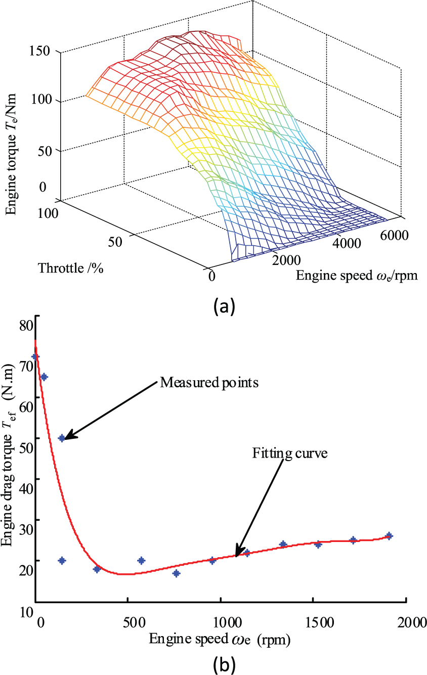
Engine characteristic curves: (a) engine static output map and (b) engine reverse drag torque.
Motor characteristics
To obtain the characteristics of the motor and its controller, a hybrid power system for motor test is designed and a test bench for the motor and its controller is developed. In the test, the motor is running on the limiting condition and the voltage of the DC power supply is set to 288 V. Different parameters (e.g. motor output torque, motor speed, motor efficiency, power supply voltage, power supply current, and inverter efficiency) are tested at motor speeds of 0 and 100–4000 r/min (at a 100 r/min interval).
According to test results, the maximum power, maximum torque, and rated speed of the motor are, respectively, 25 kW, 120 N m, and 2000 r/min. The motor external characteristics is shown in Figure 3

where Tmmax denotes the maximum motor torque and nm represents the motor speed.

Motor external characteristics.
Clutch characteristics
To reduce the fluctuation of total output torque, the clutch needs to engage and disengage gradually when the engine is switched on and off. The knowledge of the clutch transfer torque under different pressure is required, and the clutch must be controlled smoothly and quickly. The clutch torque depends on the pressure and the speed difference between the clutch disks, as expressed by equation (2)

where Tc is the clutch torque, n is the speed difference between the clutch disks, and p0 is the clutch oil pressure.
In order to precisely control the clutch torque, we look into the clutch characteristics by means of experimentation and achieve the clutch torque at different oil pressure and speed difference between clutch disks. The experimental results are shown in Figure 4.

The torque transmission characteristics of clutch.
As seen from Figure 4, the clutch torque is mainly dependent on oil pressure, and the effect of the speed difference between clutch disks is insignificant.
Dynamic equations for engine starting in-motion
Based on vehicle dynamics, the process of starting engine in-motion can be divided into three phases: engine cranking phase, speed synchronization phase, and after synchronization phase. To simplify the control plant, the following hypotheses are made:
Except for the three key components, all other components of the driveline system are rigid bodies and are rigidly connected with each other.
There is no response lag for all components.
With these hypotheses, the dynamic equations for each phase can be derived.
Engine cranking phase
The engine cranking phase is from the beginning of clutch engagement to the beginning of speed synchronization. In this phase, the clutch pressure rises gradually and the clutch enters into the slipping state in which the friction torque is proportional to the clutch pressure. When the clutch friction torque exceeds the engine reverse drag torque at speed 0, the engine crank starts rotating and then the speed difference between the engine and motor reduces gradually. The dynamic equations for this phase are
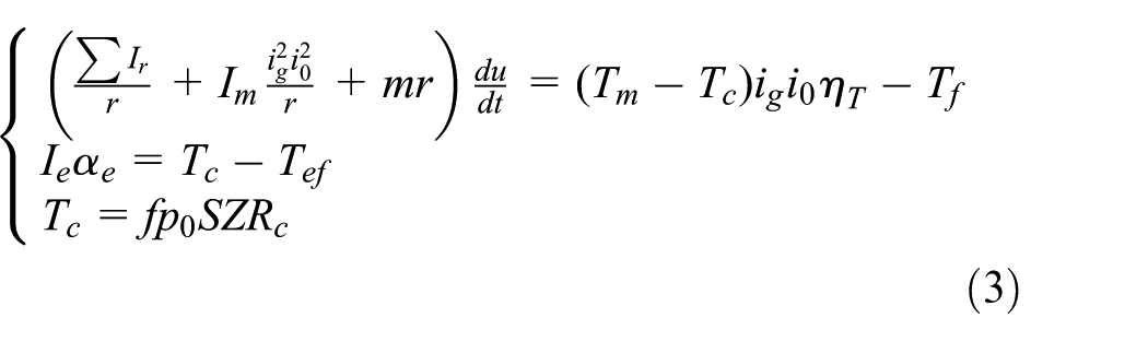
where r is the wheel radius, u is the vehicle speed; i0 and ig are the final drive ratio and transmission ratio; Tm is the motor torque; Tf is the converted total resisting torque; Ir, Ie, and Im are the moment of inertia of the wheel, engine, and motor, respectively; m is the vehicle mass; Tef represents the engine reverse drag torque before ignition;
Since the real-time engine torque is hard to obtain and different engines have different characteristics, we ignited the engine in this phase to ensure that the ignition impact is not transferred to the wheels.
Because the clutch torque mainly depends on the pressure, the engine’s ignition does not change the clutch torque, and the dynamic equations of the powertrain also remain the same. Note that two benefits can result from igniting engine in the clutch slipping condition:
The engine speed increases more quickly, namely the engine accelerating time is minimized.
The engine ignition shock is not delivered to the wheels. 17
After ignition, the engine torque becomes positive and the engine will accelerate itself. However, the clutch disk speed on the engine side is still lower than that of the other disks, and the clutch torque is still determined by the clutch pressure. So only the second equation in (3) is changed to
By this means, the ignition impact can be successfully prevented from being transferred to the wheels.
Speed synchronization phase
In this phase, the speed difference between the clutch driving disk (connected to engine) and the clutch slave disk (connected to motor) is small enough, but the engine is still accelerating. Thus, the dynamic equation before synchronization does not change. When the speed difference becomes zero, the clutch switches its state from slipping to engagement and the speed synchronization is complete. The dynamic equation is now given by equation (4)

Before synchronization, the engine is accelerating to a certain rotational speed and the dynamic equation is
After synchronization phase
In this phase, the clutch is completely engaged and the vehicle is driven by two power sources. Since the engine output torque may be unstable, the motor needs to adjust its torque to compensate for the engine torque variation. So the dynamic equation for this phase is still equation (4).
After compensation, the motor’s operating condition is dependent on the HEV driving mode.
Vehicle jerk analysis
Vehicle jerk analysis before speed synchronization
Before speed synchronization, the dynamic equation does not change, so the vehicle jerk can be obtained by taking derivative of equation (3)

with


where Fr denotes the converted total resisting force, CD represents the air resistance coefficient, and A stands for the vehicle frontal area.
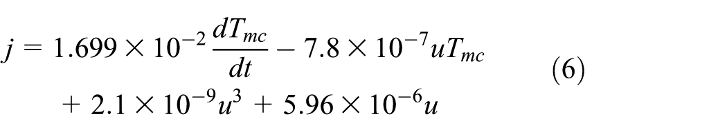
As seen from equation (5), the jerk is mainly dependent on three parameters: vehicle speed, torque difference between the motor and clutch, and change rate of the torque difference. Ignoring the slope resistance and substituting the parameters N, I, M, r, and Fr (depending on vehicle structure) in equation (5) lead to the following expression of vehicle jerk
The influence of each parameter on jerk is shown in Figure 5.

The influence of each parameter on jerk: (a) the influence of vehicle speed and torque difference rate on jerk and (b) the influence of torque difference and its change rate on jerk.
Figure 5 indicates that the torque difference change rate has great influence on vehicle jerk, while the torque difference and vehicle speed do not present obvious influence. Therefore, a proper control of the torque difference change rate is crucial. The expression of the vehicle jerk can be simplified as follows

The vehicle jerk during mode switching should meet the powertrain design requirement of

This relationship is plotted in Figure 6.
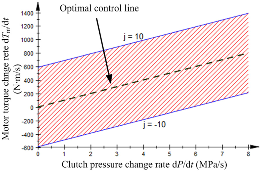
The relationship between the clutch pressure change rate and the motor torque change rate.
The shaded region in Figure 6 represents the control feasible region. As long as the change rates are controlled in this region, the vehicle jerk can satisfy the design requirement. Theoretically, the jerks on the upper and lower boundaries are ±10 m/s3 and the jerk on the optimal control line is 0.
Vehicle jerk analysis after speed synchronization
Similarly, taking derivative of equation (4) leads to the following jerk expression
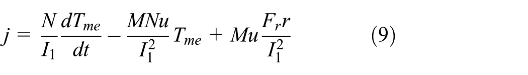
where


Substituting the basic parameters in equation (9) yields the following vehicle jerk expression, without considering the slope resistance

Equation (10) indicates that the vehicle jerk mainly depends on the change rate of the total torque (motor torque plus engine torque). The above jerk expression can be further simplified to
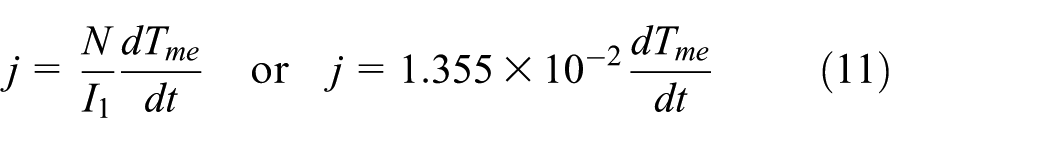
In order to meet the design requirement of

This relationship is shown in Figure 7.
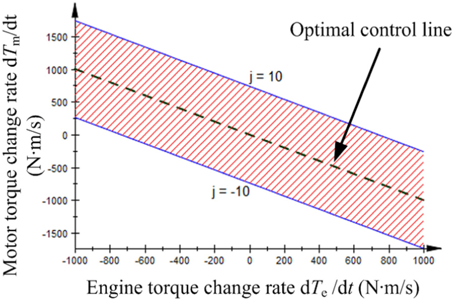
The relationship between the motor torque change rate and the engine torque change rate.
The shaded region in Figure 7 represents the control feasible region. As long as the change rates are controlled in this region, the vehicle jerk can meet the design requirement. Theoretically, the jerks on the upper and lower boundaries are ±10 m/s3 and the jerk on the optimal control line is 0.
Control strategy and simulation verification
Control strategy
In the engine cranking phase, the clutch pressure is increased and the clutch and motor are coordinated, so as to ensure that the clutch pressure change rate and the motor torque change rate are in the control feasible region.
In the synchronization phase, the change of clutch torque occurs abruptly, and this sudden change, if improperly managed, can become very large and result in a remarkable jerk. To avoid this problem, we propose that when the speed difference is less than a certain amount Δn0, the engine torque is tuned to zero and then the clutch torque is adjusted to follow equation (13) by controlling the clutch pressure

with

where Tc_Δn and Te_Δn are the clutch torque and engine torque at the moment when the speed difference is Δn.
Figure 8 illustrates the torque change routes with and without pressure control.

Speed synchronization phase control strategy.
Theoretically, when all components are controlled accurately, the effect of ΔTc can be ignored.
In the after synchronization phase, the engine torque change rate cannot be accurately controlled. Thus, the engine torque changing slope is restricted by limiting the throttle changing slope8,9 and then the engine and motor are coordinated to ensure that the engine torque change rate and the motor torque change rate are in the control feasible region.
Control flow
Based on the characteristics of the single-motor parallel HEV and the control feasible regions we have obtained, a set of control flow is established, as shown in Figure 9.
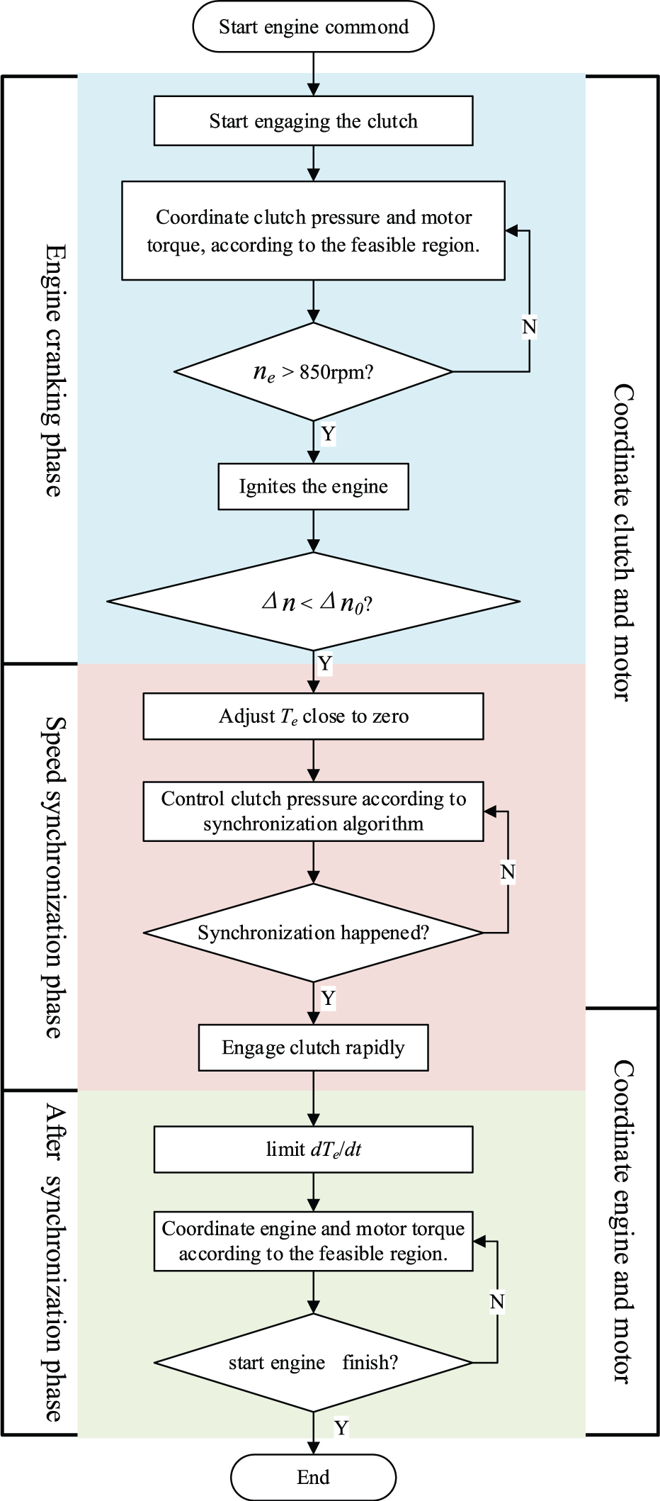
The control flow of engine starting in-motion for HEV.
Simulation and experimentation
Simulation
In the simulation studies, different vehicle speeds and continuously variable transmission (CVT) ratios are employed. Figure 10(b) shows the simulation results of engine starting in-motion when the cruise speed is 20 km/h and CVT ratio is 2.4.
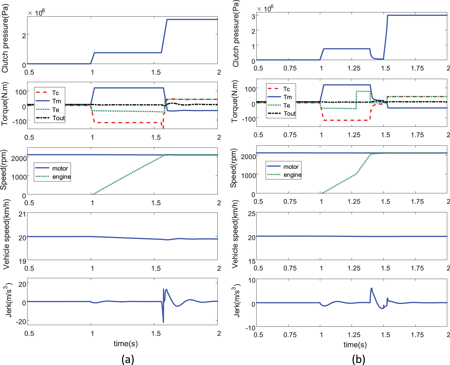
Comparison of the simulation results: (a) simulation results of the conventional strategy and (b) simulation results of the proposed strategy.
In Figure 10, the parameters Tc, Tm, Te, and Tout represent the clutch torque, the motor torque, the engine torque, and the final output torque after motor, respectively.
Figure 10(a) shows the simulation results resulting from the conventional control strategy. As can be seen, the vehicle jerk is about 22 m/s3 and the engine, motor, and clutch pressure need to be properly controlled. At the synchronization moment, the dynamic friction which depends on the clutch pressure becomes static friction suddenly, and the clutch torque is reduced as the part of torque for accelerating the engine and suddenly disappears. Note that the motor cannot coordinate timely and as a result gives rise to an inevitable shock.
Figure 10(b) demonstrates the simulation results resulting from the proposed strategy. The engine starting process starts at 1 s. The clutch pressure is increased gradually and then the engine starts rotating and the engine is ignited when its speed exceeds 850 r/min, after which the engine speed increases more quickly. When the speed difference between the engine and motor is less than Δn0 (200 r/min in Figure 10(b)), the powertrain enters the speed synchronization phase (at 1.4 s). The engine torque is tuned to zero, and the clutch pressure is decreased and then held again. Note that the clutch pressure cannot be too small to stop the synchronization from happening. Before speed synchronization starts, the clutch pressure change rate and the motor torque change rate are coordinated according to the control feasible region.
The engine speed and motor speed achieve synchronization at 1.55 s, at which moment the dynamic friction that depends on the clutch pressure becomes static friction. The clutch pressure rises steeply after speed synchronization until it exceeds 2 MPa, after which the powertrain enters the after synchronization phase.
In the after synchronization phase, the throttle change rate is limited. The motor torque is used to compensate for the engine torque, and the engine torque change rate and the motor torque change rate are coordinated according to the control feasible region.
In the whole simulation process, the maximum vehicle jerk is 6.2 m/s3, which satisfies the requirement and is significantly reduced compared to that resulting from the conventional strategy.
Experimental verification
Based on the simulation studies, a test bench (shown in Figure 11) is built to further validate the control strategy. The experimental results are plotted in Figure 12.
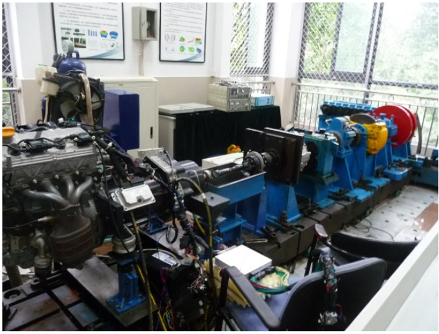
The HEV test bench for engine starting in-motion.
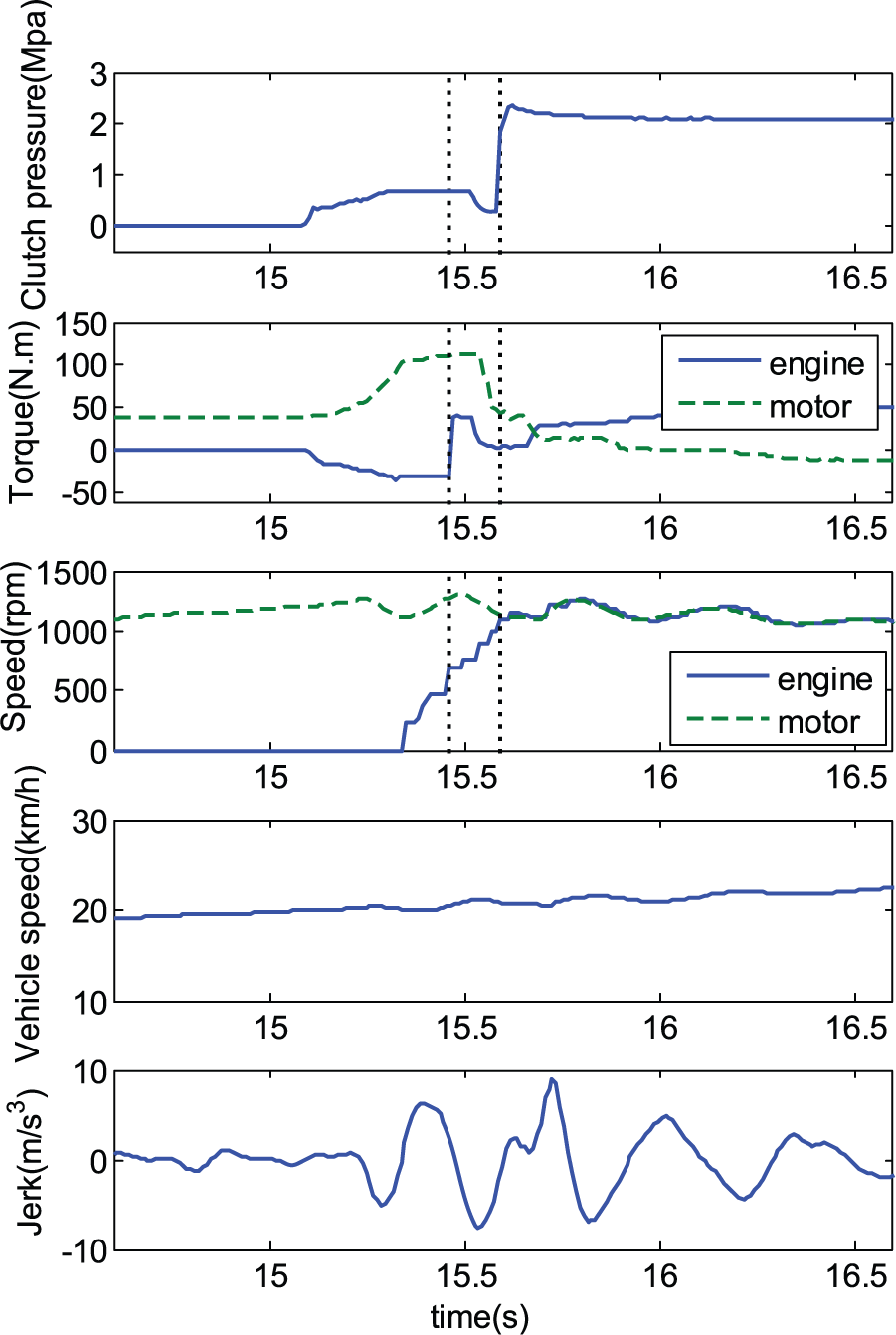
Test results for engine starting in-motion.
As shown in the test results, the “start engine” command is sent at 15.1 s. The clutch pressure immediately rises up, but it is unstable at the beginning due to the effect of the resistance resulting from the clutch disk contact. After 0.25 s, the engine starts being rotated by the motor, and the engine is ignited when its speed exceeds 850 r/min at 15.45 s. As soon as the speed difference between the engine and motor becomes less than a certain value (namely 200 r/min), the process enters the speed synchronization phase. Then, the engine torque is tuned to zero, and the clutch pressure is adjusted according to the proposed method. Speed synchronization is achieved at 15.6 s, after which the clutch pressure is quickly increased to ensure complete clutch engagement. Since then, the engine starts driving the vehicle and its torque change rate is limited. Meanwhile, the engine torque fluctuation is compensated for by the motor.
The second sub-figure in Figure 12 shows that the engine ignition shock is not transmitted to the vehicle body, and the motor works correctly to ensure stable torque output. From the third and fourth sub-figures we see that the motor speed and vehicle speed present some fluctuations during the engine starting process. This is because the accurate values of clutch torque and engine torque cannot be obtained, which makes the motor compensation torque deviate from the optimal value.
In the whole process of engine starting in-motion, we can see that the maximum vehicle jerk is about 8.9 m/s3, which well satisfies the design requirement. The proposed control strategy can smoothly start the engine in-motion, thereby improving the ride performance and driving comfort.
Conclusion
The core problem of engine starting in-motion process is the torque coordinated control which is a critical task for HEVs drivability. To tackle this problem, a control strategy for every phase of the engine starting in-motion process based on jerk analysis is proposed in this article. The effectiveness of this control strategy is validated by simulation studies and experiments. Both simulation and experimental results show that the vehicle jerk during the engine starting in-motion process is reduced significantly by means of the coordinate control strategy proposed in this article. This strategy proves effective in improving the vehicle ride performance and driving comfort.
Footnotes
Academic Editor: Haiping Du
Declaration of conflicting interests
The author(s) declared no potential conflicts of interest with respect to the research, authorship, and/or publication of this article.
Funding
The author(s) disclosed receipt of the following financial support for the research, authorship, and/or publication of this article: This work was supported by the National Natural Science Foundation of China (Grant No. 51675062).