
Abstract
The floating raft active vibration isolation system itself is a complex system with high nonlinearity, strong coupling, and multi-source excitations, so it is difficult to build a mathematical model and control the system. As an intelligent control method, the fuzzy control algorithm can provide an intelligent path for the active control of the complex floating raft system. In this article, the system identification method is adopted to establish the discrete transfer function mathematical models for the floating raft active vibration isolation system. And then for the purpose of simulation and experimental study, the fuzzy controller is designed based on dual inputs of the acceleration and its variation and single output of control voltage. Since the control effect cannot be optimized due to the fact that the quantization factors and scale factors are usually gained by trial and error method and the control rules are designed by expert experience, the quantization, scale factors, and control rules are simultaneously optimized by adopting the genetic algorithm in which hybrid coding is conducted for both real numbers and integers. The simulation and experimental results show that the fuzzy controller based on genetic algorithm is superior to the conventional fuzzy controller on vibration suppression effect.
Keywords
Introduction
Since naval vessels are important defense force, it is necessary to improve their stealth performance to enhance the combat capability. Applying the floating raft active vibration isolation technology to the warships can not only reduce the damages on the hull structure caused by the mechanical vibration force but also improve the working environment of the crew. Besides, it can reduce noise and sound intensity changes so as to avoid being detected, improving the stealth combat capability of warships.
As an effective way to control warships’ mechanical noise, the floating raft active vibration isolation technology has been studied for decades, and it has been used in warship stealth technology. EP Darbyshire and CJ Kerry 1 added 32 three-way electromagnetic actuators and more than 500 sensors on a floating raft active vibration isolation system to collect the information about displacements, accelerations, and magnetic flux, which are processed by the high-performance signal processor DSP (digital signal processor) to solve the operation efficiency problem for large floating raft active control system and reduce vibration and noise to a certain extent. The fiber distribution network technology was adopted to monitor the main noise signals caused by the main and auxiliary machinery systems on American Trident 688 and Seawolf-class submarines, and effective active noise control was implemented. 2 Winberg et al. 3 designed a double-layer vibration isolation system to suppress the vibrations generated by the operation of the Collins-class submarine diesel engine, and the active control experiment was carried out using the FXLMS (filtered-x least mean square) algorithm, which could effectively suppress the 1-, 1.5-, and 2-order frequency components. X Li et al. 4 took the motion minimization of the intermediate raft on double vibration isolation platform as control objective, and using kinetic control and modal control, good vibration isolation effect in simulation and experiment was achieved. S Daley et al. 5 applied the “smart spring” composed of an electromagnetic actuator and spring elements to the floating raft vibration isolation to eliminate the detects that the passive support could not be in the ideal continuous state, and it was difficult to accurately determine stiffness, and the overall vibration isolation performance of the ship was improved. M Kauba et al. 6 adopted the multiple-input multiple-output (MIMO) FXLMS algorithm to reduce the vibration of submarine power machinery, and the corresponding simulation analysis was conducted in the rapid control of the prototype system. In addition, the active vibration control experiments were tested on the actual ship. J Orivuori et al. 7 proposed an active vibration isolation method for frequency varying disturbs generated by diesel engine mounted on raft, and a nonlinear adaptive frequency tracking algorithm was used to control the strong coupling and high background noise in MIMO system. S Daley and I Zazas 8 used the harmonic control method based on recursive least-square (RLS) algorithm to suppress the periodic perturbation, and it was also proved that the control performance could be expressed by the feedback controller and such an expression could be used to describe the adaptive feedforward control system’s stability, convergence speed, and robustness. Y Chen 9 used the neural network to identify and control the floating raft vibration isolation system; LK Jing et al. 10 utilized the adaptive feedforward control based on FXLMS algorithm to reduce the low-frequency line spectrum vibration for a floating raft vibration isolation system with dynamic vibration absorbers. TJ Yang et al. 11 designed a floating raft active vibration isolation system whose floating raft was attached to a hold structure supported by 26 air springs, and relevant adaptive control experiments were carried out. H Chen et al. 12 studied the adaptive feedforward control based on FXLMS algorithm and its improved algorithm for the floating raft vibration control system. PJ Zhang et al. 13 applied the multi-channel decoupling control method based on FXLMS algorithm to the active and passive hybrid vibration isolation system of magnetic levitation and air springs. They also carried out two-input and two-output active vibration control experiments; Z Zhang et al. 14 proposed the FXLMS algorithm with output anti-saturation approach, which was used to solve multi-channel control problem. Actually there are few public reports since the floating raft active vibration isolation system involves the confidentiality issue for military technology. Common reports and studies just focus on the dynamic modeling and analysis of dynamic characteristics in the initial stage of the study. Until now, researches in the field of active floating raft vibration isolation system are confined to theoretical and experimental level. Certain foundations have been established in theoretical study on floating raft active vibration isolation technology, but few practical applications have been made, and most control strategies focus on adaptive feedforward control rather than feedback control. The reference signals of the multi-source excitation floating raft system have complex frequency components and fluctuations, so it is difficult for the adaptive feedforward control method to achieve significant control effect.
With the development of warships, the structure and excitation of the internal mechanical power equipment are increasingly complex. In addition, within the limited interior space and load capacity, lots of equipment mount together rigidly or elastically, which forms a complex multi-source excitation vibration isolation system; the floating raft cannot be regarded as a rigid body because of its small weight, large size, and small relative stiffness; the coupling is strong among units, floating raft, actuators, and isolators. It can be seen that the floating raft active isolation system is a complex dynamic system, and its multi-excitation, nonlinearity, and strong coupling features make it hard to model and control. Thus, a control strategy which is applicable for nonlinear system and does not depend on the exact model of the controlled subject may offer an effective control method to the floating raft active vibration isolation system. The fuzzy control, based on fuzzy mathematics theory and simulating the process of human approximate reasoning and comprehensive decision, is an important branch of intelligent control. Thus, it can provide an intelligent method for controlling the complex systems. In terms of the application of fuzzy control in vehicle suspension,15,16 civil engineering structures,17,18 flexible structures, 19 and other areas of engineering vibration and noise reduction, great achievements have been made. A Shehata et al. 15 designed the fuzzy controllers for the vehicle suspension system, which improved the performance of the suspension system by changing the number and arrangement of rules and the scope of the domain, that is, the different types of fuzzy rules and membership functions were studied how to influence the performance of the active suspension system; X Dong et al. 16 proposed an adaptive fuzzy logic control (FLC) based on a hybrid Taguchi genetic algorithm (GA) to overcome the limitations of conventional FLC strategies so as to suppress the vibration of the magneto-rheological (MR) suspension better; MR Elhami et al. 17 used fuzzy control theory to determine appropriate command voltage applied to MR damper and GA to optimize the fuzzy rules, and experimental results showed that the amplitude of vibrations decreased significantly in the presence of optimized fuzzy rules through GA; ME Uz and MNS Hadi 18 proposed an optimal design strategy based on GAs for nonlinear hysteretic control devices, and the results obtained by fuzzy controller were compared with that gained from linear quadratic regulator (LQR) and H2/LQR; AHN Shirazi et al. 19 investigated the active vibration control of a simply supported rectangular plate made from functionally graded materials (FGM) with FLC and compared the results obtained with the application of proportional–integral–derivative (PID) control, and results showed that FLC had better performance to dampen the vibration of the smart plate compared to PID control. Fuzzy control in these areas mainly focuses on single-input single-output control and rarely involves MIMO control. Moreover, the optimization of fuzzy control by GA is limited to the optimization of single parameter, such as optimizing factors only, membership functions only, control rules only, and no mixed optimization between or among them. Referring to the research achievements in above areas and the similar nonlinear characteristics, applying the fuzzy controllers with combinatorial optimization by GA to the two-input two-output floating raft active vibration isolation system has practical significance for warships’ vibration and noise reduction.
In this article, the mathematical model of the floating raft active vibration isolation system is gained by system identification method, and the dual-input single-output Mamdani-type fuzzy controllers are designed. In addition, dual-frequency interference dual-channel control simulations are conducted. Quantization factors, scale factors, and control rules of the fuzzy controllers are simultaneously optimized by means of adopting GA. In the end, experiments are conducted to verify the control effect of the optimized fuzzy controller.
Mathematical model of the floating raft active vibration isolation system
Test rig of the floating raft active vibration isolation system
Figure 1 shows the mechanical device section of the floating raft active isolation system, which is mainly composed of four motors, 1-1, 1-2, 1-3, and 1-4, four motor supporting plates, 2-1, 2-2, 2-3, and 2-4, four electromagnetic actuators, 3-1, 3-2, 3-3, and 3-4, four lower layer rubber isolators, 4-1, 4-2, 4-3, and 4-4, upper isolators, raft 4 and the base 5, and so on. The raft and the base are connected by lower layer rubber isolators, and the four electromagnetic actuators are rigidly connected with the base. 6-1, 6-2, 6-3, 6-4, and 6-5 represent five acceleration sensors, whose measurement values can be used as feedback error signals or used to evaluate the effect of vibration isolation.
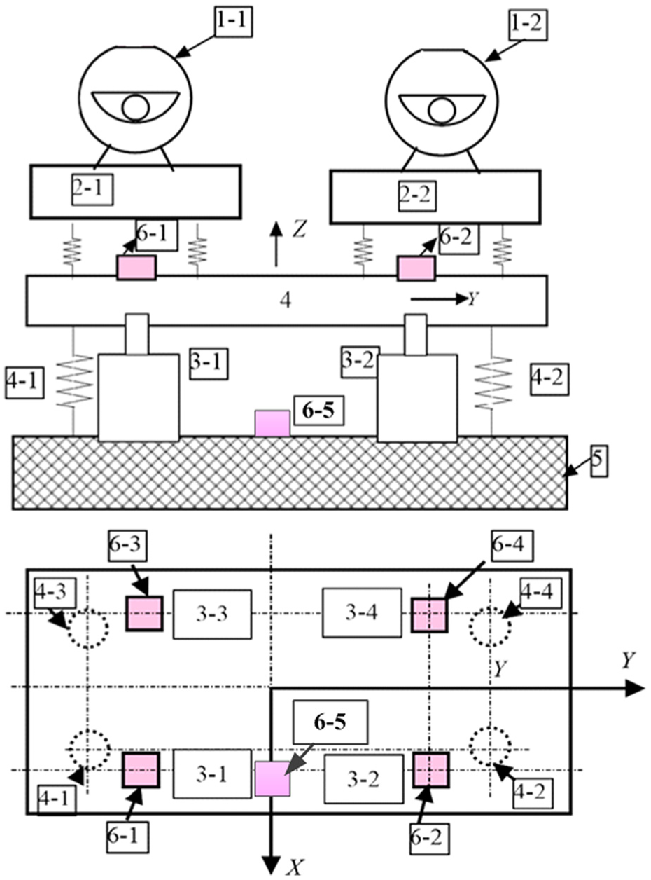
Test rig of the floating raft active vibration isolation system.
Model identification for the floating raft active vibration isolation system
The floating raft active vibration isolation system is a nonlinear and strong coupling system. As some objective factors like its structure and parameters are not clear, the usage of mechanism analysis modeling is unsuitable. According to black-box system identification method, the input excitation data and output response data of control channel can be used to establish mathematical models. System identification can be divided into time-domain identification and frequency-domain identification according to the type of input and output data and can be divided into least-square method, minimum mean square estimation, and gradient estimation algorithm according to calculation principle. Besides, it can also be divided into non-parametric model and parametric model according to the model expression. In this article, the least-square method in frequency domain is adopted to establish discrete transfer function mathematical model for the floating raft active vibration isolation system, choosing the ARX (AutoRegressiveeXogenous) as fitting model of the controlled object’s discrete transfer function. Mathematical expression of the ARX is as follows

where

where
Figure 2 shows the schematic of model identification for the floating raft vibration isolation system, and the system identification process is mainly divided into three steps:
Collect input and output data of the system. Input signal is the white noise signal with the frequency range of 0–80 Hz and the effective voltage of 1.5 V. The white noise signal generated from signal source is filtered through a low-pass filter and then applied to the electromagnetic actuator using a power amplifier. After being conditioned, amplified, and filtered, the sensor signal is transmitted to the data acquisition instrument. The acquired input signal is the filtered white noise signal. Sampling time is 10.9 s, and sampling frequency is 750 Hz.
Use input and output data to identify the model. The first step is to process the data by selecting the response data within the frequency range of 3–80 Hz. The data whose coherency is less than 0.95 should be filtered out. MATLAB system identification toolbox is used to import the processed frequency response data and choose the type of model and order number, after which appropriate settings are made to obtain identification model.
Test the fitness and stability of identification model. Compare the frequency response of identification model with experimental model and observe its fitness in the main working frequency. Then, identification models should be selected based on the principles of high fitness and low order number to judge the stability according to pole-zero diagram.

Schematic of model identification for the floating raft vibration isolation system.
In this article, the discrete transfer functions G11 and G12 between 1# amplifier and sensor 6-1, 6-2, as well as G21, G22 between 2# amplifier and sensor 6-1, 6-2, are identified. The mathematical expressions of discrete transfer function are as follows
where G11, G12, G21, and G22 discrete transfer functions can be expressed as the discrete transfer function matrix GM
where

As is depicted in Figure 3, model carve for identification model and experimental model is well fitted in the whole frequency domain, especially in the working frequency. The carve fitness of G11 is 90.76% and the order number is 12; the carve fitness of G12 is 94.09% and the order number is 12; the carve fitness of G21 is 92.56% and the order number is 12; the carve fitness of G22 is 93.76% and the order number is 12. Pole-zero map of identification model is shown in Figure 4. The poles of the four discrete transfer function models are within the unit circle, and this proves the stability of the model.
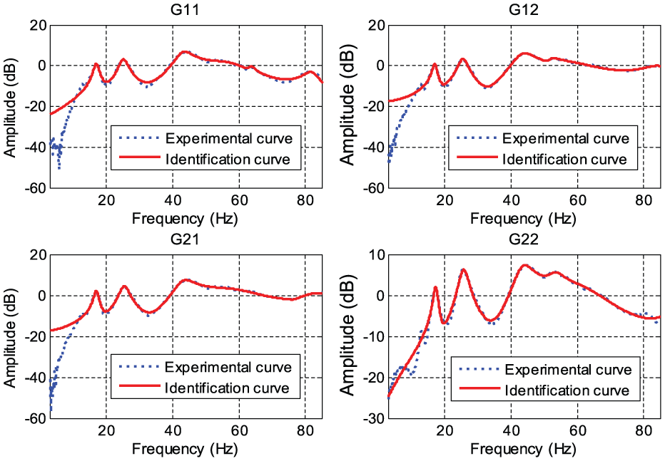
Comparison chart of frequency response for identification model and experimental model.

Pole-zero map of identification model.
Fuzzy control based on GA
Design of fuzzy controller
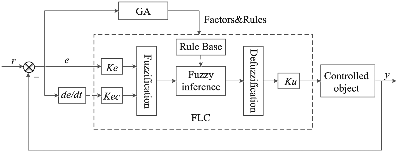
The input variables of two-dimensional fuzzy controller have two components, and error and error ratio (variation) are always chosen for reflecting the dynamic characteristics of output variables of a controlled object. Structural model of Mamdani-type with dual-input and single-out is adopted in this article, and the inputs are acceleration and its variation and the output is control voltage, which are represented by letter E, EC, and U, respectively. The fuzzy domain of E, EC, and U is set to [−3, 3], and PB (positive big), PS (positive small), ZO (zero), NS (negative small), and NB (negative big) are adopted to describe their fuzzy state. Taking Ke and Kec as the quantitative factors of acceleration and acceleration variation and Ku as the scale factor of output voltage, the physical domain of acceleration, acceleration variation, and output voltage are (−3Ke, 3Ke), (−3Kec, 3Kec), and (−3Ku, 3Ku), respectively. Centroid method is adopted for defuzzification. Triangles are selected to be the type of membership function of the fuzzy input and output variables, which are shown in Figure 5.

Membership function curve of E, EC, and U.
Fuzzy rule is the core of fuzzy controller, and it shows the relationship between fuzzy input and output by means of language. The floating raft vibration isolation system aims at reducing the vibration transmitted to the basis, and the acceleration values are used to measure the vibration size in this article. Therefore, based on the four situations of the acceleration changes, the fuzzy control rules are established:
If acceleration value is positive, and the acceleration variation increases, then larger negative force is needed;
If acceleration value is positive, and the acceleration variation decreases, then smaller negative force is needed;
If acceleration value is negative, and the acceleration variation increases, then smaller positive force is needed;
If acceleration value is negative, and the acceleration variation decreases, then larger positive force is needed.
Based on above four cases, 25 rules of the fuzzy controller are established according to the conditional statement of If “<E&EC>, Then<U>,” as shown in Table 1.
Control rules table of conventional fuzzy controller.

PB: positive big; PS: positive small; ZO: zero; NS: negative small; NB: negative big.
Quantization, scale factors, and control rules optimized by GA
The role of the quantization factors and scaling factors is to complete the conversion of fuzzy domain and physical domain, that is, the input and output variables are enlarged or reduced by a certain scale. Such conversion plays a regulatory role in the control system. When the quantization factors and scale factors are too large or too small, the response speed, overshoot, transition time, and steady-state accuracy of the system are affected. In the process of setting up the quantization factors and scaling factors for the control system, the theoretical values converted from the ratio of fuzzy domain and physical domain cannot lead to good control effect. What’s more, obtaining quantization factors and scaling factors by means of trial and error method is time-consuming, and the combination of values obtained from such method cannot guarantee optimization of the system.
The selection of control rules and membership functions for fuzzy controller depends on expertise experience, which means it has strong subjectivity. Especially, as the control rules are the core of the fuzzy controller, fuzzy controller’s performance depends largely on the selection of control rules. Once the control rules are set, it is difficult to change. When the controlled process goes beyond the range of experience under the influence of disturbances, it is difficult for fuzzy control to adapt to the control process changes and produce the ideal control effect. In this case, the control rules, the membership functions, and other parameters need to have possessed self-tuning capabilities. As a global optimization algorithm, GA can reduce the requirement of human heuristic knowledge and can well meet the requirements of fuzzy control.
In this article, the quantization factors, scale factors, and control rules are simultaneously optimized by adopting GA. The fuzzy controller based on GA consists of two major parts; the first one is fuzzy controller whose parameters Ke, Kec, Ku, and control rules change dynamically, and the fuzzy controller directly controls the controlled object; the second is the optimization procedure of GA, which obtains the parameters according to the operating status of the floating raft active vibration isolation system. Then, the parameters are assigned to the fuzzy controller. The schematic diagram of fuzzy controller based on GA is shown in Figure 6.
Schematic diagram of fuzzy controller based on genetic algorithm.
When the GA is used to optimize the fuzzy controller, the quantization factors, scale factors, and control rules need to be encoded to determine the fitness function. Selection, crossover, and mutation operations should be designed for chromosomes. When specified number of generations or other termination conditions is reached, the optimization process can be ended. Upon reaching the termination condition, the population of best fitness value is gained, in which the best individual is the optimal solution of quantization, scale factors, and control rules for fuzzy controller:
Encoding. The priority for GA to optimize the quantization, scale factors, and control rules is encoding. The common encoding methods are binary encoding, gray encoding, real coding, integer coding, and so on. Real encoding with clear physical meaning can improve the accuracy of the solution and calculation speed; integer encoding with good global convergence performance is suitable for variable discrete issues. In this article, the quantization factors and scale factors are encoded by real coding, and the control rules are encoded by integer encoding. The input and output linguistic variables {NB, NS, ZO, PS, PB} are sequentially encoded as {1, 2, 3, 4, 5}, so the control rules can be parameterized, while the quantization factors and scale factors are in certain changes in the real number range. Therefore, the structure of individual chromosome made up by the quantization, scale factors, and control rules is formed as shown in Figure 7.
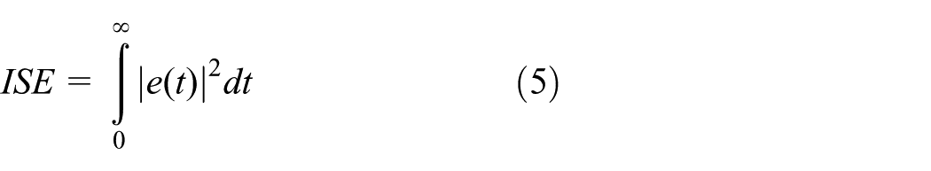
Designing of fitness function. Fitness function is actually equivalent to the objective function of optimization process. The fitness function is used to evaluate the merit of individuals in a population, and its selection affects the convergence speed and optimization results of GA. Generally, individuals with high fitness value are likely to survive. Crossover operation and mutation operation should be carried out, respectively, for individuals whose fitness is higher than the average value of the population and individuals whose fitness is lower than the average value of the population. By doing so, the evolution of the population continues. In this article, the value of vibration acceleration is regarded as evaluation criteria, and the purpose is to reduce the vibration acceleration. In order to increase the response speed and reduce the dynamic bias, the ISE (integral square error) is chosen to design fitness function, that is
Selection. In this article, the best reservation method is chosen as selection operator. First, the selection process is performed in the roulette way and then the individual of highest fitness value in the contemporary population is completely copied to the next generation in order to ensure that the result gained in the end of GA is the best individual in successive dynasties.
Crossover. Two different crossover operators are introduced to optimize quantization, scale factors, and control rules. The factor portion of the individual chromosomes uses arithmetic crossover method, that is, linear combination calculation is carried on for each pair of parent individuals to form a new pair of offspring, which is suitable for real encoding. For example, arithmetic crossover is conducted for two parent individuals
wherein
Mutation. Uniform mutation is adopted in this step. Use the random numbers uniformly distributed in a certain range consistent with the factors portion and the control rules portion to replace the original chromosomal gene value in the corresponding position with a certain probability. For example, the mutation random number of factors portion can be assigned to the real number [0 50], and the mutation random number of control rules portion can be assigned to the integer [0 5].

Structure of chromosome.
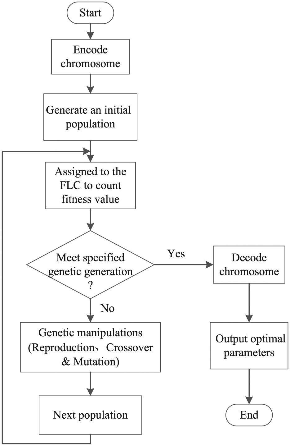
The specific process of GA optimizing fuzzy controller is shown in Figure 8. And the process can be divided into six steps.
Determine the value range of the parameterized quantization, scale factors, and control rules;
Determine crossover probability Pc, mutation probability Pm, population size N, the maximum evolution generation G, and so on;
Encode to generate initial population P(t), t = 0;
Assign the fuzzy controller and calculate the fitness value of individuals based on system status;
Generate a new generation of population P(t + 1) through selection, crossover, and mutation genetic manipulations;
Repeat step (d) and step (e) for the new generation of population until the specified evolution generation is reached. Then, end the algorithm.
Process of genetic algorithm optimizing fuzzy controller.
Simulation of fuzzy control for the floating raft active vibration isolation system
Generally, there are some multiple r machinery running simultaneously on the ship floating raft system. In order to meet the actual situation, the 25- and 45-Hz dual-frequency sinusoidal signals are employed to simulate the situation created by multiple devices. In addition, the floating raft system in the run-time will be disturbed, so in the simulation, white noise signals are adopted to represent random signal interferences. The discrete transfer function matrix GM is used to conduct MATLAB/Simulink dual-channel fuzzy control simulation. The Simulink simulation diagram is shown in Figure 9.
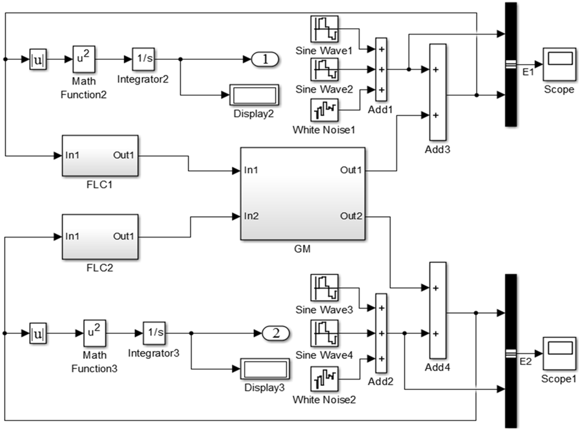
Diagram of dual-channel fuzzy control simulation.
Wherein FLC1 and FLC2 are two conventional fuzzy controllers, and E1 and E2 represent acceleration error signals on dual-channel control points. After much trial and error, the quantization factors and scaling factor can be assigned to [5.2 10.3 −0.26 45.3 30.7 0.08]. The simulation time is 3 s, and the sampling time is 1/750 s. The simulation results are shown in Figures 10 and 11.
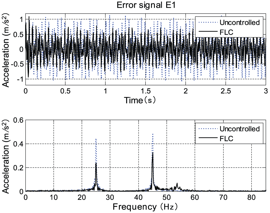
Simulation results of signal E1 before and after the conventional fuzzy control.
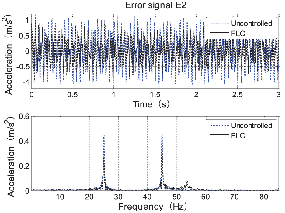
Simulation results of signal E2 before and after the conventional fuzzy control.
In both Figures 10 and 11, the first diagram is the time-domain diagram of error signal. The vertical axis represents the response magnitude of the error signal, and the horizontal axis represents time. The dotted line represents the response curve of the error signal before being controlled, and the solid line is the response curve of the error signal after conventional fuzzy control is carried out. The second diagram is the frequency-domain diagram of error signal. The vertical axis represents the amplitude of error signal, and the horizontal axis represents time. Similarly, the dotted line is the response curve of the error signal before being controlled, and the solid line is the response curve of the error signal after conventional fuzzy control is conducted.
As depicted in the time-domain diagram of Figure 10, the fluctuation amplitude of error signal E1 varies from 1.139 m/s2 before being controlled to 0.7249 m/s2 after being controlled, and the number is reduced by nearly 2/5. As depicted in the frequency-domain diagram of Figure 10, the response amplitude of error signal E1 at 25 Hz decreases from 0.4423 m/s2 before being controlled to 0.2357 m/s2 after being control, which is a decrease of 46.71%. And the response amplitude of error signal E1 at 45 Hz decreases from 0.4862 m/s2 before being controlled to 0.3256 m/s2 after being controlled, which is a decrease of 33.03%.
Similarly, as shown in the time-domain diagram of Figure 11, the fluctuation amplitude of error signal E2 declines almost 3/10 before and after FLCs; as shown in the frequency-domain diagram of Figure 11, the response amplitude of error signal E2 at 25 Hz decreases about 41.01% and decreases about 27.50% at 45 Hz before and after FLCs.
Simulation results show that the conventional fuzzy controllers have certain inhibitory effects on vibration interference signals with random signal interferences at the frequency of 25 and 45 Hz, but the inhibitory effect is not very satisfactory. This is because the controllers are not optimal fuzzy controllers. The quantization factors and scale factors of fuzzy controllers are selected by the trial and error, and its control rules completely rely on expert experience, in which case there is a lot of subjectivity. It is difficult to obtain a good vibration suppression effect, and for this reason, the GA is adopted to optimize the quantization factors, scale factors, and control rules simultaneously for the conventional controllers, FLC1 and FLC2, to obtain better control effect. Set the initial population, evolution generation, crossover probability, and mutation probability, respectively, to 150, 120, 0.8, and 0.05. The optimization process is shown in Figure 12. Since the FLC is reconstructed at every simulation run, it may be much slower than a fixed FLC structure. When the termination condition of 120 generations is reached, the population still has diversity, and the optimization has not been restrained, so the optimal value is obtained from the individual of 120 generations. Therefore, the optimal parameters for FLC1 are as follows: [41.4 29.4 0.15 1 3 2 3 4 2 2 4 2 4 2 1 4 2 4 3 2 3 3 4 2 3 4 4 5], and the optimal parameters for FLC2 are as follows: [37.1 32.3 0.06 4 3 4 3 4 3 4 3 3 1 2 2 3 2 4 3 2 2 2 2 2 3 3 4 3].

Iterative process of genetic algorithm optimizing factors and rules.
The optimized quantization, scale factors, and control rules parameters are used to redesign the fuzzy controller FLC1 and FLC2, and simulation results are shown in Figures 13 and 14.

Simulation results of signal E1 before and after the fuzzy control based on genetic algorithm.

Simulation results of signal E2 before and after the fuzzy control based on genetic algorithm.
Analogously, as can be seen in Figures 13 and 14, the fluctuation amplitudes of error signals E1 and E2 attenuate significantly in the time domain, and the same thing happens to the response amplitudes of error signals E1 and E2 at 25 and 45 Hz in the frequency domain. Comparing the simulation results of the conventional fuzzy controllers and the fuzzy controllers based on GA, the control effect of optimized fuzzy controller is obviously improved. The drop of fluctuation amplitudes of error signals with GA-FLCs is 15% higher than FLCs, and the decrease in the response amplitudes of error signals at 25 and 45 Hz with GA-FLCs is 14% higher than FLCs.
Experimental study of fuzzy control for floating raft active vibration isolation system
The two-input two-output fuzzy control system is shown in Figure 15. The voltage signal proportional to the acceleration signal from the low-pass filter can be regarded as error signals, E1, E2, and E3, as shown in Figure 15. E1 represents the acceleration signal from the conditioning and filtered 1# acceleration signal, E2 represents the acceleration signal from the conditioning and filtered 2# acceleration signal, and E3 refers to the acceleration signal from the conditioning and filtered 3# acceleration signal. The filter output port is connected with the A/D port of CLP1103, which is the wiring panel of dSPACE1103 system. As a controller hardware, the control board, DS1103, calculates the control amount based on the designed controller. Since one of the inputs for fuzzy controller is acceleration variation, namely, the error signal variation, a Z−1 discrete segment exists in the controller. For this reason, the controller solver uses discrete, and the calculation method uses fixed-step calculation method, of which the step is 1/750. After crossing D/A converter, the control amount outputs two control signals, U1 and U2, as shown in Figure 15. The amplitudes of the two control signals are confined to ±3 V. The control signal U1 goes across 1# power amplifier and then drives l# electromagnetic actuator to output control force; the control signal U2 goes across 2# power amplifier and then drives 2# electromagnetic actuator to output control force. On the coordinative role of the two actuators, the dual-frequency interference generated by the motors can be inhibited.

Two-input two-output floating raft active vibration isolation system.
The rotational speed of the 2# vibration motor is set to 1500 r/min, and the rotational speed of the vibration motor 3# is set to 2700 r/min as shown in Figure 15. Collect vibration acceleration values of the 1# acceleration sensor and 2# acceleration sensor and use them to simulate in MATLAB/Simulink to get parameters of the fuzzy controllers FLC1 and FLC2 and then conduct two-input two-output fuzzy control experiments on the floating raft active vibration isolation system. The experimental results are shown in Figures 16–18, among which Figure 18 shows the vibration response of E3 on the foundation. The control effects of fuzzy controllers based on GA are significantly better than that of conventional controllers.
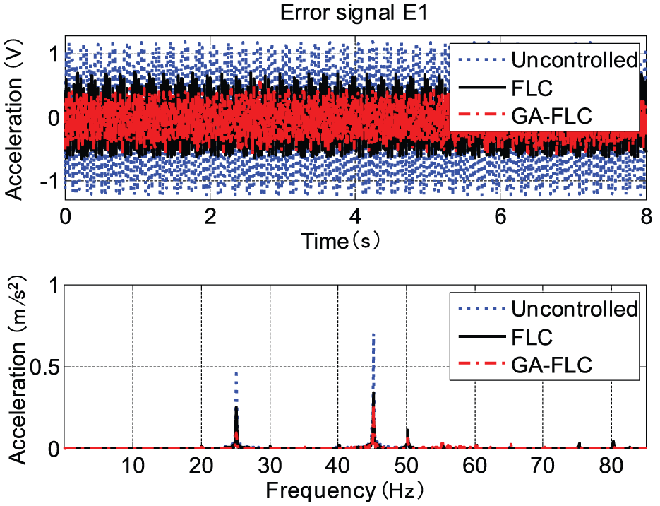
Experimental results of the error signal E1.
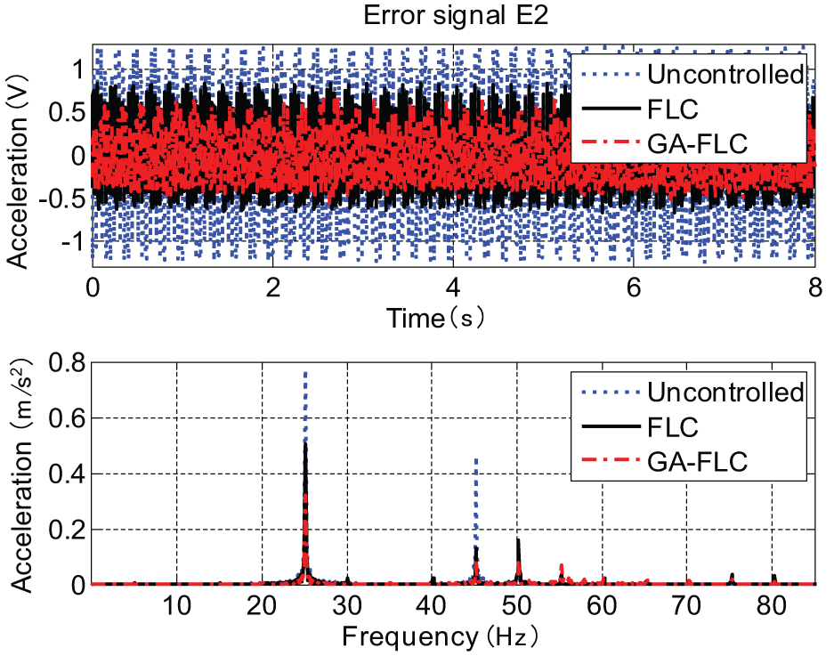
Experimental results of the error signal E2.

Experimental results of the error signal E3.
As shown in Figure 16, when the fuzzy controllers based on GA are used, the response amplitude of error signal E1 at 25 Hz decreases from 0.4782 m/s2 before being controlled to 0.09526 m/s2 after being controlled, and this is a decrease of 80.1%. And the response amplitude of error signal E1 at 45 Hz decreases from 0.6989 m/s2 before being controlled to 0.271 m/s2 after being controlled, and this is a decrease of 61.2%. When the conventional fuzzy controllers are used, the response amplitude of error signal E1 at 25 Hz decreases from 0.4782 m/s2 before being controlled to 0.2502 m/s2 after being controlled, and this is only a decrease of 47.7%, and the response amplitude of error signal E1 at 45 Hz decreases from 0.6989 m/s2 before being controlled to 0.3374 m/s2 after being controlled, and this is a decrease of 51.7%.
As shown in Figure 17, when the fuzzy controllers based on GA are used, the response amplitude of error signal E2 at 25 Hz decreases from 0.7726 m/s2 before being controlled to 0.3225 m/s2 after being controlled, which is a decrease of 57.0%. And the response amplitude of error signal E2 at 45 Hz decreases from 0.4624 m/s2 before being controlled to 0.088 m/s2 after being controlled, and this is a decrease of 81.0%. When the conventional fuzzy controllers are used, the response amplitude of error signal E2 at 25 Hz decreases from 0.7726 m/s2 before being controlled to 0.5044 m/s2 after being controlled, and this is only a decrease of 34.7%, and the response amplitude of error signal E2 at 45 Hz decreases from 0.4624 m/s2 before being controlled to 0.1297 m/s2 after being controlled, and this is a decrease of 72.0%.
As shown in Figure 18, after being controlled, the response amplitudes of E3 at 25 and 45 Hz are reduced. Especially when GA-FLC is being used, the amplitude decreases 73.1% at 25 Hz, which is 33.5% higher than FLC. The number decreases 40.9% at 45 Hz, which is 14.6% higher than FLC. The results show that the fuzzy controllers based on GA can effectively suppress the vibration transmitted to the foundation from the power equipment.
Conclusion
Concerning the discrete transfer function model of the floating raft isolation system obtained using system identification, its fitness can be higher than 90%. And the models are proved to describe the dynamic characteristics of the controlled object accurately.
The design method of fuzzy controller as well as the process of using the real- and integer-coded hybrid GA to optimize the quantitative factors, scale factors, and control rules simultaneously is introduced.
Conventional fuzzy controller and fuzzy controller based on GA are used to perform the numerical simulation and experiments for the floating raft active vibration isolation system. The results show that the control effects of optimized fuzzy controllers are better than that of the conventional fuzzy controllers. When the optimized fuzzy controllers are used in the experiments, the response amplitudes of the error signals E1 and E2 decrease over 57.0% at 25 Hz, and the response amplitudes of the error signals E1 and E2 decrease over 61.2% at 45 Hz. This means a good isolation effect is achieved. In addition, the error signal E3 reflects the vibration response of the foundation, and the results show that the fuzzy controller can inhibit the vibration transmitted to the foundation from the power equipment.
Footnotes
Academic Editor: Anand Thite
Declaration of conflicting interests
The author(s) declared no potential conflicts of interest with respect to the research, authorship, and/or publication of this article.
Funding
The author(s) disclosed receipt of the following financial support for the research, authorship, and/or publication of this article: This study was supported by the National Natural Science Funds of China (51205296 and 51275368).