
Abstract
To overcome the serious coupling between torque and levitation forces, increase the output torque, and improve fault tolerance performance for the bearingless brushless direct current motor, a multi-phase double-stator bearingless brushless direct current motor is designed in this article. First, basic structure and operation principle of the bearingless brushless direct current motor are analyzed in detail. The proposed motor is composed of inner and outer stator, the levitation force windings on the inner stator realize suspending function, while the torque windings on the outer stator realize the rotating function of the rotor. Second, the mathematical model of the levitation forces is deduced, which indicates that the levitation forces are independent of the torque. Finally, based on the finite element analysis method, a 20-slot/18-pole five-phase double-stator bearingless brushless direct current motor model is established. The optimizations are carried for its main parameters to minimize the cogging torque and improve the motor performance. The simulation results confirm that the proposed bearingless brushless direct current motor has the superior decoupling characteristics compared with the double-winding bearingless brushless direct current motor. Meanwhile, the motor has the higher output torque and the better fault tolerance performance. According to the simulation model, a prototype is made and measured to validate the analyses. Since there is little relationship between the torque and levitation forces, they can be designed independently and controlled with high precision easily.
Introduction
Bearingless brushless direct current (BBLDC) motors can be constructed by wounding a set of levitation windings around the stator teeth of the brushless direct current (BLDC) motor. The BBLDC motor, with all advantages of the BLDC motor and magnetic bearings, has a broad application prospects from biomedicine to aerospace since they offer several key features such as high efficiency, small volume, no friction, no wear, long life.1–3
Traditionally, the BBLDC motor with the double-winding topology is usually adapted to generate the required torque and levitation forces. In Ooshima and Rahman, 4 a 12-slot/8-pole BBLDC motor is presented, and the corresponding control strategy is proposed to realize the levitation operation. Due to the magnetic field generated by the torque and levitation force windings interact with each other, the torque and levitation forces have strong interference. In Zhu and Li, 5 an analysis method called the magnetic field equivalent current is put forward to analyze the operation principle and confirm the necessary conditions for the production of stable levitation forces. However, detailed analyses of the decoupling between the torque and levitation forces are not carried out. A 12-slot/4-pole BBLDC motor is proposed in Chen and Zhu, 6 and the mathematical model of the levitation forces is built accurately. The decoupling between the torque and levitation forces has achieved by energized asynchronization on the same teeth. Hence, the levitation forces are difficult to independent completely.
Due to the existence of strong coupling relationship between the torque and levitation forces, the double-winding bearingless motor has reached the technical bottleneck in engineering application. To overcome the shortcomings, a double-stator bearingless switched reluctance (BSR) motor/generator is proposed in Zhou and colleagues,7,8 and the levitation force and torque windings wound around the inside and outside of the stator, respectively. Comparing with the hybrid-stator BSR motor, 9 the proposed motor can effectively realize the decoupling between the torque and levitation force windings. But four power amplifiers are required to drive the levitation subsystem of the motor, and the hardware cost of the control system is increased.
Comparing with the traditional three-phase motor, multi-phase motor (phase number n > 3) realizes high power/torque density, decreases the torque ripple, and increases system reliability.10–15 In Jiang et al., 16 a five-phase bearingless permanent magnet motor is proposed to increase the system reliability, which can operate normally under fault conditions.
Based on the above theory, a novel type of five-phase double-stator BBLDC motor is presented in this article, in which levitation force windings are placed around the inner stator and torque windings are placed around the outer stator. In section “Motor topology and operating principle,” the topology and operation principle of the proposed BBLDC motor are designed and analyzed in detail. Subsequently, the mathematical model of levitation forces is deduced. In section “Optimization of the motor parameters,” optimizations of the main parameters are discussed to reduce the cogging torque and improve the motor performance by the two-dimensional (2D) finite element analysis (FEA). The electromagnetic performances and the corresponding discussion of the machine are given in section “FEA validation of the model” by comparing with the double-winding BBLDC motor. The proposed motor has superior levitation force and torque characteristics due to the self-decoupling in the structure. In section “Experimental verification,” a prototype is made and measured to validate the analyses. Finally, conclusions are drawn in section “Conclusion.”
Motor topology and operating principle
The topology of the motor
The 2D FEA motor model of the novel five-phase double-stator BBLDC motor is established, which can be shown in Figure 1(a). From inside the model to the outside, it consists of an inner stator, inner permanent magnets, an inner rotor, a magnetic separation aluminum ring and an outer rotor, outer permanent magnets, and an outer stator. The levitation subsystem is constituted with the inner stator, levitation force windings, inner permanent magnets, and inner rotor, and the torque subsystem is composed of the outer stator, torque windings, outer permanent magnets, and outer rotor.

Structure diagram and flux distribution of five-phase double-stator BBLDC motor: (a) structure diagram and (b) flux distribution.
Compared with the integer-slot concentrated-winding (ISCW) topology, the multi-phase fractional-slot concentrated-winding (FSCW) motor has higher torque density and smaller torque ripple.17,18 Thus, a 20-slot/18-pole single-layer FSCW topology is adopted in the torque subsystem. Torque windings of each phase are separated by a fault tolerant tooth, and a 144-degree square wave can be achieved by regulating widths of armature teeth and fault tolerant teeth. 19 The fault tolerant teeth without windings can be utilized as a magnetic flux loop and can isolate heat and electricity between each phase, so each phase can be regarded as an independent part. When a single-phase fault occurs, the phase windings will be cut off, and the motor can normally run by compensating the other phase current. In the levitation subsystem, the 6-slot/2-pole double-layer ISCW is adopted, and the 2-pole pair inner permanent magnets are used to provide bias magnetic field. When the current is added to the levitation force windings, the balance of original bias magnetic field will be broken. Thus, the levitation forces are generated based on Maxwell’s stress tensor method. Figure 1(b) shows the magnetic flux distributions which generated by the torque and levitation force winding current. The magnetic flux path between the torque and levitation subsystem is independent since the inner and outer rotor separated by the magnetic separation aluminum ring. Hence, the characteristics of self-decoupling is realized in the two subsystems.
The principle of torque generation
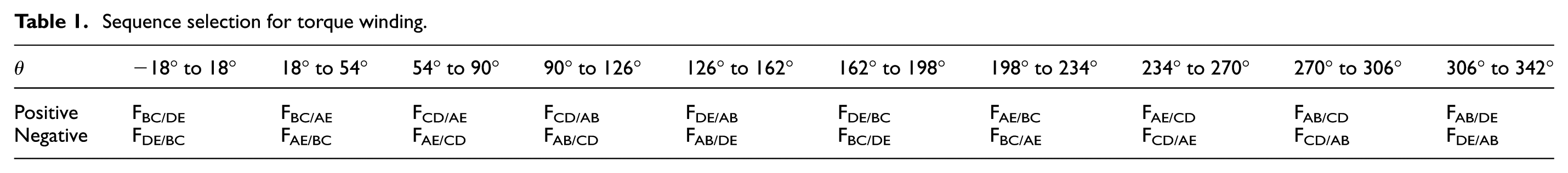
The torque windings on the outer stator are energized in sequence through a combination of microcontroller and Hall Effect sensors placed on the stator and fast switching inverter. 20 It can be regarded as an ordinary five-phase BLDC motor due to the independence of the torque and levitation subsystem. By choosing an appropriate switching sequence, a rotating magnetic field which moves the rotor along with it is developed. The excitation sequence of the windings determines the rotation direction and speed of the motor. Assuming that the anticlockwise direction is the positive direction, to orientate conveniently, take the A phase of the torque and levitation force winding on a straight line. As shown in Figure 1(a), the torque windings are distributed anticlockwise on the armature teeth, and the phase sequence arrangement is (A+) → (D−) → (B+) → (E) → (C+) → (A) → (D+) → (B) → (E+) → (C−). The five-phase magnetic motive force (MMF), separated in space by 72° electrical degree, is required to set up a revolving flux around the stator as shown in Figure 2(a). At any instant, four out of five phases will be conducting to maintain an uninterrupted uniform flux. The symbol FAB/CD represents the synthetic MMF which energized by A, B, C, and D phase current simultaneously, with A, B phase current inflow while C, D phase current outflow. To produce the maximum torque, the armature magnetic field should be kept perpendicular to the rotor magnetic field. For example, when the rotor electrical angle is between −18° and 18°, it could choose the synthetic MMF FBC/DE rotating in the positive direction or choose FDE/BC rotating in the negative direction. According to this regulation, 10 states for the torque winding sequence are shown in Table 1 in two rotation directions.

Torque and levitation force generation: (a) resultant magnetic motive force of single phase and four phases and (b) operation principle of levitation force.
Sequence selection for torque winding.
The principle of levitation force generation
There are two kinds of magnetic fields in the levitation subsystem, one is generated by the 4-pole inner permanent magnets and the other is produced by the 2-pole levitation force windings. The resultant air gap magnetic field is unbalanced through the superposition of two air gap magnetic fields. Hence, the levitation force will be generated, as shown in Figure 2(b).
Assume that the levitation force windings are excited by the sinusoidal current as follows

where ia, ib, and ic are the current of phase A, B, and C, respectively. ω and λs are amounted to the electric angular frequency and the initial phase angle of the levitation force winding current.
When the A phase suspension force winding current reaches the maximum value, the symmetrical 2-pole excitation magnetic flux shown with a solid line is generated by the current ia, and the symmetrical 4-pole magnetic flux shown with dashed line is generated by the inner permanent magnets. Thus, the synthesis of air gap flux density increases in position 1 and decreases in position 2. According to Maxwell’s stress tensor method, the radial suspension force is generated.
Levitation force mathematical model
Based on Maxwell’s stress tensor method, the x- and y-axis components of the resultant levitation forces

It can be seen that the radial levitation force is the resultant force of the controllable levitation force and the unilateral magnetic force which are shown in the first and second term of equation (2). The magnitude of the controllable levitation force is proportional to the levitation force current Is and the equivalent resultant torque winding current Imf which is synthesized by the current of the equivalent permanent magnets and the torque windings. The direction of the controllable levitation force relies on an angle difference that between the equivalent resultant torque and the levitation force winding current, given by µmf − λs. The unilateral magnetic force which produced by the rotor eccentricity is approximately proportional to the x- and y-axis components of the eccentric displacement, and this is the uncontrollable levitation force. The hm and hc are the coefficients of the controllable levitation force and unilateral magnetic force, respectively, which are expressed as
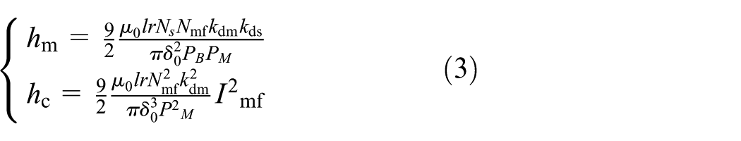
where Nmf and Ns are the numbers of turns of equivalent resultant torque and levitation force windings, respectively; kdm and kds are the fundamental winding distribution coefficient of torque and levitation force windings, respectively; PM and PB are their pole pair numbers; µ0 is the air permeability; r is the inner diameter of the outer stator; l represents the length of motor; δ0 is the equivalent radial length of air gap without rotor eccentricity.
There are only 4-pole inner permanent magnets and no torque windings in the levitation subsystem of the proposed motor, so some parameters in equation (3) can be changed as Imf = If1, Nmf = Nf1, µmf = µf, PB = 1, PM = PM1 = 2, kdm = 1. Here, PM1 is the pair poles of the inner permanent magnets; Nf1 and If1 are the equivalent turn numbers and equivalent current of the inner permanent magnets, respectively, and they are constant; µf is the initial phase angle of the inner permanent magnets. Hence, the coefficient hm will be a constant when the new parameters are substituted into equation (3). When the parameters If1 and µf of the inner permanent magnets, together with the coefficient hm, are constant, from equation (2), it can be obtained that the controllable levitation force amplitude is only linear with the levitation force winding current magnitude Is, and its direction only relies on the levitation force winding current initial phase angle λs. So it is easy to realize the linear control of the controllable levitation force, and the self-decoupling of the controllable levitation force and torque has been realized in the topology.
When the rotor deviates from O to O′, the air gap of the inner stator will change from δ0 to δ1, and the air gap of the outer stator will change from δ0 to δ2, as shown in Figure 3. If the torque subsystem of the proposed motor is shielded, the unilateral magnetic force F1′ will be only generated by the levitation subsystem. Thus, hc = hc1, and hc1 is the coefficient of the F1′ when the levitation subsystem operates only. Hence, some parameters in equation (3) can be changed as Imf = If1, Nmf = Nf1, PM = PM1 = 2, kdm = 1, and the hc1 can be expressed as

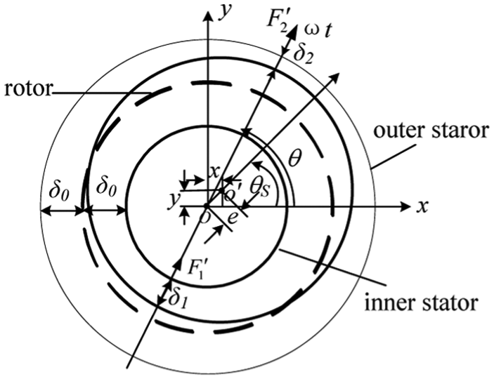
Air gap distribution of rotor eccentricity.
If the levitation subsystem of the proposed motor is shielded, the unilateral magnetic force F2′ will be generated by the outer stator only. Thus, hc = hc2, and hc2 is the coefficient of the F2′ that the torque subsystem operates only, so it can be expressed as

where PM2 is the pair poles of the outer permanent magnets; Nmf2 and Imf2 are the equivalent turn numbers and equivalent current which synthesized by the torque windings and the outer permanent magnets.
Because the pair poles PM2 is 9, the coefficient hc2 will be far less than hc1. Due to the magnetic flux paths of the two subsystems are independent of each other, the total coefficient of the unilateral magnetic force hc. can be obtained by hc1 + hc2. Consequently, equation (2) can be simplified as follows when both the initial phase angle λs and µmf are fixed

In brief, from equation (6), it can be known that the first part is the controllable levitation force which is proportional to the amplitude of the levitation force winding current Is, due to the coefficient km = hmIf1 cos(µmf − λs), which is a constant. The second part is the unilateral magnetic force which is a resultant force when the torque and levitation subsystem run together.
Optimization of the motor parameters
Ignoring the resistance of the five-phase double-stator BBLDC motor’s windings, the size
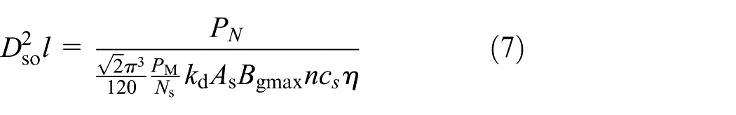
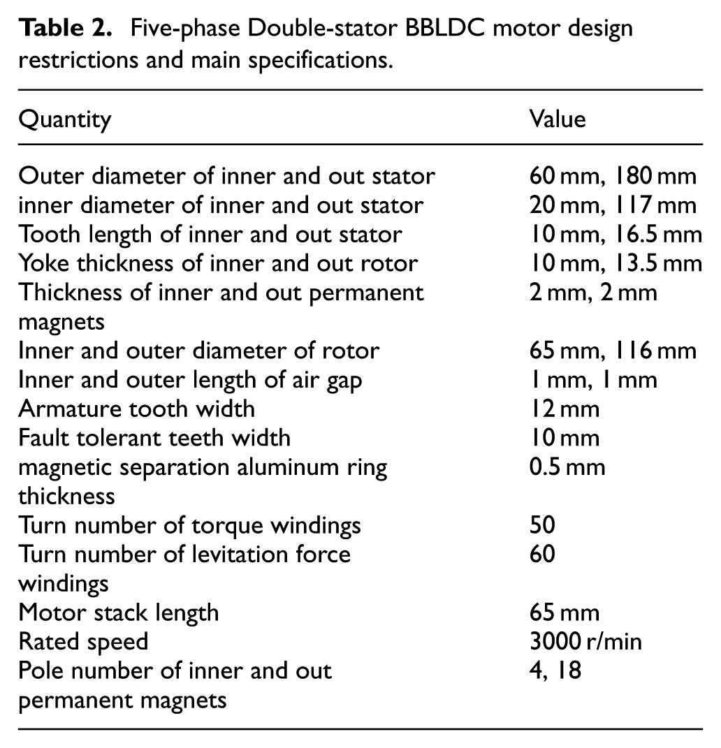
According to the experience value, the relevant parameters of equation (7) are given to calculate the sizes of
Five-phase Double-stator BBLDC motor design restrictions and main specifications.
Optimization of levitation subsystem
By optimizing the shape of permanent magnet and stator, the ideal air gap magnetic flux density waveforms can be obtained, and the cogging ripple of the motor can be weakened. Figure 4(a)–(c) shows the optimization of the inner permanent magnet in the eccentric distance koff1, pole arc coefficient kemb1, and slot distance kbs01 of inner stator, respectively. Due to little effect of the parameters on each other, they can be optimized independently. It can be seen from Figure 4 that the cogging ripple can get the minimum value when koff1 = 10 mm, kemb1 = 0.84, kbs01 = 2 mm. Considering the wire diameter and coiling easily, the value of kbs01 can be set as 2.2 mm. And then the optimized air gap flux density waveform is shown in Figure 4(d), which is in desirable sine shape.

Optimization of levitation subsystem: (a) permanent magnet offset, (b) permanent magnet pole arc coefficient, (c) stator slot distance, and (d) air gap flux density.
Optimization of torque subsystem
The torque subsystem is BLDC motor, so the eccentric distance koff1 is 0 mm. After the optimization, the values of kemb2, kbs02, and the stator fault tolerant tooth arc β1 are 0.84, 2.2 mm, and 13.8°, respectively. Figure 5(a) shows the variation of the flat width of the back electromotive force (EMF) with the change of the armature tooth arc β2. When the armature tooth arc β2 changes from 13.8° to 17.8°, the flat width of back EMF will be more stable and wider, and it becomes more and more close to 144°. When the arc β2 changes from 17.8° to 23.8°, the back EMF flat width increases slowly, but the distortion will enhance, so β2 can be set as 17.8° eventually.

Optimization of torque subsystem: (a) variation of back EMF with β2 and (b) comparison of torque between 20-slot/18-pole and 20-slot/4-pole motors.
Due to the high independence between the torque and levitation subsystem, the torque subsystem can be designed independently. Compared with the ISCW topology, the FSCW structure has higher torque/power density and smaller torque ripple. Thus, the torque subsystem uses 20-slot/18-pole FSCW topology, which has the advantages of weakening the tooth harmonic and improving the waveform of the EMF effectively. For comparison, a five-phase double-stator BBLDC motor with 20-slot/4-pole ISCW topology is designed. The output torques of the two kinds of motors are compared in Figure 5(b). It can be seen that the average torque and ripple of the FSCW topology are 8.09 N m and 3.5%, respectively, and the values in ISCW topology are 2.34 N m and 15.0%, respectively. It can be concluded that when the motor in the same condition, the average torque of the 20-slot/18-pole FSCW topology is 3.46 times of the 20-slot/4-pole ISCW topology and the torque ripple is only 23.3% of the latter.
FEA validation of the model
Self-decoupling of torque and levitation subsystem
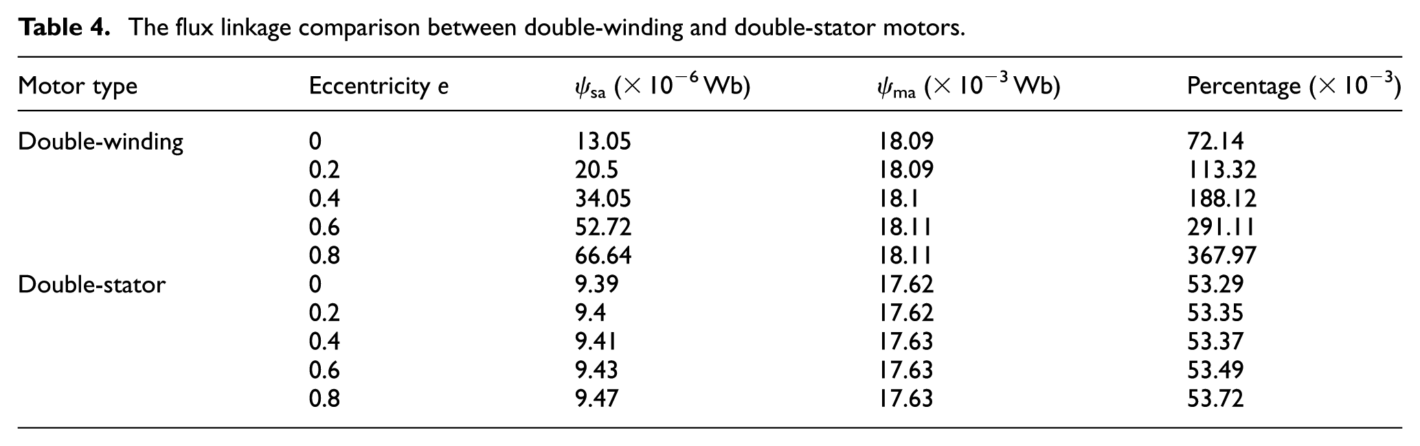
Due to the inner and outer rotors are isolated by the magnetic separation aluminum ring, the magnetic flux path of the two subsystems are independent with each other, as shown in Figure 1(b), so the torque and levitation force subsystem are decoupled in structure. To compare the coupling characteristics between the double-stator and double-winding bearingless motor, a simulation model using the FEA method is set up for the double-winding BBLDC motor, and the main parameters are shown in Table 3. The numbers of turns of torque and levitation windings are equal in two motors, respectively. In order to analyze the coupling between torque windings and levitation force windings, all of the permanent magnets are shielded in the two motors; meanwhile, the currents of the levitation and torque winding are set as 0 and 1 A, respectively. When the rotor eccentricity is different, the flux linkage of the torque windings and levitation windings of A phase is recorded in Table 4. The variation ψma to ψsa are the flux linkage in the torque windings and levitation windings caused by torque winding current. It can be seen that in the double-winding BBLDC motor, the flux linkage ψma is kept constant, but ψsa increases quickly with rotor eccentricity, and the ratio of ψsa to ψma is from 72.14 × 10⁻³ to 367.97 × 10⁻³%. However, the condition of the double-stator motor is different, with the increasing of rotor eccentricity, the flux linkage ψma is also kept constant, but the ψsa increases very little, and the ratio of ψsa to ψma varies from 53.29 × 10⁻³ to 53.72 × 10⁻³%. Consequently, the coupling between the torque windings and the levitation force windings of the proposed motor is much less than that of the double-winding BBLDC motor.
Double-Winding BBLDC motor design restrictions and main specifications.

The flux linkage comparison between double-winding and double-stator motors.
The comparison of controllable levitation forces (rotor eccentricity is 0 mm) of the proposed motor is shown in Figure 6, one is with the torque subsystem and another without. The FEA results show that regardless of no matter whether the torque subsystem is applied or not, the controllable levitation forces are almost the same, which review that the effect of the torque subsystem on the levitation subsystem can be negligible. So the torque and the levitation subsystem are highly independent.

Comparison of controllable levitation force between with torque subsystem and without torque subsystem.
Analysis of levitation force
The FEA and mathematical model calculation results of the levitation force have make a comparison in Figure 7, when the current of levitation force winding is 0 A, the levitation force is referred to unilateral magnetic force. For the auxiliary bearings, the maximal eccentric displacement of the rotor is from −0.3 to 0.3 mm and the maximum magnitude of unilateral magnetic force is 216 N. Meanwhile, the unilateral magnetic force corresponding to the different rotor eccentric displacement is shown in Figure 7(a)–(c). Assume that the rotor only offsets 0.2 mm to the y-axis negative direction and no eccentricity in x-axis direction, then the unilateral magnetic force can be divided into two kinds of situations. First, if the torque subsystem is shield, the unilateral magnetic force Fin_y is generated by offsetting toward the inner stator. Its average value is −133.18 N and it orients to the negative y-axis as shown in Figure 7(a). Second, if the levitation subsystem is shield, then the unilateral magnetic force Fout_y is generated by offsetting toward the outer stator. Its average value is −6.47 N and it orients to the negative y-axis too as shown in Figure 7(b). It can be seen from Figure 7(c) that when the two subsystems of the motor work together, the total unilateral magnetic pull is −140.75N, and that is the sum of the Fin_y and Fout_y approximately. So the FEA results correspond with the mathematical model calculation results basically, and the error between them is less than 5.7% (Table 5).

Unilateral magnetic force with respect to eccentric displacement and resultant levitation force with respect to currents: (a) unilateral magnetic force with inner stator operates alone, (b) unilateral magnetic force with outer stator operates alone, (c) unilateral magnetic force with two stators operates together, and (d) Relationship between the resultant levitation force and levitation currents.
Comparison between mathematical model and FEA results of unilateral magnetic forces.

FEA: finite element analysis.
The amplitude of the controllable levitation force increases with the current of the levitation force winding current Is. When the current Is is less than 4 A, the levitation force is linear, and the FEA results are consistent with the mathematical model calculation results. When the current increases to 4 A, the error between them becomes large due to the motor core tends to saturation, as revealed in Table 6. So, the maximum levitation force current can be set as 3 A, and the resulting maximum controllable levitation force is 283 N. Therefore, when the motor runs in the unsaturated zone, it can be obtained that the controllable levitation force amplitude is only linear with the levitation force winding current magnitude Is, and its direction relies on the angle difference between the equivalent resultant torque and the levitation force winding current, given by µmf−λs, from equation (2). Thus, it is easy to realize the directional control of the levitation force through this conclusion.
Comparison between mathematical model and FEA results of controllable levitation forces.

FEA: finite element analysis.
The resultant levitation force is the sum of the controllable levitation force and the unilateral magnetic force which is expressed as equation (6). Assuming that the rotor offsets 0.2 mm to the y-axis negative direction, there are three kinds of states in the resultant levitation force. First, when the controllable levitation force is 0 N (the levitation force winding current value Is is 0 A), then the resultant levitation force is only caused by the unilateral magnetic force, whose average value is −140 N and it orients to the negative y-axis, as shown in Figure 7(d). Second, when the current value Is is about 1.5 A, the controllable levitation force is equal to the unilateral magnetic force, but in the opposite direction, so, the resultant levitation force is close to 0 N. The third, when the current value Is continues to increase, the controllable levitation force will be larger than the unilateral magnetic force, and the resultant levitation force is greater than 0 N and points to the positive y-axis, so this force can make the rotor return to the balance position.
In conclusion, the resultant levitation force is approximately a straight line that does not pass through the origin. Hence, it can be concluded that in the linear region, the proposed motor is easy to realize the stable levitation by adjusting the levitation force winding current value.
Experimental verification
To verify the accuracy of the theoretical analysis, an experimental prototype of the five-phase double-stator BBLDC motor is made. The main prototype parameters are as follows: outer diameter of the outer stator is 180 mm, the thickness of permanent magnets is 2 mm, the average length of air gap is 1 mm, and rated power PN is 2.5 kW.
The feasibility and superiority of the proposed motor are verified by the analysis of the rotor levitation control and the speed regulation performance. Figure 8(a) shows the dynamic rotation speed waveforms of the prototype which changes from 2000 to 3000 r/min, including channel 1 for speed and channel 2 for the rotor eccentric displacement in x-axis. When the motor speed decelerates from 3000 to 2000, the rotor eccentric displacement in x-axis is shown Figure 8(b). It can be seen that the speed can track the given speed quickly, and the speed error is less than 5%. Meanwhile, disturbance of rotor displacement in the x-axis direction is much smaller than 0.3 mm, so the auxiliary bearing is static, and the rotor is suspended in the air stability. Both the acceleration and deceleration process of the motor have little influence on the rotor eccentricity, so the decoupling property between the torque windings and the levitation force windings is verified.
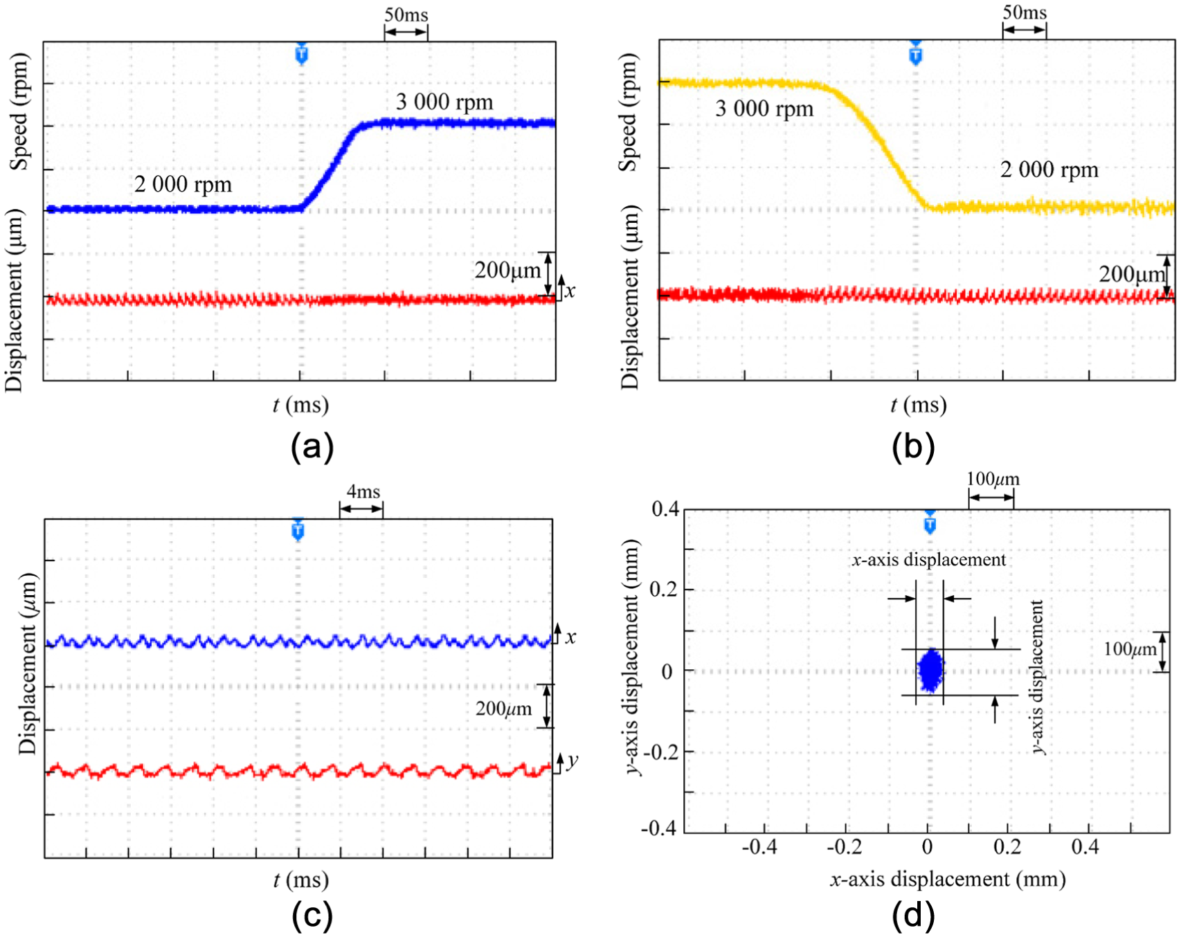
Experimental results: (a) the eccentric displacement in x-axis during the speed improvement (50 ms/div, 1500 r/min/div, 200 µm/div), (b) the eccentric displacement in x-axis during the speed reduction (50 ms/div, 1000 r/min/div, 200 µm/div), (c) the eccentric displacements of x-axis and y-axis direction when the rotor runs at 3000 r/min (4 ms/div, 200 µm/div), and (d) radial displacement relations between x and y direction (100 µm/div, 100 µm/div).
When the motor operations steadily at 3000 r/min, the maximal value of the rotor eccentric displacement in x-axis is 46 µm, while the value in y-axis is 82 µm, and they are much smaller than 0.3 mm, as shown in Figure 8(b). In addition, the rotor eccentric displacement in y-axis direction is larger than that of x-axis direction for the influence of gravity, so the rotor eccentric orbits are an elliptical or nearly circular shape, as shown in Figure 8(c).
Conclusion
This article proposes a novel structure of five-phase double-stator BBLDC motor. The topology characteristics and operation principle of the motor are described in detail. The mathematical model is deduced for the levitation force and the simulation model is optimized by the FEA software; the results confirm that the proposed BBLDC motor has the superior decoupling characteristics compared with the double-winding BBLDC motor. In addition, the experimental results verify the theoretical analysis. The motor has the following properties.
First, the air gap field generated by the torque winding current interacts with the one generated by the outer permanent magnets to realize the rotor rotation. The air gap field generated by the levitation force winding current interacts with the one generated by the inner permanent magnets to realize the rotor levitation stable levitation of the rotor, the torque and levitation subsystem are independent of each other.
Second, fine performance of levitation and rotation are visibly shown by the experimental and FEA results due to the self-decoupling characteristics between the torque and levitation windings. The controllable levitation force control is independent of the torque control, which is linear with the levitation force winding current value in unsaturated state. Thus, there are many control strategies for selecting and applying.
Finally, due to the strong independence between the torque and levitation subsystem, the torque subsystem can be designed individually. The 20-slot/18-pole FSCW topology is used in torque subsystem, and the fault tolerance performance is made notable improvements because of the fault tolerant tooth on the outer stator, so it lays a theoretical foundation for the research of fault tolerance and control strategy. Thus, the proposed motor can not only increase the motor torque density but also decrease the torque ripple, and the performance is superior and the application is wider.
Footnotes
Academic Editor: Jianqiao Ye
Declaration of conflicting interests
The author(s) declared no potential conflicts of interest with respect to the research, authorship, and/or publication of this article.
Funding
The author(s) disclosed receipt of the following financial support for the research, authorship, and/or publication of this article: This work was sponsored by National Natural Science Foundation of China (51675244), Key Research and Development Project of Jiangsu Province (BE2016150), Jiangsu Province “333 Project” Research Projects (2014), Jiangsu Province “Qinglan Project” (2014), Priority Academic Program Development of Jiangsu Higher Education Institutions (2014), and the Graduate Education Innovation Project of Jiangsu Province (KYLX15_1071).