
Abstract
According to the conventional well cementing method, the cementing sliding sleeve, as a key part of the casing, needs to be opened by switch tool step by step to conduct fracture with coiled tubing. However, it usually needs switch tool to locate accurately, which is indeed a challenge. This article proposes a set of fracturing sliding sleeve with six-opening-degree and hydraulic switch tool working with coiled tubing–enabled fracturing sliding sleeve. The three-dimensional models, finite element analysis, and flow analysis of the tool are also adopted, which can validate the rationality of the tool’s structure. The experimental tests show that the sliding sleeve can be opened or closed with multi-opening degree easily and overcome the gas coning, which can fully meet the requirements of down-hole operation. In addition, the switch tool can open or close the sliding sleeve under lower pressure, and it has a high success rate to open or close the sliding sleeve by coiled tubing without precision location.
Introduction
Shale gas, existing in sedimentary basin, has a very good development potential for its wide distribution, and it is the ideal energy resource in addition to oil and gas. Due to its special mechanism of aggregation, it cannot be extracted by conventional method. With the development of the shale gas drilling technology, horizontal well fracturing technology can improve the single well production with the greatest degree during the development phase of shale gas. It is evaluated as an important way to the development of shale gas. Researching a large number of the current fracturing cases1,2 of shale gas horizontal well, two methods are commonly used: one is cable perforation and pumping bridge plug (referred to here as plug-and-perforate) and the other is opening the fracturing sliding sleeve by dropping-down balls with different sizes in proper order (referred to here as BDFS). For the first method,3–5 the drilling plug technology is needed to be performed which leads to the increases in operation time and risk, and the process usually adopts hydraulic fracturing and jet perforation, so it is complex. For the second method,6,7 it is usually a single process: once we want to close a sliding sleeve in certain level for selective production, the special tool is needed to put into the borehole, which results in complex processes. Meanwhile, milling the balls and ball seat is needed for later production considering that the ball seat in the borehole will affect the diameter of the oil channel, which increases the operation time and cost.
A new well completion technology named coiled tubing-enabled fracturing sliding sleeve (referred to here as CTFSS) is proposed in last decade.8–10 It uses cementing cement and sliding sleeve to implement well completion. And then shale gas horizontal well fracture is carried out by the coiled tubing (CT). Due to the good working effects combining with time and cost saving, it is proved to be an efficient, safe, and better operation ability reservoir reconstruction method. This technology uses switch tool carried by CT to open or close the sliding sleeve, thereby performing oil well operation such as fracturing stimulation, selective exploitation and closing the seal leakage layer, which greatly improved the working efficiency. However, at present, the precision location technology is required when opening or closing the sliding sleeve by CT carrying switch tool, but the precision location technology does not have a breakthrough. Recently, many CT-enabled fracturing tools for shale gas exploitation have been developed, such as retrievable CT fracturing tool, 11 tools controlling the depth of CT-enabled fracturing operation, 12 and tools for CT-enabled annular fracturing for horizontal well.13,14 But switch tools of CTFSS without accurate positioning are rare. To develop such a set of tool, it can not only save a lot of operation time, but also can guarantee the validity for opening the sliding sleeve.
The purpose of this article is to develop the fracturing sleeve of CT for multistage fracturing of shale gas horizontal well. The tool has simple structure and it is easy to work. The switch tool can open or close the sliding sleeve with lower pressure, and it has a high success rate to open or close the sliding sleeve by CT without precision location. The principle, structure, and analysis of the fracturing tool are reviewed below.
Fracturing technology for shale gas horizontal well
The shale gas horizontal well fracturing has become the main mode of the exploitation of shale gas efficiently. The fracturing methods and processing steps are directly related to the production and the quality of the follow-up operations.
Fracturing method
There are generally three main multistage fracturing methods for shale gas horizontal well. The first method is the hydraulic fracturing technique using cable perforation and composite bridge plug separation. While using plugging-and-perforating segmentally, composite bridge plug is used to separate fracturing segments. After the bridge plug is pumped into the borehole, the casing over the bridge plug will be perforated by setting logging cable. Then hydraulic fracture is implemented on the borehole of the cased well, and finally, the CT is used to drill out the plug to starting production. However, the technique requires a high pressure performance for the casing, and the service life of hydraulic fracturing tool is also limited, which makes it hard to drill plug for the long horizontal section. And the comprehensive cost is higher.
The second method is the multi stage fracturing technology of pitching slip sleeve. Usually, the sliding sleeve is opened in different sections by dropping balls with different diameters through hydraulic packers. This method does not require perforation and has no pollution to the layer, but the maximum fracturing layers are limited by the number of balls that are allowed to throw in. Meanwhile, the ball seat impacts the diameter of oil channel, which does not benefit the following workover operation. Moreover, the technique is just a single process that cannot be applied to selective production. When the packing interval is too short, the cross strata phenomenon may appear and the gas coning may be out of control.
The third method is the multistage fracturing technique with switchable cementing sliding sleeve. First, the sliding sleeve should be put on the position of the oil layer selectively, and then it will be opened by switch tool carried by drill pipes, tubing, or CT after well cementation. Finally, the fracturing operation can be carried out with the same pipe string. The technique allows the fracturing operation to be finished continuously at a time and no perforation and extra packer layer are required, which saves the operation time and cost. After the fracturing, the space of the casing is unobstructed which brings convenience to the following workover operations. Since the sliding sleeve can be opened or closed for many times, it will improve operation efficiency greatly, and it can also open or close fracturing sliding sleeve in proper order, which can meet the technical requirements on shale gas well multi-layer hierarchical reformation and selective exploitation. The structure of tool string of this kind of methods is shown in Figure 1.

The schematic diagram of tool string.
The processing steps
The processing steps are as follows:
Running the tool string for well completion, setting the liner hanger, and cementing;
Setting the hanging packer after bump-pressure of the cement plug;
Releasing and then lifting the releasing sub and the inserted sealing section out of the tie-back cylinder. Flushing the well circularly. Pulling out the running string and opening the wellhead for solidification.
After the cement setting, replacing with new inserted seal for the former tubing string, attaching the resident pipe of switch tool on the top of inserted seal, running tubing string, and completing inserted sealing;
Running CT-enabled tool string with hydraulic switch tool;
Opening the sliding sleeve of the bottom layer;
Lifting the CT-enabled tool string until the switch tool is still in the resident pipe;
Fracturing the production layer, then setting the switch tool in the resident pipe and closing the sliding sleeve of that layer;
Opening the sliding sleeve of the above layer;
Repeating steps 5–8 until all the fracturing is finished;
Pulling the CT-enabled switch tool string;
Running the CT-enabled tool string for sand washing and then carrying out sand-flushing operations.
Running CT-enabled switch tool string and opening the sliding sleeve of the required production layer selectively.
CT-enabled fracturing sliding sleeve
Compared with the traditional tools, CTFSS tools require no accurate location and have no impact on oil channel. Also the service life can reach 20 times, which is much more than the traditional tools.
The structure of the switch tool
The structure of this kind of hydraulic switch tool under different pressure conditions is shown in Figure 2 and 3, which consists mainly of sub, mandrel with pressure hole, sheath connected to the mandrel, jaw, bottom hinge root, knuckle joint, slip bracket, spring sleeve, connecting sleeve, piston, cylinder sleeve, and compress spring.

The structure of hydraulic switch tool in unpressurized condition.

The structure of hydraulic switch tool in pressurized condition.
The structure of the fracturing sliding sleeve with six-opening-degree
The structure of fracturing sliding sleeve with six-opening-degree shown in Figure 4 is simple, but it is novel. During the working process, a pulling force from the jaw of switch tool is loaded on the jaw of the sliding sleeve and the sliding sleeve will be forced to rotate due to the restriction of pin which moves along the track groove of the sliding sleeve. Therefore, the space between the fracture slot and fracture channel slot will be locked and opened gradually, so as to realize the open of the sliding sleeve with multi-opening gradually.

Structure of fracturing sliding sleeve with six-opening-degree.
The working principle of fracturing sliding sleeve
When the opened jaw of switch tool jams the jaw welding on the installation groove (7) of the sliding sleeve, the sliding sleeve body (4) will move up. The pin (12) set on the lower sub (3) is sliding connection with the track groove of pin (9) on the sliding sleeve body (4), as shown in Figures 5 and 6. During the moving up and down process of the sliding sleeve body (4), the pin (12) slides along the track groove of pin (9) from position 1 to position 7 in Figure 7. Therefore, the sliding sleeve body (4) is forced to rotate step by step, which makes the fracturing groove (10) and fracturing channel groove (6) open or close gradually with the opening degree of 4, 8, 12, 16, 20, 24 to control the size of fracturing channel.

The schematic diagram of sliding sleeve with multi-opening degree.

The schematic diagram of track groove of pin of sliding sleeve.
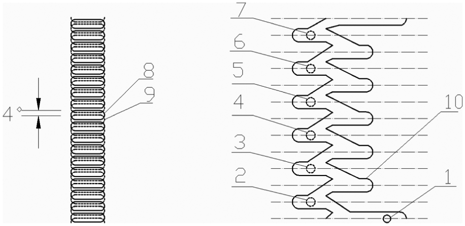
The principle of changing the size of opening the sliding sleeve.
For example, the sliding sleeve body (4) will be forced to rotate when the pin (12) moves from the initial position 1 to the second position 2. Correspondingly, the fracturing channel groove (6) on the sliding sleeve body will rotate an angle of 4° from position 8 to position 9 with the rotating of the sliding sleeve body. Since the initial position 8 of the fracturing channel groove coincided with the fracturing groove (10), the second position 9 of fracturing channel groove had an angle difference of 4° with the fracturing groove. This is the meaning of opening size of 4°. The angle differences between fracturing channel groove (6) and fracturing groove (10) will be 8°, 12°, 16°, 20°, and 24° when the positions of pin are 3, 4, 5, 6, and 7, respectively.
The working principle of switch tool
When fracturing sliding sleeve is needed to be closed during the process of CT operation, first of all, two independent switch tools connected reversely up and down on both ends are connected with CT, and then they are put into the well together. At this moment, the jaw of switch tool is in the closed state. When the position of switch tool is over the location of sliding sleeve, pressure can be injected inside the CT. The high pressure liquid in the center hole of mandrel enters the annular space rounded by cylinder sleeve, piston, lower sub, and mandrel through the pressure hole. With the liquid pressure acting on the end face of piston (4), the spring (12) will be compressed. So the spring (9) will overcome the resistance from spring (12) and push the connecting sleeve (10), spring sleeve (6), and bottom hinge root (14) connected with spring sleeve to move axially until the jaw of switch tool is opened by knuckle joint (13). After that, CT is lifted and the sliding sleeve can be closed by the convex platform on the jaw; hence, the leakage layer can be closed or plugged, as shown in Figure 8.

Closing the fracturing sliding sleeve by hydraulic switch tool.
It is known to all that the fracturing sliding sleeve is set in a casing which is about 9 m. Switch tool does not need to accurate the position of the sliding sleeve. The switch tool only needs to pass over the position of sliding sleeve and arrive at the casing under the sliding sleeve. The distance between the position of sliding sleeve and the position that the switch tool arrives at the casing is generally about 5 m. So the CT-enabled tool can locate the switch tool in this 5 m distance. To open the fracturing sliding sleeve during the process of CT operation, two independent switch tools should be docked reversely on both ends up and down firstly and be connected with CT. Then they are put into the well together with the jaw of the switch tool in closed state. When the position of switch tool is above the position of upper button on the sliding sleeve, the pressure is injected inside the CT to open the jaw of switch tool. Putting the CT down into the well continuously, the sliding sleeve can be opened by the convex platform on the jaw. Then fracturing operation and other construction can be performed, as shown in Figure 9. The connection relationship of the jaw of the switch tool and the jaw of the sliding sleeve is shown in Figure 10.
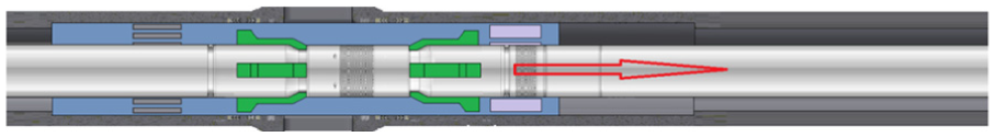
Opening the fracturing sliding sleeve by hydraulic switch tool.

Connection of the jaw of the switch tool and the jaw of the sliding sleeve.
Analysis of major components
For the operation security of fracturing sliding sleeve and switch tool, the finite element analyses are required to check the strengths of the major components such as jaw and its matching component parts.
Three-dimensional finite element analysis of jaw
Jaw and its matching parts are the key components of this hydraulic switch tool. The convex platform is set on the jaw, which is mainly used to match with the sliding sleeve. When the groove of the sliding sleeve is matched with the convex platform of the jaw, the sliding sleeve can be opened or closed smoothly by the switch tool. The 3D solid model of the jaw is shown in Figure 11.

The 3D solid models of jaw.
The ANSYS software is used to simulate the loading condition of jaw when the sliding sleeve is opened or closed. The design defect can be discovered in time by the strength analysis, which can help to improve the stress situation and structural design of the tools. The material of the jaw and sliding sleeve is ASTM4135 whose tension strength is 985 MPa, yield strength is 835 MPa, Poisson’s ratio µ is 0.3, and elastic modulus E is 205,000 MPa. The jaw is meshed by tetrahedral element. The corresponding constraints and loads are applied on it. The maximum lift load is 2 tons applying on four jaws, as shown in Figure 12.

The finite element model (FEM) of jaw.
Based on the above modeling situations, the composite deformation diagram and the equivalent stress diagram of jaw are shown in Figures 13 and 14, respectively.

The composite deformation diagram of jaw.

The equivalent stress diagram of jaw.
From the composite deformation diagram, it can be found that the largest composite deformation of jaw under the extreme working condition is 0.02 mm, which just occurs on the edge of the convex platform. And the deformation is within the scope of the dimensional tolerance. The maximum value of stress is 352 MPa, which occurs on the root of the convex platform. When the safety coefficient is 2, the admissible stress is about 420 MPa, which shows that the analysis stress is less than the admissible stress, and the strength is enough as well. For the sake of security, it is reasonable to further improve the strength.
Three-dimensional finite element analysis of sliding sleeve
The tetrahedron element is used to mesh sliding sleeve. The constraints and loads are applied. The maximum lift load of 2 tons are applied on the ring groove where the upper hinged jaw of switch tool matches with sliding sleeve inside, as shown in Figure 15. Based on the finite element analysis, the composite deformation diagram and the equivalent stress diagram of sliding sleeve are shown in Figures 16 and 17, respectively.

The finite element model (FEM) of sliding sleeve.

The composite deformation diagram of sliding sleeve.

The equivalent stress diagram of sliding sleeve.
Figure 16 shows that the largest composite deformation of sliding sleeve is 0.04 mm under the extreme working condition, which just occurs on the edge of the ring groove where the upper hinged jaw of switch tool matches with sliding sleeve. The deformation is small, and the maximum stress also appears at the same place with a value of 207 MPa. Taking the safety factor as 2, the allowable stress is about 420 MPa, so the stress is far less than the allowable stress.
Flow analysis
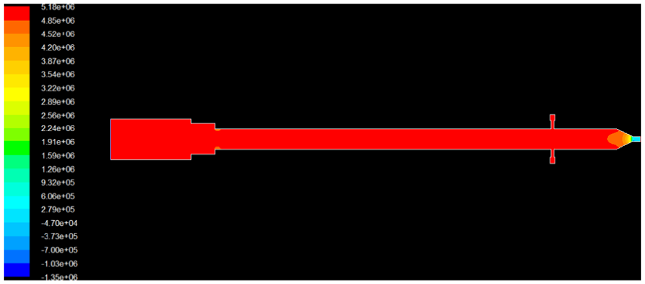
Mandrel is an important component of the hydraulic switch tool. A pressure hole is set on it. Through the pressure hole, the high pressure liquid goes into the annular space formed by cylinder, piston, lower sub, and mandrel to push the piston and eventually open the jaw. Fluent software is used to simulate the fluid flowing situation of the mandrel. According to the design requirements and the specific size, the jaw can be unlocked when the pressure drop through the pressure hole is more than 2.5 MPa. Considering the security, 5 MPa is set as the extreme condition. Taking water as medium, flow analysis about the mandrel has been carried out. If the requirement of pressure drop needs to be satisfied, the entrance velocity should reach 46.6 m/s, as shown in Figure 18. Because its flow velocity is too high, conventional circular flow needed for CT operation cannot reach the requirement. So the related throttle components should be set at the bottom of the switch tool to throttle and decrease pressure.

The pressure drop of mandrel.
The nozzle with 6 mm diameter and internal flow channel of hydraulic switch tool are regarded as a whole in the flow analysis. The pressure drop is shown in Figure 19. When the inlet flow is about 11.3 m/s, the exit pressure drop of pressure hole can reach an extreme throttle and pressure decrease value of 5 MPa. When CT of 2 in is put down into the well, the displacement is about 950 L/min. However, the displacement just need be about 700L/min in order to reach the normal opening pressure. It can be drawn that the analytic result of the displacement is consistent with the conventional circulating flow range of CT operation. And it is realizable to flush the well with small displacement at first and then to open sliding sleeve with large displacement. Besides, the process parameters are appropriate.
The pressure drop of the hydraulic switch tool including nozzle.
Field tests
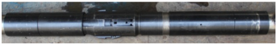
The field tests of opening or closing the sliding sleeve by the designed hydraulic switch tool have been carried out in laboratory as shown in Figure 20. Through pressurizing test, the jaw of switch tool could be opened efficiently when the forefront pressure of the switch tool was more than 2 MPa. During our field tests, it was observed that the sliding sleeve could be opened and closed successfully by the switch tool in the repeated pressurizing test. This hydraulic switch tool was applied to a horizontal well in North America whose vertical depth is 2500m and the horizontal section length is 500m. It was regarded to be reliable in technical performance during the operations of selectively opening or closing layer with convenient operation. The physical of sliding sleeve and switch tool are show in Figures 21 and 22, respectively.

The field pressure test of sliding sleeve and switch tool.

The physical of sliding sleeve.
The physical of switch tool.
Conclusion
The following conclusions are drawn from this work.
For multistage fracturing technique with switchable cementing sliding sleeve, a set of fracturing sliding sleeve with six-opening-degree and hydraulic switch tool have been designed. Accurate positioning is not needed for this tool with the help of the running CT, and the sliding sleeve can be opened or closed with multi-opening degree, which makes the gas coning avoided.
The 3D finite element analysis and flow analysis of the key parts of switch tool have been carried out by engineering software. For the sling sleeve, the 3D finite element analysis of key part has also been conducted. The result shows that the structure of the tool is reasonable and the design of the relevant components conforms to the technical parameters.
Through laboratory tests and field applications for this kind of tools, it shows that the tool can successfully open or close the sliding sleeve in a low-pressure situation. With reliable technical characteristic, it is convenient to be handled and used repeatedly.
Footnotes
Academic Editor: Jianqiao Ye
Declaration of conflicting interests
The author(s) declared no potential conflicts of interest with respect to the research, authorship, and/or publication of this article.
Funding
The author(s) disclosed receipt of the following financial support for the research, authorship, and/or publication of this article: This study was jointly supported by the Hubei Science and Technology Research Plan of China (nos 2013CFC127, 2015CFC855), the Natural Science Foundation of China (no. 51604039), the Yangtze Fund for Youth Teams of Science and Technology Innovation (no. 2016cqt01), the Innovation Foundation of Hubei Cooperative Innovation Center of Unconventional Oil and Gas (no. HBUOG-2014-8), and the Innovation Foundation of Geothermal Resources of Yangtze University (no. GeoTH-2014-03).