
Abstract
As a necessary technical method for shale gas development, hydraulic fracturing technology may cause casing failure while realizing actual reservoir reformation. The fracture-induced inhomogeneous stress generated while the hydraulic fracture is one of the main reasons for the non-uniform compression and failure of the casing. The fracture-induced stress field is mainly related to the fracture net pressure and is unrelated to the initial in-situ stress. The non-uniform load difference near the fracture is more significant, and the mechanical environment of the casing deteriorates. In this study, we combined the fracture-induced stress calculation model and the casing-cement-formation system stress distribution model to analyze the mechanical properties of the system during hydrofracturing. We used the model to calculate the casing stress distribution under fracture-induced stress and analyzed various influencing factors that affect the maximum equivalent stress (MES) on the casing. The studies show that the closer to the fracture, the greater the induced stress and MES in the casing, and the risk of casing collapse increases. The wall thickness of the casing has an influence on the MES. The larger the wall thickness, the smaller the MES. The MES of the casing reaches the maximum value when the elastic modulus of the cement stone is close to that of the stratum. Softer formation increases the potential that the fracture-induced stress transfers to the casing. The potential is responsible for the greater stress of the casing. By increasing hydraulic fracturing stages, reducing hydraulic fracturing wellhead pressure, increasing casing wall thickness and reducing the elastic modulus of cement stone can reduce the casing stress and alleviate casing damage.
Introduction
During the development of shale gas horizontal wells, multistage fracturing technology must be used to increase the connectivity and fluidity of the reservoir.1,2 To form an effective stimulated reservoir volume (ESRV), high operation pressure, large displacement, and perforation staged fracturing technology are generally adopted, which cause severe wellbore integrity problems, especially casing failure, which greatly restricts the development process of shale gas in China.3,4 According to statistics, in China’s Changning and Weiyuan blocks, 36 of the 141 shale gas wells that underwent fracture had casing deformation, and there were 48 casing deformation points.5,6 Casing deformation occurred in 17 of the 34 wells in the Duvernay reservoir of the SS blocks in Canada, and 49% of the wells were deformed. 7 In the Marcellus shale gas field, Pennsylvania, USA; 32 of 62 shale gas wells had casing failure, among which eight were in serious condition. 8
The main factors influencing casing damage can be divided into engineering and geological factors. The engineering factors include casing eccentricity, poor cementing quality, large curvature of the wellbore trajectory, and high operation pressure during fracturing. Sugden et al. 9 noted that thermal stress generated by temperature change during hydrofracturing increases the casing bending stress in the building section and decreases the pressure in the annulus fluid, which causes the casing strength to decrease. On the basis of Sugden’s opinion, Yin and Gao 10 inferred that casing damage is caused by the thermal expansion of the bound fluid in the wellbore annulus and squeezing the casing. Yin and Zhang 11 calculated the temperature change and thermal stress state near the wellbore during hydraulic fracturing. The calculation results showed that the thermal stress reduced the casing tensile strength and collapse strength by 23% and 20%, respectively. Gao et al., 12 analyzed the impact of different cement stone mechanical parameters and cementing operation methods on casing deformation. Some scholars have used numerical calculation methods to research the impact of casing eccentricity and missing cement sheaths on casing failure. The calculation results showed that the integrity of the cement sheath had a more significant impact on casing stress.13–15 In general, the above factors have an impact on casing damage, but are not enough to cause extensive damage to the casing.
Therefore, in recent years, researchers have begun to study casing failures caused by geological factors. Theoretically, hydraulic fracturing squeezes the formation rock apart and finally forms cracks with a certain width. During fracture formation, the stress field of the bottom borehole is redistributed. This may cause the layered stratum to slip and move, thereby squeezing the casing. Microseismic monitoring results also show that faults or natural fractures slip during hydraulic fracturing. 16 Ge and Ghassemi 17 calculated the induced stress and pore pressure distribution around hydraulic fractures and determined the additional pore pressure required to reactivate natural fractures. Lele et al. 18 stated that direct connections between faults and hydraulic fractures cause fault stress and pressure changes to induce fault slip and seismic activity. Thorne and Wallace 19 and Keiiti and Richards 20 established mathematical models of different microseismic amplitudes related to casing deformation, and calculated the fracture or fault radius. Chen et al. 21 and Chen et al. 22 analyzed the influence of various geological factors on casing deformation. Their research shows that the sliding of faults caused by the increase in formation pressure is the main cause of casing damage. Guo et al. 6 analyzed the influence of fault sliding displacement on casing deformation using focal mechanism theory. Fan et al. 23 also carried out similar work, considering the influence of fault sliding and analyzed the impact of fault sliding on the stress state of the casing. Tong et al.’s research group determined the casing deformation mechanism based on the generalized shear activity criterion of geomechanics.24–26 In an intense tectonic activity area, as the fracturing fluid continues to squeeze into faults or fractures, the pressure on the fracture surface increases, which will cause the normal stress of the fracture surface to decrease, the shear stress increases, and the fracture shear slip is induced.
The propagation of hydraulic fractures not only induce stratum slippage and dislocation but also cause rock deformation to spread to all aspects, causing the deformation of the bottom hole to produce fracture-induced stress. If the fracture-induced stress is excessive, the casing may collapse directly. Therefore, this research mainly discusses the influence of the fracture-induced stress field on casing deformation in a horizontal well. In this paper, a new mechanism of casing damage is proposed by combining fracture-induced stress calculation model and casing-cement sheath-formation stress distribution calculation model. The fracture-induced inhomogeneous stress generated while the hydraulic fracture results in non-uniform casing collapse and damage. According to this theory, control measures to reduce the risk of casing failure are proposed.
Horizontal well fracture-induced stress field
Fracture-induced stress field calculation model
During the extension of hydraulic fractures, the rocks around the hydraulic fractures are squeezed by the fracturing fluid present in the fractures, and fracture-induced stress fields are generated around the fractures. As shown in Figure l, during the formation of a hydraulic fracture with a length l, fracture-induced stresses of
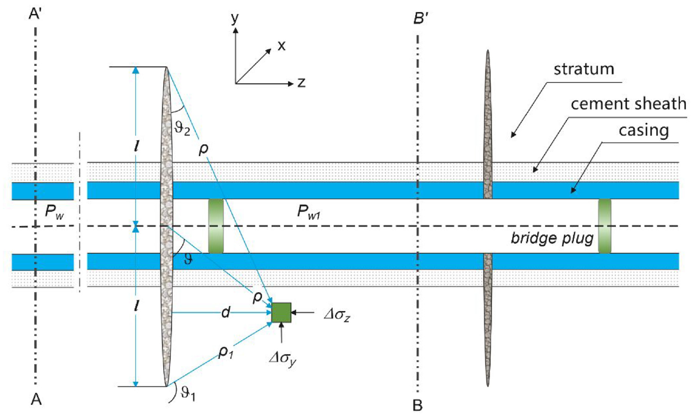
Wellbore mechanical analysis during hydraulic fracturing in a horizontal well.
Sneddon 27 proposed an analytical solution to calculate the stress distribution near a two-dimensional finite-length fracture in an isotropic homogeneous elastic body.
Warpinski and Branagan 28 used the analytical solution to obtain the fracture-induced stress field generated while fracturing.

Where

In the above equation, if
Fracture-induced stress field calculation example
Let us assume that during hydraulic fracturing of a well, its fracture net pressure is 75 MPa which equal to the difference between the fracture pressure and the minimum horizontal in-situ stress. Half-length of a fracture is 100 m. The formation Poisson’s ratio equal 0.2. The relationship between the induced stress generated by hydraulic fracturing and the dimensionless distance of the fracture is shown in Figure 2.

Fracture-induced stress variation with hydraulic fracture distance.
The induced stress on the wellbore section is the
Their difference of the two induced stress gradually firstly decreases and then increases. The difference is close to 0 at a distance of 0.5 times half-length of fracture, and its local maximum at a distance of 1 time half-length of the fracture.
In general, the non-uniform induced stress near the fracture is greater, which makes the casing stress greater. For a larger hydraulic fracturing scale, the hydraulic fracture is longer, and the fracture-induced stress action distance is farther. Therefore, proper control of the fracturing construction scale can help reduce fracture-induced stress as well as the risk of casing collapse.
Mechanical analysis of casing under fracture-induced stress field
Casing stress distribution under fracture-induced stress
The wellbore pressure will act on the cement and surrounding rock through the casing during hydraulic fracturing. The fracture-induced stress generated by hydraulic fracturing also applies to the casing-cement-stratum system. Therefore, the system is affected by uniform internal pressure and non-uniform fracture-induced stress. The horizontal well borehole mechanics model shown in Figure 3 is established.
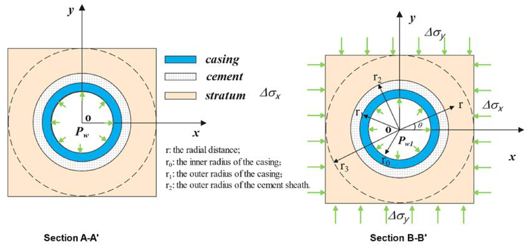
Casing force under fracture-induced stress field.
This model ignores the pore pressure change caused by the cement and rock deformation during the fracturing process and only considers the linear elastic deformation of the cement and rock matrix. We consider the casing-cement-stratum system as concentric rings composed of different homogeneous linear elastic materials, force analysis diagrams of the positive and fractured sections are established as shown in Figure 3. Section A-A’ belongs to the positive fracturing section in the staged fracturing process. At this time, the pressure in the pipe is
Criteria for casing breakage
According to the diameter-thickness ratio of the casing, the American petroleum institute (API) divides casing collapse into four categories, that is, yield strength collapse, plastic collapse, transition collapse, and elastic collapse. 32 In shale gas horizontal wells, thick-walled casing is used in most wells, and most of the casing collapses are yield collapses. The minimum collapse strength for a pipe is modeled by a series of equations, depending on the specified minimum yield strength and cross-sectional dimensions of the tube body. According to API guidelines, it is easy to determine the common casing collapse forms in shale gas horizontal wells in the Sichuan Basin (Table 1).
The type of collapse of common casings in oil fields.

Therefore, it can be considered that the casing under non-uniform load mainly undergoes plastic yielding and collapse, and the fourth strength theory can be used for analysis. If the casing does not collapse, the yield strength of the casing


Where
Calculation examples
We consider the X1 well, a shale gas horizontal well in the Sichuan Basin of China, as an example for analysis. The X1 well was completed with bridge plug perforation and staged fracturing. The calculated data are given in Table 2 in detail.
Basic parameters of the X1 well in this study.

Casing stress distribution
Based on the aforementioned model and basic parameters, the casing equivalent stress distribution during hydraulic fracturing was calculated, which was 3 m away from the hydraulic fracture. It can be seen from the calculation results (Figure 4), the casing equivalent stress changes periodically with the well circumference angle, and the casing inner wall stress is greater than that of the outer wall. In this case, the MES of the inner and outer wall reaches 761 and 430 MPa, respectively.

Casing stress at different circumferential angle.
The casing first yields from the inner wall, then gradually develop outwards, and finally the entire casing collapses. It is generally considered that the yield of a casing wall is equivalent to the failure of the casing. In Figure 4, three blue lines represent the yield limits of three different steels (P110, C90, N80). When the stress anywhere on the casing exceeds this limit, the casing will be a failure. As shown in Figure 4, the MES is greater than 758 MPa (the yield strength of P110). Therefore, it is necessary to choose a higher steel grade above P110 to ensure casing safety under the condition that other conditions remain the same.
Influence of the distances from fractures
Earlier, we analyzed the influence of the dimensionless distance of the fracture on fracture-induced stress, and showed that the non-uniform induced stress near the fracture is greater. In this section, we select several different positions from 1 to 30 m to mechanically analyze the casing. The calculation results are shown in Figure 5. The effective stress on the casing near the fracture is greater. the casing effective stress is greater than 625 MPa (the yield limit of C90 steel) when the distance is less than 10 m. Similarly, the casing effective stress is greater than 758 MPa (the yield limit of P110 steel) when the distance is less than 3 m.

Casing stress at different distances from the fracture.
Influence of the distances fracture half-length
In this section, we select several different fracture half-length from 40 to 100 m to mechanically analyze the casing. The calculation results are shown in Figure 6. The effective stress on the casing in higher fracture half-length is greater. The casing effective stress is greater than 758 MPa (the yield limit of P110 steel) when the distance is great than 90 m. It is worth noting that the fracture length is determined by the fracturing scale. The larger the fracturing scale, the larger the fracture length. Therefore, the casing damage rate can be reduced by controlling the fracturing scale.
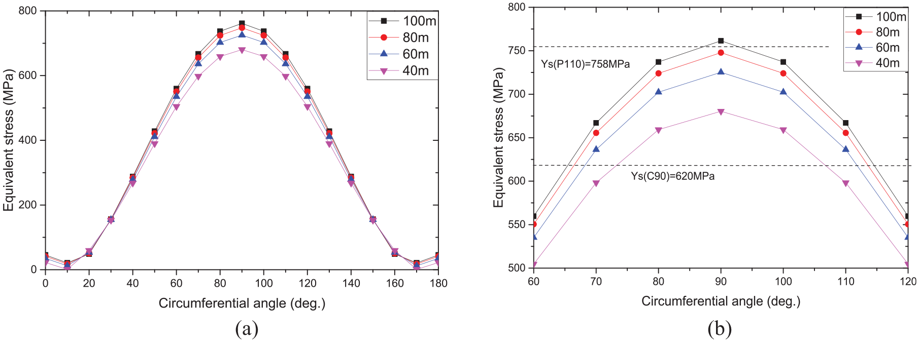
Casing stress of different fracture half-length: (a) full figure and (b) partial figure.
Influence of the casing wall thickness
In order to facilitate comparison and analysis, we selected the casings listed in Table 1, and select a position 3 m away from the fracture, and analyzed the influence of different casing wall thicknesses. As shown in Figure 7, the MES of thick-walled casing is always smaller. For the greater collapse strength of the casing, the MES of the casing is lesser. The MES on the casing decreases from 814 to 754 MPa when the thickness increases from 9.17 to 12.7 mm.

Casing stress of different casing types: (a) full figure and (b) partial figure.
Influence of the cement and formation’s elastic modulus
The elastic modulus of the cement sheath and formation (
As shown in Figure 8, smaller elastic modulus of the formation will cause greater casing stress. In other words, softer formation increases the potential that the fracture-induced stress transfers to the casing. The potential is responsible for the greater stress of the casing. The MES of the casing firstly increases and then decreases with increasing the cement’s elastic modulus. The maximum value of the MES of casing occurs where the cement and formation have an approximately equivalent magnitude of elastic modulus. We suggest reducing the cement’s elastic modulus to reduce the casing stress in hard formation, but we do not recommend to adjust the cement’s elastic modulus to reduce the casing stress in softer formation.
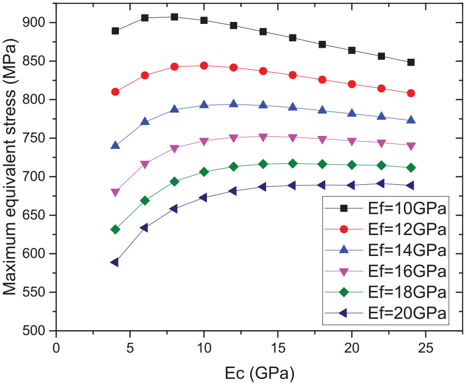
MES in the casing under different elastic modulus of the cement sheath and formation.
Conclusion
A new mechanism of hydraulic fracturing casing damage is proposed by combining fracture-induced stress calculation model and casing-cement sheath-formation stress distribution calculation model. The fracture-induced inhomogeneous stress generated while the hydraulic fracture results in non-uniform casing collapse and damage. According to this theory, control measures to reduce the risk of casing failure are proposed.
The fracturing fluid in the fracture squeezes nearby rocks and generates a fracture-induced stress field around the fracture while fracturing. The size of fracture-induced stress is related to the construction scale (fracture net pressure and fracture length). Large-scale fracturing caused greater fracture-induced stress, which may cause the casing to collapse.
A calculation model that the stress distribution of the casing under non-uniform fracture-induced stress is established, and the law of casing stress distribution under fracture-induced stress is analyzed. The non-uniform induced stress makes the mechanical environment of the casing worse and makes the casing more vulnerable to damage.
By increasing hydraulic fracturing stages, reducing hydraulic fracturing wellhead pressure, increasing casing wall thickness and reducing the elastic modulus of cement stone can reduce the casing stress and alleviate casing damage.
Footnotes
Appendix A
As shown in Figure 3 above, assuming that the entire system is linear elastic, the stress function can be set as:
where
Then, the stress increment and displacement increment caused by the pressure increase and fracture-induced stress in the well can be expressed by equations (A.1) and (A.2).
Where,
At the formation outer boundary
Then,
At the casing inner wall:
The boundary should also satisfy the same stress increment and continuous displacement:
Separating the term without
Where,
Equation (A.5) is used to identify the three unknown parameters in equations (A.10) and (A.11). The other 15 unknown parameters are solved by Gaussian elimination, and the stress increment caused by the fracture-induced stress is obtained.
Handling Editor: Chenhui Liang
Declaration of conflicting interests
The author(s) declared no potential conflicts of interest with respect to the research, authorship, and/or publication of this article.
Funding
The author(s) disclosed receipt of the following financial support for the research, authorship, and/or publication of this article: This work was supported by the China National Key Research and Development Project (2019YFA0708302).