
Abstract
To reduce the herringbone gear transmission vibration and noise, an optimization design method about the meshing vibration of herringbone gear is provided with a controllable sixth-order polynomial function of transmission error. First, the polynomial coefficients of sixth-order polynomial function of transmission error curves can be determined by optimizing the aim at minimum root mean square value of herringbone gear meshing vibration acceleration based on loaded tooth contact analysis method and herringbone gear vibration model. Second, because of the existence of second-order frequency factors in the amplitude of loaded transmission error, the root mean square value of meshing vibration acceleration under the optimization of amplitude of loaded transmission error is worse than the value under the optimization of meshing vibration acceleration in resonant frequency. Third, a numerical simulation of example based on herringbone gear with different order transmission errors is performed, which proves that the herringbone gear train with sixth-order polynomial function of transmission error has the lowest root mean square value of meshing vibration acceleration in the design loads’ range. This study provides evidence that the proposed herringbone gear train with sixth-order polynomial function of transmission error has the significantly better performances in vibration reduction and smooth transmission than that with fourth-order polynomial function of transmission error and second-order parabolic function of transmission error.
Keywords
Introduction
The standard involute cylindrical gear transmission systems, which are widely used in vehicle powertrain system, are sensitive to the manufacturing and installation errors, which can easily lead to edge contact, and induce vibration and damage. 1 In order to improve the quality of gear meshing, tooth surfaces with different orders of transmission errors are obtained by gear profile modification technique.2–4 Experimentation and practice show that gear transmission system with higher order polynomial function of transmission error (H-TE) has lower vibration, better noise performance, and more reliable stability compared to the second-order parabolic function of transmission error (2-TE) system. Due to the interference in the machining process when tooth surface with higher order transmission error than sixth-order polynomial function of transmission error (6H-TE), tooth surface with 6H-TE was selected as the study object. Especially under the precondition for guaranteeing the structural strength, 6H-TE can still effectively reduce vibration acceleration and impact load at the transformation point of traditional transmission error.
Over the last few decades, the researches on the higher order polynomial functions of transmission error were mainly focused on the bevel and hypoid gear sets. Stadtfeld et al. 5 developed a controllable fourth-order polynomial function of transmission error (4-TE) to reduce gear noise and increase the strength of bevel gears by the so-called ultimate motion concept. Wang et al. 6 proposed a methodology to synthesize the mating tooth surfaces of a face-milling spiral bevel gear set transmitting rotations with a predetermined fourth-order motion curve and contact path, and a modified radial motion (MRM) correction in the machine plane of a computer numerical control (CNC) hypoid generator is introduced to modify the pinion tooth surface. Wei et al. 7 convert the theoretical possibility of improving the design of spiral bevel gear by replacing traditional second-order transmission error curve with higher order transmission error curve into a real design method, and the results show preliminarily that replacement of second-order transmission error curve with fourth-order transmission error curve can improve the design of spiral bevel gear. Su et al. 8 proposed a new approach to design and implement a seventh-order polynomial function of transmission error for spiral bevel gears with an aim to improve the loaded distribution of the tooth, and achieved the desired results that the bending stresses of the tooth of seventh-order are less than those of a parabolic one, while the contact stresses remain almost equivalent.
Jiang and Fang 9 proposed a methodology to the involute cylindrical gears that minimizes amplitude of loaded transmission errors (ALTEs) by arranging the tooth surface modifications with an H-TE. A manufacturing process of fabricating a cylindrical crown gear drive is provided with a controllable 4-TE by Lee 10 to reduce the level of gear running noise and to avoid the edge contact. However, in these papers, the influence of H-TE gear system vibration is not discussed which includes meshing impact force and second-order frequency spectrum component of loaded transmission error.
The aim of this work is to propose a methodology to systematically determine a tooth surface modification with 6H-TE that minimizes vibration noise which considers herringbone gear coupling vibration model; the biggest bright spot of this article is the combination of vibration acceleration indicator and higher order transmission error. It is organized as follows. The first segment aims at reviewing the published literatures on the H-TE design of the gear pair, especially for the purpose of transmission stability. In order to solve the problem that the slope of the conversion point is not continuous in the lower order transmission error curve, the curve of the 6H-TE function is designed in section “Design of 6H-TE curve of herringbone gear system.” Upon the consideration of the time-varying meshing stiffness and corner mesh impact excitations, the herringbone gear vibration model supported with rolling bearings is derived in section “Optimum parameter design for 6H-TE curve,” and the parameters of the 6H-TE function are optimized for lower tooth surface vibration noise. Then, the simulation results and discussions about the vibration characteristics of the herringbone gear system with different order transmission error curves are exhibited in section “Analysis and comparison of numerical example,” which is followed by conclusion in section “Conclusion.”
Design of 6H-TE curve of herringbone gear system
Transmission error reflects the lagging angle of driven gear with respect to driving gear, which can be expressed in equation (1)11,12

where φ1 is the rotating angle of driving gear, φ2 is the rotating angle of driven gear, φ10 is the initial rotating angle of driving gear, φ20 is the initial rotating angle of driven gear, z1 is the teeth numbers of driving gear, and z2 is the teeth numbers of driven gear.
In order to solve the problem that the slope of the conversion point (point P in Figure 1) is not continuous in the lower order transmission error curve, the curve shape of the 6H-TE function is designed as shown in Figure 2.

Curve of 2-TE.

Curve of 6H-TE.
In Figure 2, τ is the mesh cycle; τ1, τ2, and τm are the basic parameters of tooth surface; υ1, υ2, υ3, υ4, λ1, and λ2 are the design parameters.
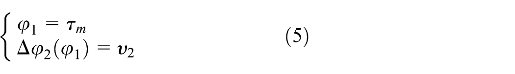
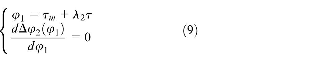
The curve of 6H-TE is expressed in equation (2)
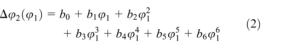
Equations (3)–(9) can be given through the coordinates of points A, B, C, D, and E; the slope of the curve at points B and D is 0, and the values of parameters b0–b6 can be finally determined by equations (3)–(9)


Optimum parameter design for 6H-TE curve
The smoothness of meshing point and the ALTE are used to evaluate the stability of H-TE gear system in the usual dynamic analysis. 8 In practice, however, the factors that affect the vibration of H-TE gear system are varied, which are related to the tooth surface meshing performance mainly including time-varying meshing stiffness and corner meshing impact forces.13,14 In order to obtain the optimum parameters of the H-TE curve, it is necessary to comprehensively consider these vibration excitations when establishing the numerical analytical model.
Dynamic model of herringbone gear
Considering meshing stiffness and corner mesh impact excitations, the herringbone gear vibration model is established in Figure 3. It is a two-parameter (stiffness and damping) model with torsional and lateral vibrations, which means that it includes both the linear and rotational equations of the system’s motion. This model represents a system with 12 degrees of freedom, which is driven by electric motor moment, and loaded with external moment. In this study, the driving gear is supported by cylindrical roller bearings, and the driven gear is supported by tapered roller bearings. It is important to note that meshing stiffness excitation is calculated by loaded tooth contact analysis (LTCA) which includes the stiffness fluctuation and transmission error factors, and backlash is ignored because of the heavy load and relatively low operating speed. 15
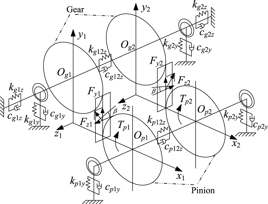
Dynamic model of herringbone gear pairs.
The 12 degrees of displacement freedom can be expressed as
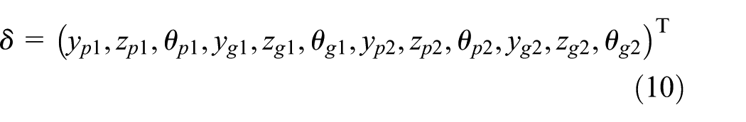
where yij, zij, and θij (i = p, g; j = 1, 2) are the vibration displacements and the vibration angles at the points of Op1, Op2, Og1, and Og2.
According to Newton’s law, dynamic equations of herringbone gear system can be obtained from Figure 3
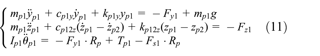


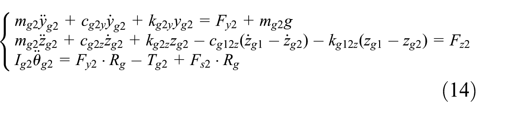
where mp1, mp2, mg1, mg2, Ip1, Ip2, Ig1, and Ig2 are the mass and inertia about pinion and gear; Rp and Rg are the base radii of pinion and gear; cp1y, cp2y, cg1y, cg2y, cg1z, cg2z, kp1y, kp2y, kg1y, kg2y, kg1z, and kg2z are the equivalent support stiffness and damping at the points Op1, Op2, Og1, and Og2; cp12z, cg12z, kp12z, and kg12z are axial the equivalent damping and stiffness of undercuts; Fy1, Fy2, Fz1, and Fz2 are the dynamic meshing forces along the meshing line direction and axial direction; Fs1 and Fs2 are corner meshing impact forces about right and left meshing teeth.
The expressions of Fy1, Fy2, Fz1, and Fz2 are listed in equations (15) and (16)


where Fn1 and Fn2 are the normal meshing forces about right and left meshing teeth; km1 and km2 are the meshing stiffness about right and left meshing teeth; cm1 and cm2 are the meshing damping about right and left meshing teeth; β1 and β2 are spiral angles about right and left meshing teeth, and they have opposite direction as β1 = −β2; and Δφn1 and Δφn2 are the transmission error deformations of right and left meshing teeth, which can be obtained by equation (2).
The tooth surfaces of modified herringbone gears are defined directly from 6H-TE function; 9 the torque transfer analysis model of herringbone gear is established based on the technologies of TCA and LTCA, and on this basis, tooth surface meshing stiffness and corner meshing impact force are obtained. 15
Parameter optimization for 6H-TE curves
The relative vibration acceleration along the meshing line direction is selected as optimization objective function in order to get the optimal design parameters of 6H-TE curve. Because the herringbone gear transmission system usually operates in a wide range of torques, three torque conditions Tm1, Tm2, and Tm3, which correspond to the operation weighting coefficients of ω1, ω2, and ω3, are chosen as the design and optimization conditions.
Optimization function of herringbone gear with sixth-order transmission error based on meshing vibration optimization is established in equation (17)

where f1, f2, and f3 are the optimization objective functions under three operating conditions; yi (i = 1, 2, &, 6) are six design parameters, respectively; limin and limax are the boundary values of optimization variables.
The optimization is an iterative process of solving the TCA and LTCA calculation programs by changing the contact condition between the meshing teeth surfaces. Optimization variables are the design parameters, optimization objective is meshing vibration acceleration (MVA) of herringbone gear, and there is obviously no analytical expression equation between them.
Genetic algorithm is good at solving global optimization problem, compared to the traditional optimization algorithm; genetic algorithm can jump out of local optimum and find the global optimal results, and genetic algorithm allows the use of very complex adaptation degree function (objective function), and can change the scope of variable restrictions.16–20 So, genetic algorithm is especially suited for 6H-TE parameter optimization.
A solution process of the optimization model was given based on an improved genetic algorithm, 21 and the detailed analysis and calculation processes of improved adaptive genetic algorithm and 6H-TE parameter optimization are shown in Figures 4 and 5, respectively.

Detailed process of improved adaptive genetic algorithm.
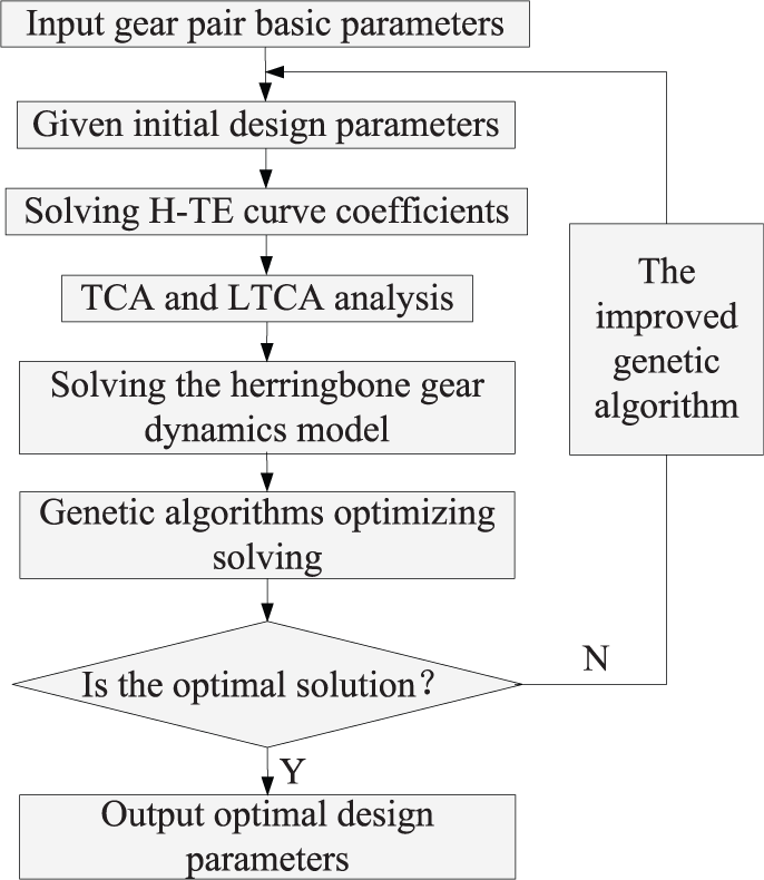
Detailed process of 6H-TE parameter optimization.
Analysis and comparison of numerical example
The basic dynamic parameters of single-stage herringbone gear transmission system are listed in Table 1. Then, the specific example is given to analyze the dynamic characteristics of herringbone gear with different order transmission error curves under the given working conditions. In Table 1, the load conditions and operation weighting coefficients were chosen by the actual working conditions which are provided by the cooperative enterprise.
Single-stage herringbone gear parameters.

Result comparison analysis between different optimal objects of meshing vibration and ALTE
In order to compare the results from different optimal objects of MVA in this article and of ALTE in traditional literatures, the optimization results of 6H-TE curve parameters are obtained in Table 2 using the optimal design method proposed in section “Optimum parameter design for 6H-TE curve.”
Optimization results of 6H-TE curve parameters.

ALTE: amplitude of loaded transmission error; MVA: meshing vibration acceleration.
In Figure 6(a), the ALTE value is 2.4″ in optimization of MVA and 2.2″ in optimization of ALTE; the value for the latter is smaller than for the former, but the latter has two more inflection points than the former (corresponding to the second-order harmonic spectrums in Figure 6(b)). In order to further compare the overall vibration performance of the herringbone gear system under two kinds of optimization objectives, Figure 7 shows the MVA response with different rotational speeds.
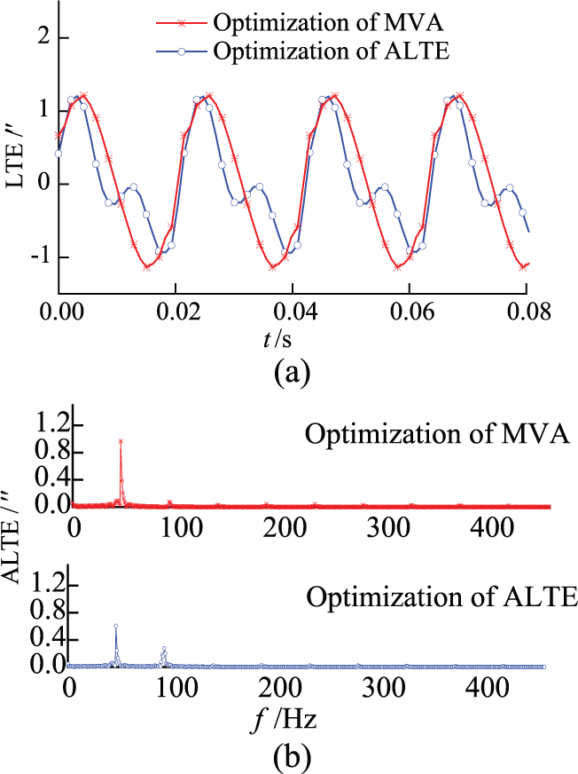
Component comparison of LTE under two optimization conditions (828 N·m): (a) time domain and (b) frequency domain.

Rotational speed diagram of the relative vibration acceleration (828 N·m).
Because of the existence of second-order frequency factors in the optimization of ALTE, the root mean square (RMS) values of acceleration peaks in Figure 7 which correspond to the 1/3, 1/2, and 1 resonant frequencies are obviously greater than the corresponding values in the optimization of MVA. And when the rotational speed reaches the resonance speed, two kinds of tooth vibration response values tend to be the same.
The RMS value of MVA in Figure 8 is 16.95 m/s2 under the optimization of MVA, which is smaller than the value of 22.40 m/s2 under the optimization of ALTE. In conclusion, the amplitude value of LTE cannot completely determine the levels of the meshing vibration and noise. To ensure the good results of vibration and noise reduction, it is essential that RMS value of MVA should be chosen as optimization objective when designing the parameters of 6H-TE curves.

Vibration acceleration response of different optimizations (828 N·m).
Result comparison with different order transmission errors
Herringbone gear tooth surfaces with 2-TE, 4-TE, and 6H-TE were designed, respectively, by the optimization method which was proposed in section “Optimum parameter design for 6H-TE curve” and the optimization target of ALTE. Corner meshing impact force and MVA are, respectively, calculated and compared.
When the load is less than 450 N·m (point A) in Figure 9, the ALTE value of herringbone gear with 6H-TE is bigger than 4-TE and 2-TE, because the real contact ratio of herringbone gear with 6H-TE is the lowest of all. With the load rising to more than 500 N·m (point B in Figure 9), the real contact ratio of herringbone gear with 6H-TE increased and reached maximum of all, and therefore, the smooth performance of 6H-TE curve is better than 4-TE and 2-TE.
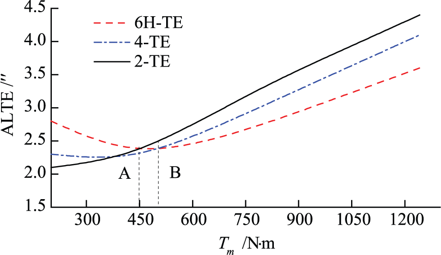
Comparison of ALTE under different loads.
From the simulation results in Figure 10, the corner impact force value of herringbone gear with 6H-TE is smaller than 4-TE and 2-TE under all load conditions, which is caused as a result of lowest load-carrying ratio at the initiation corner meshing point.
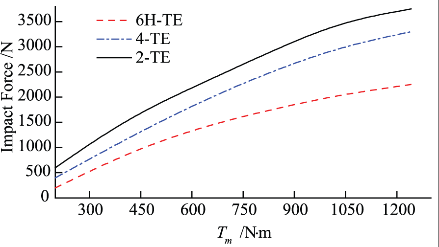
Comparison of corner impact force under different loads.
The simulation data from Figures 11–13 show that the vibration noise of herringbone gear with 6H-TE is obviously smaller than 4-TE and 2-TE under the given conditions. Under the conditions of 828 N·m and 2000 r/min, the RMS value of the herringbone gear meshing vibration with 6H-TE is 16.95 m/s2, and the corresponding values of 4-TE and 2-TE are 27.50 and 32.60 m/s2, respectively.

Comparison of vibration acceleration in time domain (828 N·m).

Comparison of vibration acceleration in frequency domain (828 N·m).
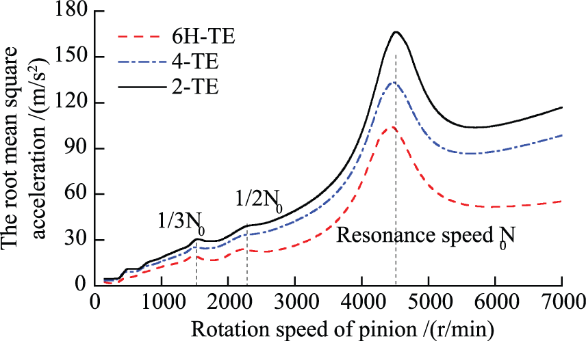
Comparison of vibration acceleration under different rotational speeds (828 N·m).
When the load value is less than 290 N·m (point C) in Figure 14, the RMS value of the herringbone gear meshing vibration with 6H-TE is bigger than 4-TE and 2-TE. With the load value rising to more than 312 N·m (point D in Figure 14), the vibration performance with 6H-TE is better than 4-TE and 2-TE. Point C and point D move toward the negative direction of the coordinate axis compared to points A and B in Figure 9 as the results of considering LTE and corner mesh impact force simultaneously.

Comparison of RMS under different incentive loads.
Conclusion
This article has provided a series of appropriate models to design and analyze the herringbone gear system with sixth-order transmission error based on meshing vibration optimization. The excitations of herringbone gear vibration model include varying-time meshing stiffness and corner meshing impact force. The polynomial coefficients of higher order transmission error are identified by specifying an optimization goal of MVA minimization. An example set of analyses were performed to point various unique features of herringbone gear transmission system with 6H-TE, and from the computerized simulation and comparison of the 6H-TE with 2-TE and 4-TE, some conclusions can be drawn as follows:
The TCA, LTCA theory, and improved adaptive genetic algorithm are applied to optimize the design for the herringbone gear system with 6H-TE. Such a semi-analytical approach to the calculation of the global optimum solution proved to be computationally more efficient than conventional finite element techniques.
The performance of vibration reduction under the optimization of MVA is much better than the optimization of ALTE. So, when you start to design the parameters of 6H-TE, it is better to choose the RMS value of MVA as optimization objective for achieving the desired vibration performance and noise quality.
In the range of design conditions, the herringbone gear with 6H-TE has the best vibration stability. The values of ALTE, corner meshing impact force, and MVA with 6H-TE are all lower than that with 4-TE and 2-TE. What draws more of our attention is that the values of ALTE and MVA with 6H-TE are bigger than with 4-TE and 2-TE in the low load range (under 300 N·m), that is to say, all design and optimization must be in the specified load range.
Footnotes
Academic Editor: Hamid Reza Karimi
Declaration of conflicting interests
The author(s) declared no potential conflicts of interest with respect to the research, authorship, and/or publication of this article.
Funding
The author(s) disclosed receipt of the following financial support for the research, authorship, and/or publication of this article: This work was supported by the China Postdoctoral Science Foundation (no. 2017M611710); Jiangsu 333 Project (no. BRA2016445); Priority Academic Program Development (PAPD) of Jiangsu Higher Education Institutions of China.