
Abstract
In view of the problem that local temperature of the original cylinder head is on the high side, an innovative cooling air duct is proposed. The cooling air duct introduces cool air into the cylinder head to forcedly cool the cylinder head, and multiple guide plates are set to distribute the cold air in the duct. The three-dimensional numerical simulation technology is adopted to analyze the impact of the air duct on the heat dissipation of cylinder head. Finally, the enhanced heat transfer characteristics of improvement schemes were evaluated. Results show that the high temperature of the improvement schemes effectively decreased and the cooling performance of the whole cylinder head and the final improvement scheme are enhanced. The highest temperature of the cylinder head in the final improvement scheme decreased by 28 K, and the average temperature of the intake duct in the final improvement scheme dropped by 12.8 K compared with that in the original cylinder head, which is conducive to increasing the intake density and the discharge coefficient.
Introduction
Heat load is an important factor affecting the reliability and durability of the engine; too high temperature of the engine cylinder head will lead to heating crack, ablation, creep deformation of the cylinder head, a sharp decline in the hardness and strength of the materials and the destruction, coking, and other problems of lubrication oil film,1,2 and it will also increase fuel consumption, and CO and HC emissions.3–5
For the cooling of the water-cooled engine, the difficulty lies in the efficient allocation of the coolant flow between different regions. In general, water diversion holes and various flow-guided structures are adopted to distribute the coolant flow.6,7 For the cooling of the air-cooled engine, due to the small heat transfer coefficient, the research focuses on how to increase the heat transfer surface area to strengthen the cooling of the engine;8,9 generally, the fin is set on the solid surface to enhance the heat transfer.
For the heat dissipation of air-cooled cylinder head, the heat dissipation is affected by the interaction between cold air and cylinder head, so the previous simulation with respect to the heat transfer of the engine cylinder head and cold air cannot reasonably analyze the heat transfer relationship between the cylinder head and the cold air. 10 In recent years, the newly developed simulation method can effectively solve the coupling heat transfer between the cylinder head and the cold air. This method combines the heat transfer processes in fluid and solid regions into a unified heat transfer process to find a solution, that is, the boundary conditions of the fluid–solid interface are transformed into the interior coupling boundary for calculation, which makes the simulation more realistic.11–13
In view of the problem that local temperature of the original cylinder head is on the high side, an innovative cooling air duct structure is put forward, and the cooling air duct introduces the cold air into the cylinder head to cooling the cylinder head forcedly. In addition, multiple guide plates are adopted to reasonably distribute the cold air inside the air duct. The numerical simulation technology is used to analyze the impact of the cooling air duct structure on the cooling performance of cylinder head. Then, the enhanced heat transfer characteristics of improvement schemes are evaluated. Finally, the optimal improved scheme is put forward.
Partial differential equation and its algorithm
Partial differential equation
The cold air flow near the cylinder head is turbulent. The flow and heat transfer processes comply with the mass conservation, momentum conservation, and energy conservation law. The heat transfer mechanism in the internal cylinder head is Fourier heat conduction law, which also satisfies the law of energy conservation. The form of energy control equation of the cylinder head is the same as that of the cold air, but the energy control equation has not convection terms. The steady-state control equation is as follows:
Mass conservation equation

Momentum conservation equation

Energy conservation equation

where
The standard

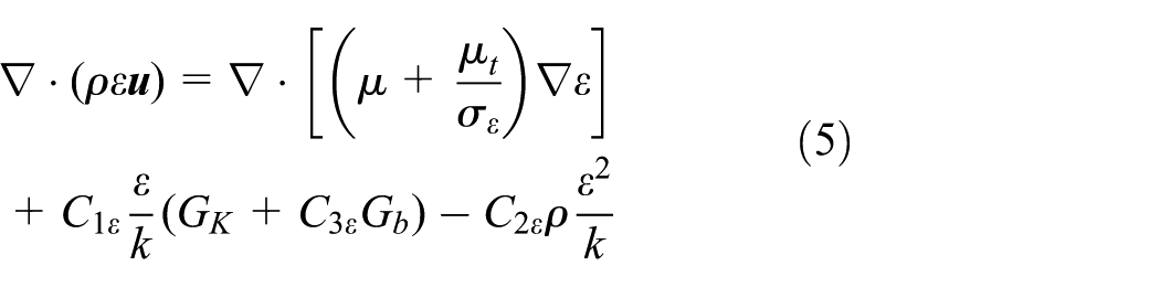
where
Dealing with the coupling boundary
This work adopts the fluid–solid coupling heat transfer simulation method to get the solution, which transformed the fluid–solid interface into the interior heat transfer coupling boundary. The interior heat transfer coupling boundary could meet the following conditions:
Continuous temperature of the coupling boundary

Continuous heat flow density of the coupling boundary

Third boundary condition on the coupling boundary

where subscript 1 is the solid region and subscript 2 is the fluid region.
At the fluid–solid interface, the standard wall function method is used to deal with the flow boundary layer and the heat transfer boundary layer. The wall function method is a set of semi-empirical formulas; the basic idea is as follows:
Simulation model of air-cooled engine cylinder head
The original engine is a single-cylinder four-stroke engine, with the cylinder diameter of 58.7 mm, the stroke of 55.5 mm, the rated power of 9.3 KW, the maximum pressure of 3.9 MPa, and the total volume of the cylinder of 149 mL. The cylinder head is a two-valve single type. During the process of establishing the three-dimensional fluid–solid coupling heat transfer model, the cooling effect of car body on the heat dissipation of the engine cylinder is ignored, that is, cold air is only pressed by the cylinder head. The flow field is large enough to ensure the adiabatic conditions of the outer boundary of the flow field. The cold air velocity and heat load are kept constant in a steady-state condition. A grid irrelevant analysis is carried for this model; finally, when the grid size reduces to 2 mm and grid number increases to about 340,000, the simulation results basically remain unchanged as further dense mesh. Consequently, the grid is about 340,000. The model is shown in Figure 1.

Fluid–solid coupling model of air cooling gasoline engine.
In simulation, the working condition is 6500 r/min which has the largest heat load, the corresponding flow inlet velocity is 15.1 m/s, the outlet is outlet flow boundary, and the outer boundary of flow field has no slip-wall boundary condition with environment temperature. The fluid–solid interface is the internal coupling boundary. To obtain the heat transfer coefficient and the temperature of the gas in combustion chamber, the zero-dimensional combustion model is adopted to simulate the working process of the engine. 15 Here, the zero-dimensional simulation is carried out by AVL Boost. Then, the instantaneous heat transfer coefficient and the temperature of the gas in combustion chamber are converted into the mean efficient heat transfer coefficient and mean efficient heat transfer gas temperature for steady multi-dimensional simulation by formulas (9) and (10), and the value here is the average in space. Figure 2 is the instantaneous temperature and heat transfer coefficient of the combustion surface in combustion chamber, and the surface of intake and exhaust port. The mean efficient temperature of the gas on combustion surface at the bottom of the cylinder head is 1215 K, and the mean efficient heat transfer coefficient is 514 W/(m2·K). Inside the exhaust port, the mean efficient gas temperature is 1085 K, and the mean efficient heat transfer coefficient is 344 W/(m2·K). In the intake port, the mean efficient gas temperature is 329 K and the mean efficient heat transfer coefficient is 392 W/(m2·K). The rest of the boundary is processed into adiabatic conditions. The SIMPLE algorithm is adopted to solve the model. The simulation is carried out by Fluent


Gas temperature and heat transfer coefficient on exhaust port (6500 r/min).
Experimental verification
Experimental bench and temperature measuring equipment
Figure 3 is the experimental test platform; the experiment platform is mainly composed of a Doppler infrared thermal imager, the dynamometer, the speed sensor, the control unit, the engine, and the blower.

Experimental bench.
The experimental temperature measurement adopts Doppler far infrared thermal imaging system; the Doppler far infrared thermal imager is composed of two basic parts: the optical device and the detector.16–18 Any object will issue infrared radiation to the outside as long as the temperature is higher than absolute zero. The optical device will focus on the infrared radiation emitted by the object onto the detector, and then, the detector converts the incident radiation energy into electrical signals, which, finally, is processed into a thermograph. According to the physical law between the radiation and the temperature, the higher the temperature, the larger the radiated energy, so the thermograph corresponds to the temperature of the surface.
Compared to the traditional thermocouple measurement, thermal imager measurement has continuous temperature data. Its thermograph is intuitive, and its no-contact measurement has the advantages of less human intervention, and convenient and quick measurement. The thermal imager used in the experiment is Type Fluke Ti10. The parameters are as follows: the temperature range is 253–523 K, the accuracy is 2%, the type of infrared detector is the focal plane array, uncooled micro-radiometer, the resolution of the infrared pixel is 160 × 120, thermal sensitivity is less than or equal to 0.1 K, the infrared band is 7.5–14 µm, and the resolution of the visible light camera is 640 × 480.
In order to obtain accurate measurement results in test, the following requirements should be paid attention: (1) focal length should be adjusted to reduce or eliminate other clutter heat reflection from background objects; (2) temperature measurement range should be adjusted to obtain the best image quality, which also could influence the measurement accuracy; and (3) the equipment must be kept stable during measurement in order to obtain clear image.
A blower is used to supply the air to cool the engine in test, and the air velocity depends on the operation conditions of the engine. When the blower is turned on, the speed and throttle of the engine are controlled by the control system, and the temperature is measured after the engine stably runs for about 1 h.
Figure 4 is the temperature distribution measured by Doppler thermal infrared imager in the cylinder head. As can be seen from this figure, the temperature distribution in the cylinder head could be intuitively and continuously observed, and the temperature of the exhaust gas is higher than that of the instrument range. The high-temperature region on the cylinder head surface is near the spark plug mounting hole and the exhaust duct, and the maximum temperature is up to about 496 K. The temperature drops from the exhaust side to the intake side and from the bottom to the top of the cylinder head, which agrees well with the simulation results.

Temperature contour of cylinder head.
As shown in Figure 5, to make further comparison between the simulation and experimental values, parts of the temperature data from horizontal and vertical lines in Figure 4 are collected to make the temperature curve. Neglecting the influence of the spark plug wires, the maximum error between simulation and experimental results is 6.6%. Both of them have the same temperature distribution trend. The temperature rises from the intake side to the exhaust side in the horizontal direction, and the region near the spark plug has the maximum value. While in the vertical direction, the temperature rises from the top to the bottom of the cylinder head.

Comparison between experiment and simulation.
Result analysis on original cylinder head and its problems
The high-temperature area of the original cylinder head mainly concentrates near the top of the combustion chamber and the exhaust port; the temperature in the high-temperature area at 6500 r/min is between 470 and 500 K, and the maximum temperature in the combustion surface is 501.8 K. The cylinder head adopts the material of aluminum alloy; when the temperature of the aluminum alloy is more than 473 K, the material intensity will decline. The maximum temperature difference between the intake port and exhaust port is 65 K, which will lead to a greater thermal stress. Detailed results are shown in Figure 10. In view of the above data, it is needed to improve the cooling system at the high-temperature area of the cylinder head.
Improvement of the cooling system of the cylinder head
Improvement schemes
Design principles
In view of the above problems, the improvement measures were put forward; the work creatively proposed to introduce a cold air duct in the cylinder head, and the cold air duct goes through the air windward side in the exhaust side to the inlet side of the cylinder head to cool the high-temperature areas by introducing the cold air into the cylinder head.
The following design requirements should be paid attention: (1) it is desirable to reasonably enlarge the air duct to introduce more cold air to cool the high-temperature region in cylinder head, (2) the duct surfaces should be kept smooth to reduce the flow resistance and avoid the generation of eddy, and (3) several air deflectors should be set to reasonably distribute the cooling air.
Design of the inlet and outlet cross-sectional shape of the air duct
Cross-sectional shape of the air duct inlet
Because the greater the cold air flow, the greater the heat dissipates of the cylinder head, flaring shape is adopted as the cross-sectional shape in the air duct inlet in order to increase the intake air. The inlet of the air duct is generally at the exhaust side of the cylinder head which should be cooled first due to its high temperature. To reduce the flow resistance, the angle between the entrance direction of air duct and the flow direction of cold air should be minimized as much as possible. Figure 6 is the cylinder head model with the air duct.

Structure of cylinder head with air duct.
As can be seen from Figures 6 and 7, compared to the air duct without the flaring inlet, the inlet air duct using flaring shape in this work has large intake area. Under the same intake pressure, the intake air will be greatly improved, which is conducive to the increase in the heat dissipation of the cylinder head.

Velocity distribution around cylinder head.
Design of the cross-sectional shape and position of the air duct outlet
The air duct outlet is near the spark plug, and the wall temperature near the spark plug is high, which should be cooled intensively. Therefore, the cross section of the air duct outlet should be lowered down to make lots of air flow through the high-temperature wall.
The size and position of the air duct outlet has great influence on the heat dissipation near the spark plug. The wall temperature of the exhaust side of cylinder head is higher than the air inlet side, so the position of the air duct outlet should be close to the exhaust side, and it could not only reduce the temperature of the exhaust side of the cylinder head but also reduce temperature difference between the exhaust side and the inlet side.
Design of two improved schemes
Improved scheme 1
To reduce the local high temperature near the top of the combustion chamber and exhaust passage of the original engine cylinder head, and to advisably cut down the temperature near the intake of the cylinder head to increase the intake air density and the intake air, an air duct is set in the lower part of the cylinder head. The air duct starts from the air windward side in the exhaust side and runs through the cylinder head, finally being exported from the air inlet side. It consists of three segments, the first segment at the exhaust side of the cylinder head, the connection segment in the middle part, and the third segment at the inlet side. Meanwhile, this air duct connects to the heat dissipation hole in central cylinder head, thus forming another air duct. For the first section air duct in the exhaust side, to introduce more cold air to cool the high-temperature region in cylinder head, the air duct should be properly enlarged. The entrance of the air duct adopts the flaring structure to introduce more cold air; the duct surfaces should be kept smooth to reduce the flow resistance. In the heat dissipation hole, a guide plate is set to distribute flow rationally.
Improved scheme 2
The analysis of improved scheme 1 indicates that the flow distribution is very unreasonable. Excessive cold air flows into the third segment of the air duct at the inlet side, which leads to barely satisfactory cooling effect of the high-temperature zone near the spark plug. Therefore, it is difficult and important to achieve the rational distribution of the flow in the connection segment of the air duct. Besides, the local flow resistance in the air duct is very large due to the large change angle of the cold air flow direction from the first section to the second section of the air duct. Consequently, it is needed to set up a special structure so that more cold air can enter the heat dissipation holes with small flow resistance. Therefore, based on the improved scheme 1, a guide plate is set inside the end of the first section of the air duct, and the guide plate and the cold air flow form a certain angle to distribute the flow between the third section of the air duct at the intake side and the heat dissipation hole. In addition, a larger arc was adopted as transition in the corner of the air duct to reduce local flow resistance. In the heat dissipation hole, three guide plates (one large and two small) are set: the large one plays the role of distributing the flow and the two small ones play the role of redistributing the flow in the smaller regions. Figure 8 shows the improved model of the cooling system of the cylinder head.
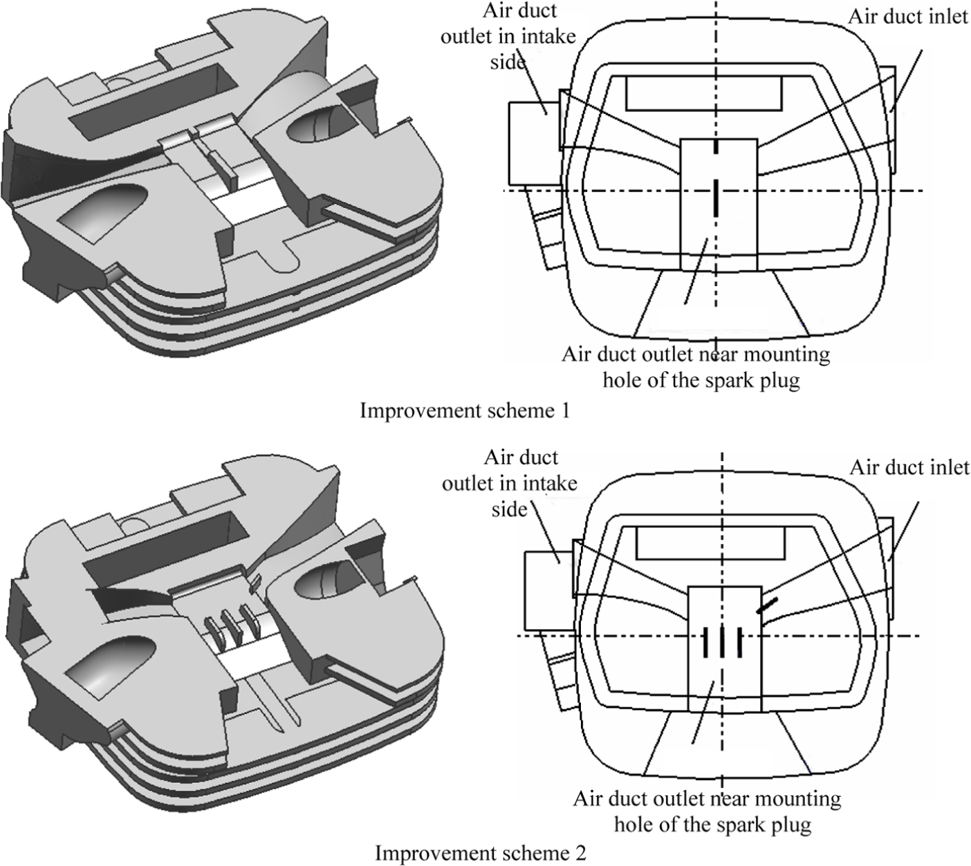
Structure of cylinder head of improvement scheme.
Discussions
The same boundary conditions are applied to the different schemes to analyze the fluid–solid coupling heat transfer characteristics. Figure 9 shows the flow distribution of the improved schemes, and Figure 10 shows the temperature distribution of different schemes.

Velocity distribution of the improvement schemes.

Temperature distribution of the improvement schemes.
In the improved scheme 1, the air flow velocity at the outlet of the heat dissipation hole is 15.6 m/s and the air flow velocity at the air duct outlet in intake side is 23.4 m/s. In the improved scheme 2, the air flow velocity at the outlet of the heat dissipation hole is 32.8 m/s and the air flow velocity at the air duct outlet in intake side is 15.7 m/s. Therefore, the air flow velocity at the outlet of the heat dissipation hole in improved scheme 1 is smaller than the one in improved scheme 2 in which the guide plates is adopted in the air duct to improve the air flow velocity and increase the flow in the heat dissipation hole. Meanwhile, three guide plates set in the heat dissipation hole improve the flow uniformity in the heat dissipation, thus improving the heat dissipation performance of the combustion surface and high-temperature zone around the exhaust duct.
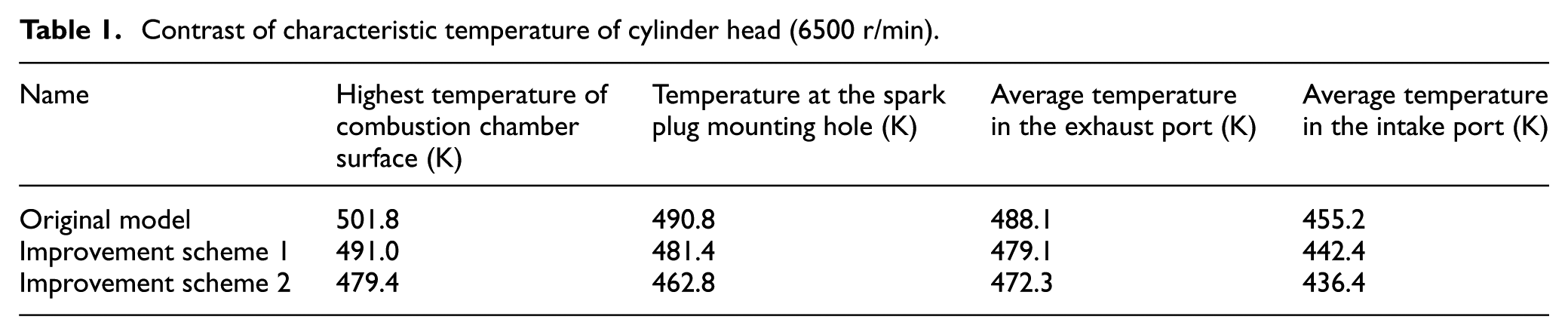
Figure 10 shows that the temperature in the high-temperature zone which needs to be cooled down is reduced in the improvement scheme. The highest of all temperatures appear in the heat dissipation hole close to the exhaust side of the cylinder head. The highest temperature on the original cylinder head surface is 490.8 K, and in scheme 1, it is reduced to 481.4 K, while in scheme 2, it is reduced to 462.8 K with the decrease of 28 K. This indicates that the cooling effect of the air duct is good and the method to use guide plate in the air duct to distribute flow is feasible. The average temperature of the cylinder head surface in these three schemes is 436.0, 430.5, and 426.4 K, respectively.
To conduct a comprehensive analysis of the enhanced heat dissipation effect of the improved schemes, Figure 10 shows the temperature distribution of the combustion chamber wall, intake duct wall, and exhaust passage wall in the cylinder head. As can be seen from the figure, temperature of all the regions has significant decrease compared to the original scheme. Table 1 shows the characteristic temperature value extracted from the temperature distribution profile. Compared to the original cylinder head, the maximum temperature of the combustion chamber wall is reduced by 10.8 K in the improved scheme 1, while in the improved scheme 2, it is reduced by 22.4 K. In the improved scheme 2, the average temperature of intake duct is reduced by 18.8 K compared to the original scheme, which is conducive to the increase in the intake density and discharge coefficient. Therefore, the enhanced cooling effect of air duct is obvious. Scheme 2 is the optimum scheme and it has achieved the desired effect.
Contrast of characteristic temperature of cylinder head (6500 r/min).
Conclusion
As the local temperature of the original cylinder head is on the high side, an innovative cooling air duct is proposed. The cooling air duct introduces cool air into the cylinder head to forcedly cool the cylinder head, and the multiple guide plates are set to distribute the cold air in the duct. Results show that the high temperature of improvement schemes effectively decreases and the highest temperature of cylinder head in the final improvement scheme decreased by 28 K.
In the final improved scheme, the cold air is introduced into the intake side of the cylinder head, which makes the average temperature of the intake duct drop by 12.8 K compared to that in the original cylinder head, which is conducive to increasing the intake density and the discharge coefficient.
The new simulation technology can reasonably simulate the coupling heat transfer relationship between the air-cooled engine cylinder head and the cold air. The simulation results are in agreement with the experimental results, and the maximum error is less than 7%.
Footnotes
Academic Editor: Jose Ramon Serrano
Declaration of conflicting interests
The author(s) declared no potential conflicts of interest with respect to the research, authorship, and/or publication of this article.
Funding
The author(s) disclosed receipt of the following financial support for the research, authorship, and/or publication of this article: This study was supported by the National Natural Science Foundation of China through grant no. 51175530; the Foundation and Advanced Research Program General Project of Chongqing City, China, through grant cstc2016jcyjA0499; and the Board of Education Science and Technology Research Project of Chongqing City, China, through grant no. KJ1705112.