
Abstract
Turbochargers are inherently dynamic devices, comprising internal flow volumes, mechanical inertias and thermal masses. When operating under transient conditions within an engine system, these dynamics need to be better understood. In this paper, a new non-dimensional modelling approach to characterise the turbocharger is proposed. Two new dimensionless quantities are defined with respect to mechanical and thermal transient behaviour, which are used in conjunction with the Strouhal number for flow transients. The modelling approach is applied to a small wastegated turbocharger and validated against experimental results. The model is used to simulate the turbocharger mass flow rate, turbine housing temperature and shaft speed responses to different excitation frequencies for different sizes of turbine. The results highlight the influence of turbocharger size on the dynamic behaviour of the system, which is particularly marked for the turbine housing temperature. At certain frequency ranges, the system behaviour is quasi-steady, allowing modelling through static maps in these operating regions. Outside these ranges, however, transient elements play a more important role. The simulation study shows that the proposed dimensionless parameters can be used to normalise the influence of turbine size on the dynamic response characteristics of the system. The model and corresponding dimensionless parameters can be applied in future simulation studies as well as for turbocharger matching in industry.
Keywords
Introduction
The turbocharger has an important role in engine downsizing. In practice, turbocharger performance depends on good matching between the turbomachinery and the engine itself. Turbocharger matching is commonly undertaken using one-dimensional (1D) engine codes in which the turbine and compressor behaviour are assumed to be quasi-steady. The models are essentially look-up tables or maps derived from steady flow gas-stand data.
In reality, however, flow conditions are highly transient on-engine, with the turbine typically operating under unsteady conditions rather than the design states, making the turbocharger performance prediction challenging. 1 The pulsating character of the system due to the reciprocating movement of the piston and opening and closure of the valves is a major underlying cause of the unsteady behaviour of the flow.2,3
Both 1D and 3D methodologies have been used to analyse turbocharger transient performance, complemented by specialist experimental techniques to capture and measure performance characteristics under these conditions. In the research of Benson 4 and Wallace and colleagues,5,6 deviations were found by using quasi-steady models to predict turbine averaged performance under unsteady flow. The results of Kosuge et al. 7 indicate that when the turbine is subjected to unsteady flow conditions, averaged mass flow and power are under-estimated under the quasi-steady assumption. Similar results were also found using a CFD simulation method. 8
Further investigations have broken down the turbine element and shown that the impeller performance can be approximated to quasi-steady models,9–12 but the accumulation of mass in-volute cannot.8,13 Similar dynamic characteristics have been observed for wastegated, variable-geometry and multi-entry turbines.14–18 Though specialist facilities are being proposed to better measure the transient performance of turbochargers under pulsating conditions, these are often limited by measurement capabilities. 19
A number of studies have attempted to quantify the importance of unsteady effects on turbine performance. The research of Kosuge et al. 7 and Capobianco and colleagues20,21 noted that the amplitude of pulsation flow imposed on the turbine is the main factor determining the validity of the quasi-steady assumption. For fluid mechanics, the degree of influence of unsteady flow is reflected by the Strouhal number.1,22 Research by Costall et al.9,10 has highlighted that an increase in pulse frequency and, hence, the Strouhal number will result in a large difference between the steady and unsteady performances of the turbine. These findings show a strong connection between the Strouhal number and unsteady effects. Therefore, in subsequent research, the Strouhal number has been used as a criterion by which to predict the onset of unsteadiness.9,10,22
Furthermore, modelling turbochargers presents a multi-frequency problem since the device is excited by both high-frequency stimuli due to the operation of the exhaust valves and low-frequency excitations resulting from changes in engine speed, load and thermal state.23,24 Indeed, in previous research, it is shown that the behaviour of three main physical dynamic aspects is distributed over a wide-frequency spectrum. 25 In the very-low-frequency range (from 0.001 to 0.05 Hz), thermodynamics play the main role in turbocharger transient performance, 26 while mechanical aspects play a more dominant role in frequency regions from 0.1 to 50 Hz. 27 By way of contrast, the gas dynamics response to exhaust pulsating flow formed by the operation of an exhaust valve occurs in the region between 50 and 200 Hz.
In addition, the size of the turbomachinery itself can influence the magnitudes of turbine flow rate and, in turn, the dynamic response of different aspects of the system such as temperature and turbine speed. For example, for a given engine operating condition, the greater the mass of the turbocharger, the higher its thermal inertia will be and, therefore, the slower its temperature will change in response to a change in exhaust gas enthalpy. Similarly, for a given turbocharger size, a larger change in exhaust enthalpy will cause a more rapid change in temperature. The transient response is hence a balance between the system size and the magnitude of the excitations.
Non-dimensional analysis offers a way of generalising this type of problem, and it is the hypothesis of this paper that a non-dimensional method could be used as a new modelling approach for turbochargers, allowing a direct comparison between devices of different sizes. Indeed, the dependence on size has been approached in turbine design by the use of non-dimensional parameters.28,29 Most analysis has hitherto focussed on understanding and characterising the high-frequency dynamics associated with mass accumulation in the volute. This is because the air dynamics is an important factor that restricts the use of quasi-steady models in turbocharger operation under unsteady boundary conditions.
Generally, turbocharger maps can be scaled from one turbocharger size to another based on similarity laws.30–34 In view of geometric similarity, the corresponding dimensions of the machines are approximately proportional to each other. With similar dynamics, the forces and velocities developed at the corresponding local points are parallel and proportional. This means that the same dimensionless parameters are applicable for similarly designed but differently sized machines. 34
Previous research has shown the utility of the Reynolds and Strouhal numbers in modelling and predicting flow and performance.35,36 However, although the influence of the Reynolds number on pressure is small, 37 the effects on efficiency can be significant.38,39 In order to address efficiency problems, Ernst et al. 40 propose an empirical method for a centrifugal compressor.
Furthermore, Dufour et al. 41 suggest that with a speed multiplier that is the square root of the mass flow rate change produces better results in centrifugal compressor scaling when implementing similarity laws. Copeland et al. argue that only the frequency influence is considered by using the Strouhal number to quantify the unsteadiness of turbine performance. 42 Since the amplitude of pulse flows is also critical, 22 a modified parameter that is a combination of the Strouhal number and a dimensionless amplitude factor was introduced to evaluate the performance of turbine volute and turbine rotor. 42
While past research has focussed on dimensional analysis for investigating the inherent turbocharger dynamics excited by pulsating engine exhaust flow, no investigations have thus far been proposed regarding dimensionless parameters for the other fundamental dynamics including the thermal and mechanical elements of the turbomachinery. Goumy et al. 43 have sought to correlate heat transfer characteristics with rotor wheel sizes. This is a first step towards a dimensionless coefficient for the thermal behaviour.
Hence, in this research, dimensionless parameters that can generalise the transient response are proposed. The aim of this paper is thus to evaluate the dynamic response of automotive turbochargers across a range of turbine sizes and to assess the utility of the proposed dimensionless parameters as a modelling tool.
Methods
Turbocharger modelling
A physics-based, dynamic model of the turbocharger turbine is used in this research. Figure 1 shows the main structure of the model, which was developed in 1D gas dynamics environment GT-POWER (Gamma Technologies, LLC, Westmont, IL, USA). The tongue, volute, stator, rotor and diffuser are represented by a series of ducts and orifices. The diameter and flow coefficients of these orifices are varied to represent the flow characteristics of the turbocharger. The diameter and flow coefficient of the orifices connecting the volute and the inter-volume and between the inter-volume and the diffuser are varied depending on the operating speed and pressure ratio of the turbine. It can be seen that sinusoidal excitations can be applied at the turbine inlet boundary and to the wastegate (WG) actuator model to elicit a transient response from the model.
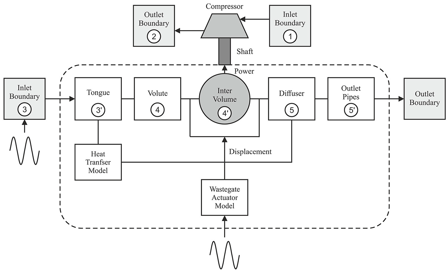
Overview of the turbocharger model.
The turbine work

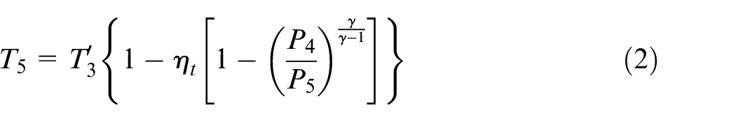
The temperature at point 5 is given via the equation for isentropic expansion and the turbine efficiency
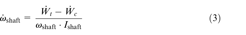
The rotational speed of the shaft
The WG was actuated by a pneumatic actuator driven by a vacuum and is shown schematically with the linkage mechanism in Figure 2. The WG pivots as depicted in the figure to angle
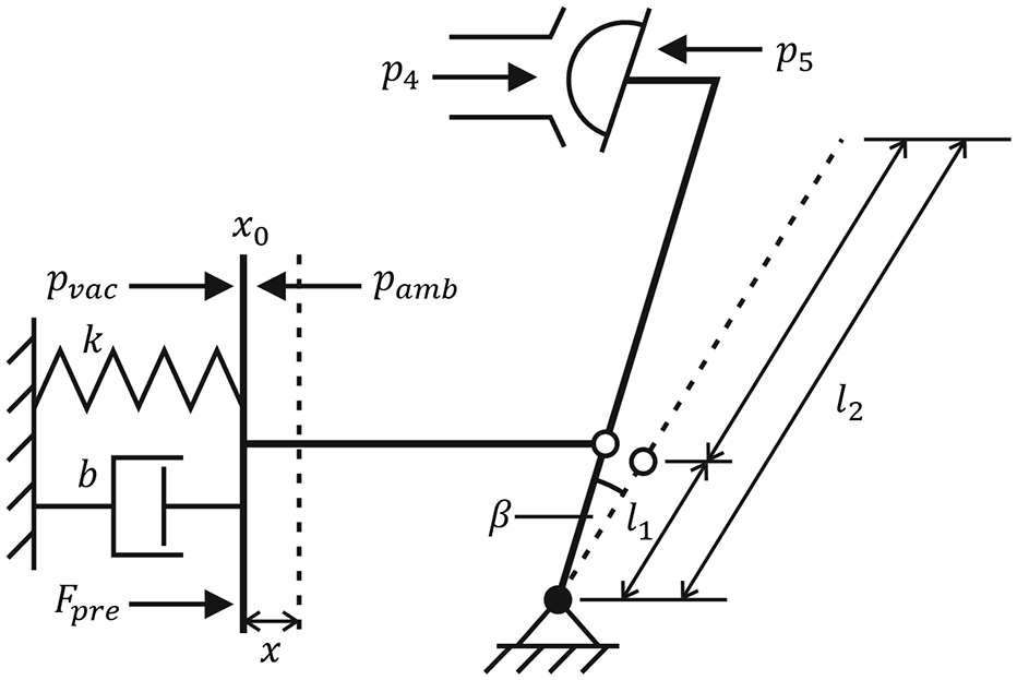
Wastegate actuator model.
Inside the actuator, a spring of stiffness
Applying Newton’s second law to the rotation of the WG pivot yields equation (4), which governs the dynamics of the WG actuator. The inertia of the system
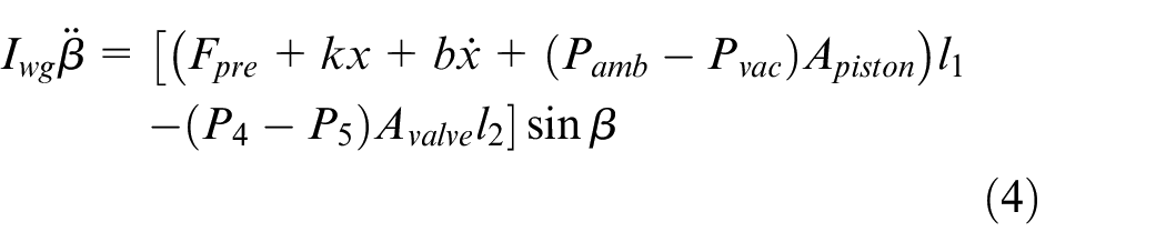
The input to the actuator model is the vacuum pressure
In addition to the thermodynamic and WG sub-models, a lumped capacitance heat transfer model is incorporated in the simulation environment. Finally, the overall physical model is then scaled to simulate turbochargers of different sizes.
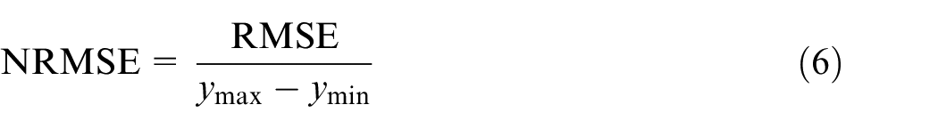
The accuracy of the turbocharger model is assessed using the normalised root-mean-square error (NRMSE) metric. This is evaluated by first calculating the root-mean-square error (RMSE) using the difference between the experimental data value
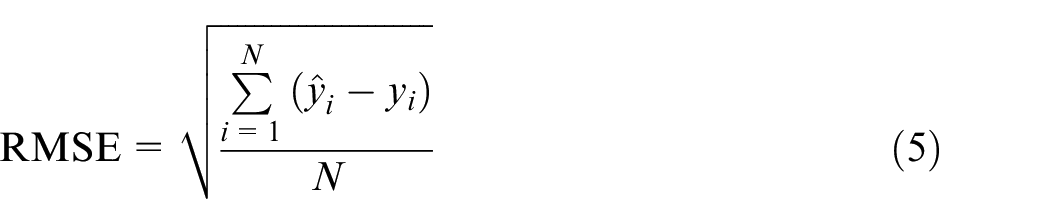
As shown in equation (6), this value is then normalised by the data range, which is the difference between the maximum and minimum values of the data, denoted here as
Model validation
The model has previously been validated under steady flow conditions. 25 To further extend this research, transient validation is performed here on a dedicated turbocharger test facility, which is depicted in Figure 3 and is built around a 2.2 L diesel engine.
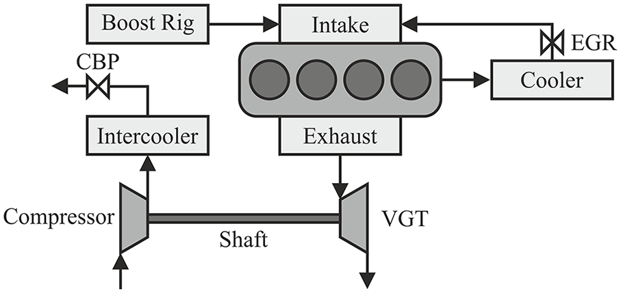
Illustration of the test rig used for model validation.
The test rig allows the intake boundary conditions including pressure, temperature and mass flow rate of an engine to be regulated as desired. As Figure 3 shows, the compressor outlet boundary can be controlled by operating the back-pressure valve located in the compressor downstream air passage. In the tests, the exhaust gas recirculation circuit of the engine was closed to avoid measurement errors in the engine intake mass flow.
The mass flow rate was measured using two sensors placed at the inlet of the compressor and the engine intake. Since the mass flow sensors are sensitive to temperature variations, the mass flow rate of the turbine cannot be measured directly. Hence, the value was calculated via the sum of the intake mass flow rate and the fuel consumption rate of the engine. Several pressure sensors (Type 4049, Kistler Holding AG, Winterthur, Switzerland) were placed at the engine exhaust manifold and the turbocharger inlet to obtain instantaneous pressure pulsation data for the engine exhaust and turbine inlet flows.
Dimensionless parameters
As previously noted, different turbine sizes will have different dynamic responses. Therefore, if the transient performance of differently sized turbines is characterised against the same excitation frequency, different responses will be expected across the various turbines. Moreover, the physical dimensions of the turbomachinery will play an important role in determining the critical-frequency regions for key dynamic parameters under different operating scenarios.
In fluid dynamics, the Strouhal number, given in equation (7), is a dimensionless parameter that represents a measure of the ratio of the inertial forces due to the unsteadiness of the flow and local acceleration to the inertial forces due to changes in velocity from one point to another in the flow field. In this equation,
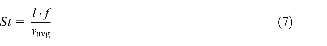
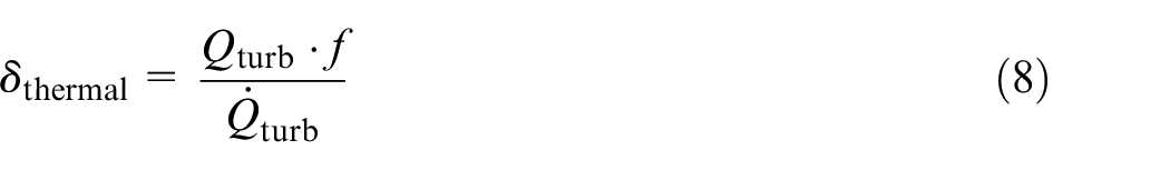
The Strouhal number is used for dimensionless quantification of the flow response at excitation frequencies between 5 and 300 Hz. Following a similar approach, two dimensionless parameters, shown in equations (8) and (9) for thermodynamics and mechanical dynamics, are proposed in this paper.
Equation (8) shows the thermal dimensionless parameter
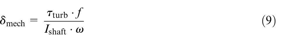
Equation (9) shows the dimensionless mechanical parameter
Simulation study of dimensionless parameters
Elicitation of frequency response data
The model developed in section ‘Turbocharger modelling’ is used to investigate the derived dimensionless parameters for different turbine sizes. Boundary conditions were set so as to excite the systems at different frequencies. For each aspect, the frequency range has been determined based on previous research, 25 with the frequency ranges being summarised in Table 1.
Frequency ranges of interest for different factors.
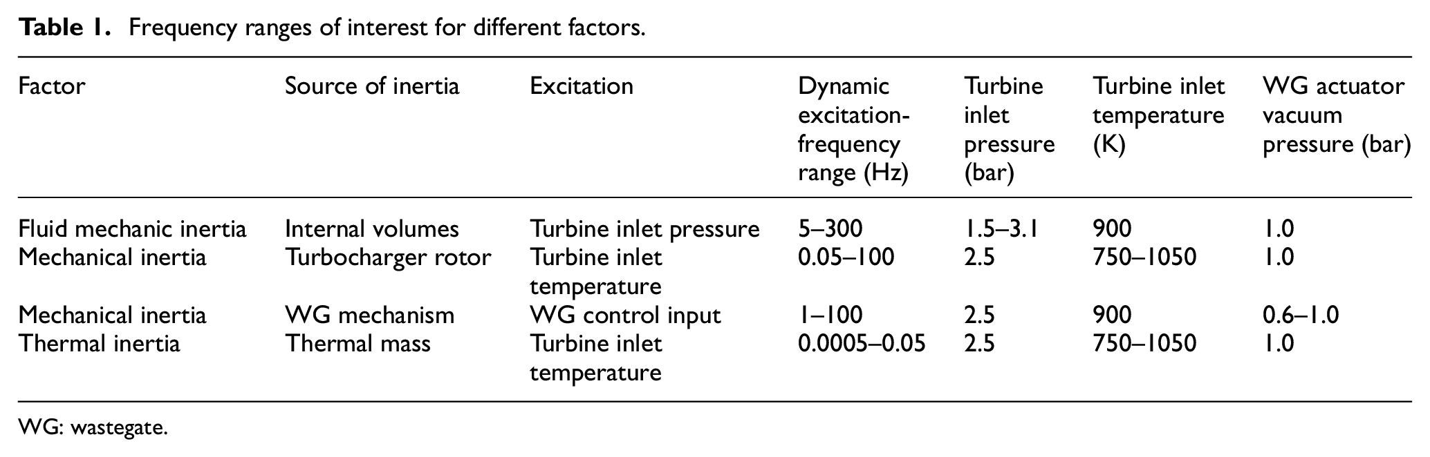
WG: wastegate.
The dynamic response is obtained by exciting the variables listed in Table 1 with pure sinewaves spanning the listed frequencies. The inputs were varied as follows:
Turbine intake temperature was varied between 750 and 1050 K;
Turbine intake pressure was varied between 1.5 and 3.1 bar;
WG vacuum pressure was varied 0.6–1 bar.
Only one factor was varied to create the excitations, with the others being held constant as defined in Table 1. In previous research by Deng et al., 25 these turbine inlet boundary conditions were varied simultaneously. The results showed that the dynamic response of the three aspects presented the same characteristics for all boundary conditions throughout the frequency spectrum. Therefore, in this paper, only one is varied for any given experiment.
Four sizes of turbochargers are considered in the simulation study: 0.8, 1, 1.4 and 1.8. The turbocharger size index is determined by normalising the maximum flow rate of each individual device by the maximum mass flow rate of one particular turbine.
On the compressor side, the inlet boundary temperature is set at 298 K and the pressure at 1 bar. Regarding the outlet boundary conditions, one orifice with a smaller diameter than the other pipes located in the compressor downstream air path is used to develop back-pressure for the compressor.
The various outputs of the turbomachinery – mass flow rates, temperatures and turbocharger speed – have been normalised due to commercial confidentiality. The normalisation is arbitrarily performed for each variable by taking the maximum value of that variable observed during the tests of one of the individual turbochargers and subsequently using that number as a divisor for that response variable across all turbine sizes.
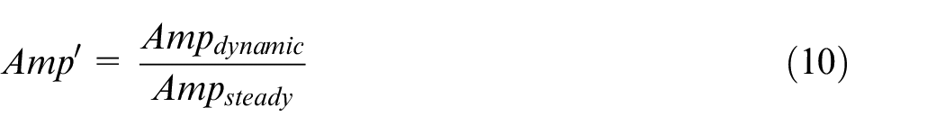
Application of dimensionless parameters
The resulting frequency data obtained enable the various dynamic response variables such as the housing temperature and turbocharger speed to be plotted against the proposed dimensionless parameters, which in turn depend on the excitation frequency. This is performed for the four different turbine sizes to investigate the extent to which the dimensionless parameters can reduce the influence of turbine speed on the dynamic response, thus allowing generalisation of the model across different turbine sizes.
Results and discussion
Model validation
Figure 4 compares the turbine inlet pressure as predicted by the model and that produced during the validation tests. Four different engine speeds at different engine loads were considered. The normalised RMSEs between the experimental and simulated values are summarised in Table 2. It can be observed that the turbine dual orifice model represents the actual pulsating flow well.
Normalised root-mean-square errors for the turbine inlet pressure modelling results.
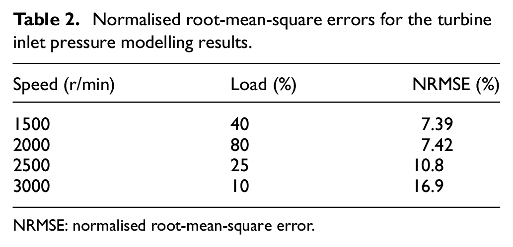
NRMSE: normalised root-mean-square error.
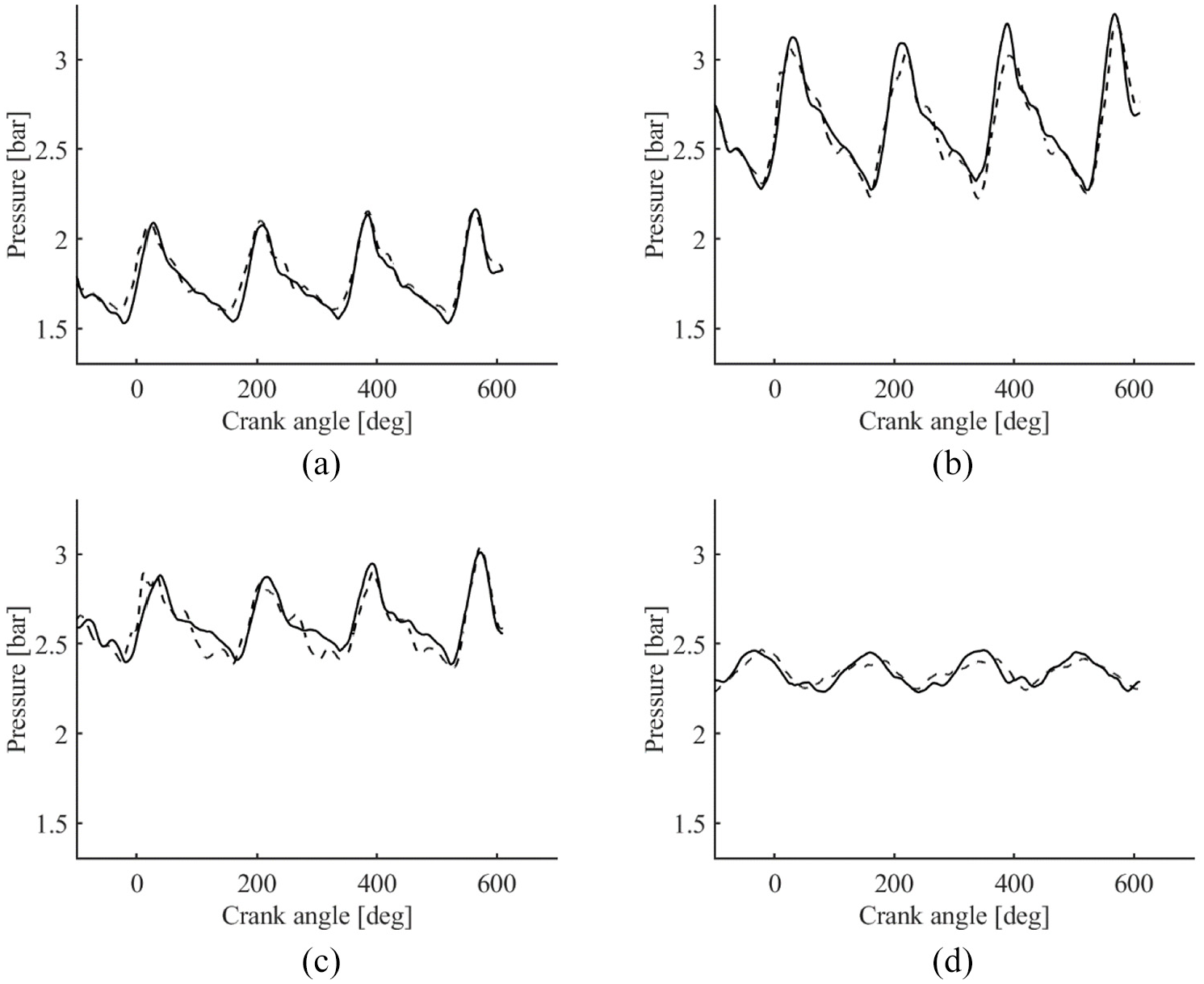
Comparison of modelling and experimental turbine inlet pressures, with solid and dashed lines, respectively, representing test and simulation data: (a) 1500 r/min at 40% load; (b) 2000 r/min at 80% load; (c) 2500 r/min at 25% load; and (d) 3000 r/min at 10% load.
The behaviour of the WG actuator at engine speeds of 2000 and 3000 r/min, where the pressure in the vacuum chamber was constant, is depicted in Figure 5. Table 3 shows the NRMSEs for the WG displacement model. Again, a good agreement is achieved between simulation and test results, indicating accurate assumed values for the system inertia and air dynamics aspects of the model.
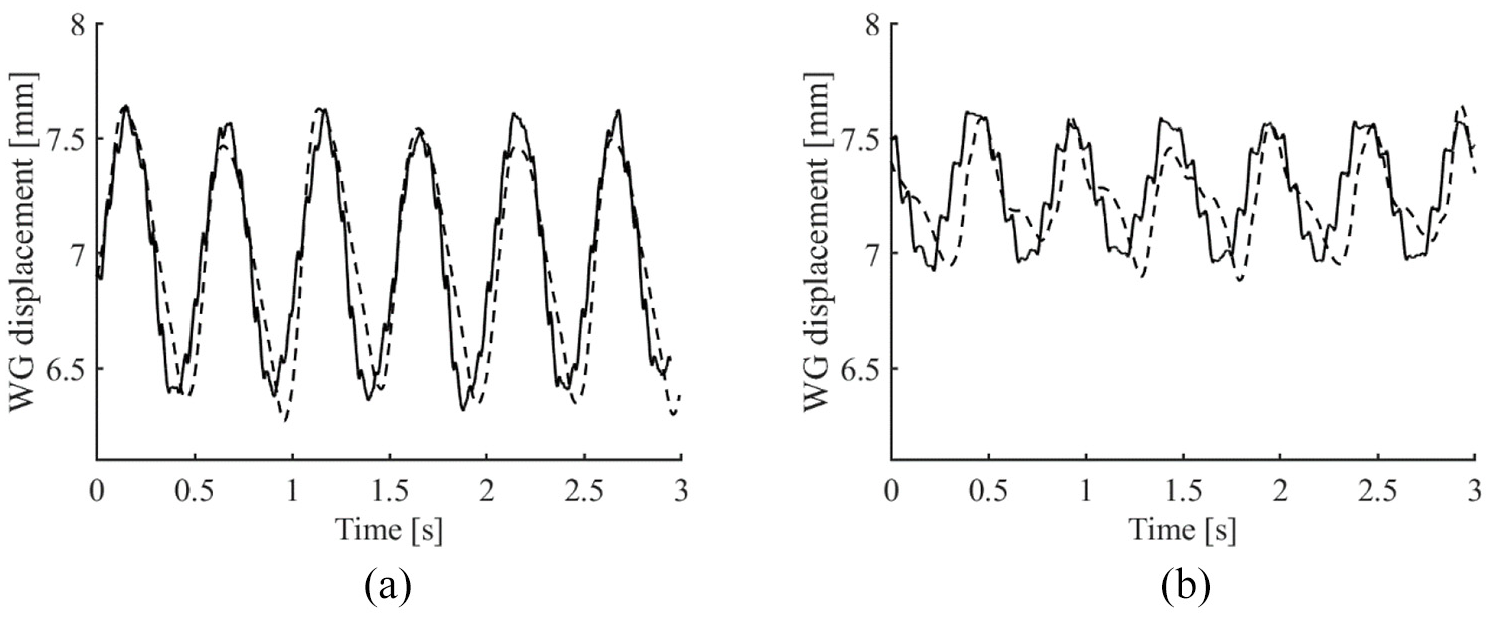
Comparison of modelling and experimental wastegate displacement pressures, with solid and dashed lines, respectively, representing test and simulation data: (a) displacement at 2000 r/min and (b) displacement at 3000 r/min.
Normalised root-mean-square errors for the wastegate displacement modelling results.
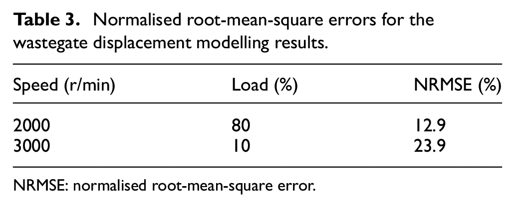
NRMSE: normalised root-mean-square error.
Simulation study
Figure 6 shows the results for the normalised mass flow, housing temperature and turbocharger speed and WG position. The results were generated by imposing sinusoidal dynamic boundary conditions at the specified frequency. The

Normalised dynamic response data at different excitation frequencies, with the different turbine sizes being shown in the legend: (a) normalised mass flow rate in the volute, (b) normalised turbine housing temperature, (c) normalised turbocharger speed and (d) normalised wastegate.
Figure 6(a) presents the amplitude ratio for mass flow rate in the volute. Twenty-four boundary conditions with different frequencies were imposed on the turbine from 10 to 300 Hz. The results show that the mass flow rate amplitude increases within a frequency range from 50 to 160 Hz, while the amplitude decreases with further frequency increases.
The response is similar for all turbocharger sizes, suggesting that the size of the turbocharger has little impact on the dynamic response. The key difference between sizes is obvious only for frequencies above 60 Hz. This implies that at the lower frequencies, the response is dominated by elements outside the turbocharger which make up the total system volume. The shape of the graph is broadly in line with that proposed by Copeland et al. 42 However, a major difference is the decrease in amplitude at 300 Hz, which occurs because higher-frequency aspects stemming from flow effects of blade-passing and turbulence are not simulated within the proposed model.
Figure 6(b) shows the change in turbine housing temperature in response to changes in turbine inlet temperature. Fifteen test cases with frequencies from 0.0005 to 0.1 Hz were simulated for each turbocharger size. With varying turbocharger size, the mass of turbine and compressor housing changes, resulting in different thermal inertias since larger turbochargers are encased in the heavier turbocharger. Therefore, a larger turbocharger requires more time to achieve the temperature change for a given set of boundary conditions. As Figure 6(b) shows, the amplitude decreases considerably for larger turbochargers. Moreover, as the turbocharger size decreases, the assumption of quasi-steady behaviour can hold at progressively lower frequencies.
Similar phenomena were also found for turbocharger shaft speed performance. In Figure 6(c), 25 test points were obtained for frequencies varied from 0.05 to 120 Hz. Compared with the turbine housing temperature, the influence of turbocharger size on the shaft dynamic response is more moderate. This shows that the effect of mechanical inertia of the turbocharger shaft is concentrated over a smaller-frequency range than that of the thermal inertia. However, the frequency range over this dynamic behaviour is strongest around 1–10 Hz, which coincides with the key range of the engine torque response, illustrating why the mechanical inertia of the turbocharger shaft has been and remains a key parameter in 1D engine simulation codes.
Figure 6(d) shows the normalised WG actuator amplitude against frequency. The response is similar for all turbocharger sizes, showing that the quasi-steady assumption will hold up to a frequency of around 3 Hz. This is interesting as it is often a parameter that is ignored within 1D engine simulation codes. The WG mechanical inertia does not vary significantly between turbochargers, and consequently, there is little difference between the turbocharger sizes. For this reason, it was decided not to propose a dimensionless parameter for the WG system.
Non-dimensional parameters
The results presented in Figure 6 point to significant differences between the dynamic response for a given set of boundary conditions as the turbocharger size is varied. This is problematic in the case of 1D engine modelling as it means that specific values relating to the housing and mechanical inertia are required. Hence, it is proposed to reprocess the data as a function of the non-dimensional parameters proposed in equations (8) and (9).
Figure 7 depicts different aspects of the dynamic response in relation to the dimensionless parameters. Figure 7(a) shows the amplitude in flow response as a function of the Strouhal number. When considering Figure 6(a), there was already a close agreement between the different turbocharger sizes at frequencies below 60 Hz. The use of the Strouhal number to compare across the turbocharger sizes has collapsed the response onto a single line in the region of the Strouhal number 0.07–0.15.
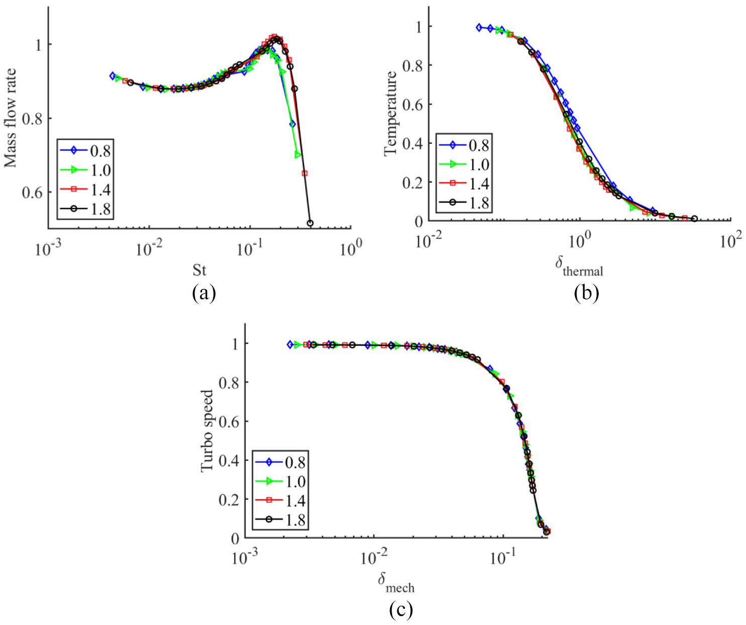
Prediction of speed and temperature responses using dimensionless parameters, with the different turbine sizes being shown in the legend: (a) normalised mass flow rate in the turbine volute, (b) turbine housing temperature response and (c) turbocharger speed response.
Figure 7(b) shows the amplitude response of the housing temperature as a function of the dimensionless thermal parameter
Figure 7(c) shows the amplitude response for turbocharger speed against the dimensionless mechanical parameter. As with the housing temperature, comparing Figure 7(c) to Figure 6(c) reveals that the dimensionless parameter captures the effect of turbocharger size on the rotational speed response, with all the curves having again collapsed onto a single line. The results show that for parameter values below 0.01, the quasi-steady assumption will hold. Here, the critical dynamic range is for values between 0.01 and 0.2, and there is no response for values below 0.03. As for the thermal case, evaluating the dimensionless mechanical parameter for a simulation task will allow the importance of the accuracy of shaft mechanical inertia to be determined.
The introduction of dimensionless parameters for the mechanical and thermal dynamics greatly reduces the influence of the turbocharger size on key dynamic response characteristics. Past research has focussed on the application of dimensional analysis for the turbocharger dynamics excited by the pulsating engine exhaust flow in response to the interest on the part of industry in turbocharger matching for peak power and torque, where the thermal and mechanical transients have limited importance. However, with an increased vehicle legislation focus on real driving conditions, other elements such as load transients, low load and warm-up will become important operating conditions to include in engine simulations.
In this paper, different sizes of turbocharger are considered. It is also assumed that all these turbochargers are similar machines with the same trim method and same geometric ratios. Hence, it is assumed that the corresponding dimensions of the turbochargers are proportional to each other and that the forces and velocities at the corresponding local points are parallel and proportional as well. However, in practice, this may be difficult for turbocharger manufacturers to achieve exactly.
Conclusion
A turbocharger simulation platform has been developed to investigate the application of dimensional analysis to turbine performance. The model has been validated against experimental data by means of a bespoke test facility, with close agreement being shown between the simulated results and real data. Two dimensionless parameters are proposed for the thermal and mechanical response characteristics of the turbine. The simulation results confirm that the dimensionless parameters reduce the influence of the turbine size on the mechanical and thermal responses of the turbocharger system, providing an effective modelling tool for industrial and research applications.
The flow response was similar for all turbochargers at frequencies below 60 Hz, suggesting the response at these frequencies is dominated by the wider system volumes. This corresponds to pulsations that would be generated from a three-cylinder, four-stroke engine at 2400 r/min, which highlights the importance of the internal volumes for on-engine operation. The WG response is similar across turbo sizes as inertia does not vary significantly with turbocharger size within the tested ranges. Interestingly, the dynamic response could be important from a frequency of 3 Hz. This frequency is well below that of the exhaust pulsations, but it is important for engine transient response during load steps, which typically occur over periods of 1–3 s. This may mean that neglecting it, as typically performed in typical engine transient performance calculations, may lead to significant errors. Though the thermal and shaft speed responses are dependent on turbocharger size, they can be accounted for via the proposed dimensionless parameters. The results show how evaluating these parameters can help identify how critical the mechanical or thermal models are for the overall behaviour of the turbocharger.
The proposed new metrics demonstrate that dimensionless numbers can be used to capture the changes in turbine and turbocharger transient responses as size is varied. This is particularly useful during the early phases of engine turbine matching, as it could be incorporated into 1D modelling tools to allow a simple scaling functionality that would go beyond traditional mass flow multipliers. The introduction of these continuous and scalable models is a critical step towards allowing mathematical optimisation to be used for boosting system design. This will allow early insights into the design trade-offs affecting aftertreatment light-off, efficiency and transient response.
Footnotes
Declaration of conflicting interests
The author(s) declared no potential conflicts of interest with respect to the research, authorship and/or publication of this article.
Funding
The author(s) received no financial support for the research, authorship and/or publication of this article.