
Abstract
Screw axial-flow pumps, with three different tip clearance values (RTC = 1, 2, and 3 mm), were respectively investigated to analyze the influence of key parameters on external characteristics and cavitation performance. The simulation results were in good agreement with the experimental values. The results showed that the external characteristics and cavitation performance of the screw axial-flow pump decreased as tip clearance increased. The RTC was not sensitive to the efficiency of large flow condition, and the decrease in head and efficiency of the pump in large flow conditions was smaller than that for small flow conditions. With the increase in RTC, the vorticity distribution in the impeller gradually spreads from the hub to the tip of the blade inlet. In the incipient cavitation stage, the cavitation was mainly located at the inlet of the blade suction-side near the hub. When the cavitation number reduces to the fracture cavitation state, the cavitation area further increased, almost filled the entire blade suction-side, and the pump performance rapidly went down. The simulation results of the pump were slightly higher than the prototype test values. It can be seen that the computational fluid dynamics numerical simulation can be used to optimize the design of screw axial-flow pump.
Introduction
Such edges as the large flow rate, no clogging, no winding, no damage, and high performance make screw axial-flow pump particularly suitable for sewage treatment industry. There are few researches on screw axial-flow pump at present, of which the hydraulic design, structural design, solid–liquid two-phase flow, and unsteady pressure pulsation have been studied by Zhu and colleagues.1–4 However, the value of key parameters, such as tip clearance, number of blades, and number of vanes of the guide vanes, and how they match with each other should be further studied, and their influences on the hydraulic and cavitation performance of the pump are worthy of in-depth research.
Now, computational fluid dynamics (CFD) have become the main method to study the tip clearance flow. The mechanism of tip clearance flow in impeller machinery has been studied deeply and systemically.5–9 RL Miorini et al. 10 and Wu et al.11–13 measured the flow field structure and the turbulent kinetic energy distribution of the leakage vortex in the tip clearance of water-jet propulsion through particle image velocimetry (PIV). The internal flow field and external characteristics of the axial-flow pump impeller with different tip clearances were studied by Zhang et al.,14,15 by means of CFD numerical simulation, PIV, and other test methods. In the research, the evolution process of leakage vortex in tip clearance of an axial-flow pump was illustrated, and the influence mechanism of different tip clearances on flow structure and hydraulic performance of leakage vortex cavitation of an axial-flow pump were revealed through the high-speed photography technology. Okita et al. 16 found that the tip leakage vortex caused the flow blockage, using large eddy simulation (LES). M Murayama et al.17,18 performed a detailed numerical analysis of the vortex dynamics and low-pressure pulsation in the tip clearance region of an axial-flow runner based on the LES. The results showed that the leakage vorticity dominated in the complex flow field of the end-wall region, and the low-pressure region of the vortex near the tip clearance was the main cause of cavitation, based on the pressure field analysis of the end-wall region.
This article, starting from the tip clearance of the screw axial-flow pump, analyzed the influence of different tip clearance sizes on the hydraulic performance, internal flow field, and cavitation performance for pump, and verified the accuracy of the results of numerical simulation through the hydraulic performance test.
Working principle and design of screw axial-flow pump
Working principle
Screw axial-flow pump is a new type of pump for conveying solid–liquid mixture. Its working principle is that the pump shaft drives the screw impeller to rotate, and the medium is ejected along the screw direction under the restraint of the screw blade, and flows out in the axial direction through the guide vane after diversion. Its special impeller structure makes the flow tend to be more uniform, with no water flow impact, and supports forced inflow, with excellent performance.
Hydraulic design of impeller
Screw impeller is the core of the pump working parts, as well as the important characteristic that differs from ordinary impurity pump. Impeller specific parameters are shown in Table 1.
Impeller parameters.

Hydraulic design and assembly drawings are given in Figures 1 and 2, respectively. The impeller blades, the number of which is generally 1–3, stand on the wheel cone surface with a certain angle and distance. The shape of the inlet part is similar to a screw-type propeller with a small radius and a large root radius, and the outlet section is a mixed-flow type. The operating condition of the impeller has a special law; fluid flow along the blade gradually transfers energy smoothly, so that the surface of the blade pressure and flow velocity tends to be uniform, which can avoid impurity material winding, blocking, or damage.

Impeller hydraulic design: (a) impeller shaft surface projection and (b) impeller plane projection.

Assembly diagram of the screw axial-flow pump: 1. suction, 2. impeller, 3. anti-rotation screw, 4. guide vane, 5. oil chamber sealing cover, 6. oil chamber, 7. bearing cover, 8. motor stator, 9. motor rotor, 10. bearing, 11. mechanical seal, 12. mounting plate, and 13. impeller nut.
Numerical calculation method
Numerical calculation model
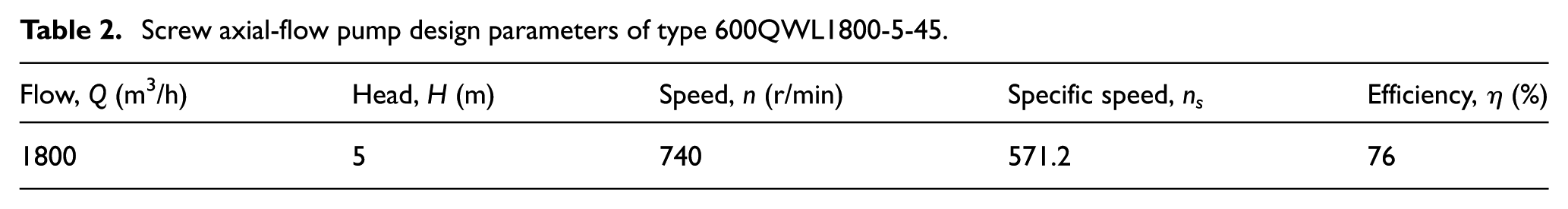
The design parameters of the screw axial-flow pump are shown in Table 2.
Screw axial-flow pump design parameters of type 600QWL1800-5-45.
The model was designed using Pro/E software. In order to make the model convergent and the result more stable, the suction and outlet domain were appropriately extended.
The whole model, in which the number of impeller blades was one and the number of guide vanes was three, composed of suction domain, impeller domain, guide vane domain, and outlet domain. The computational domain of the screw axial-flow pump is shown in Figure 3.
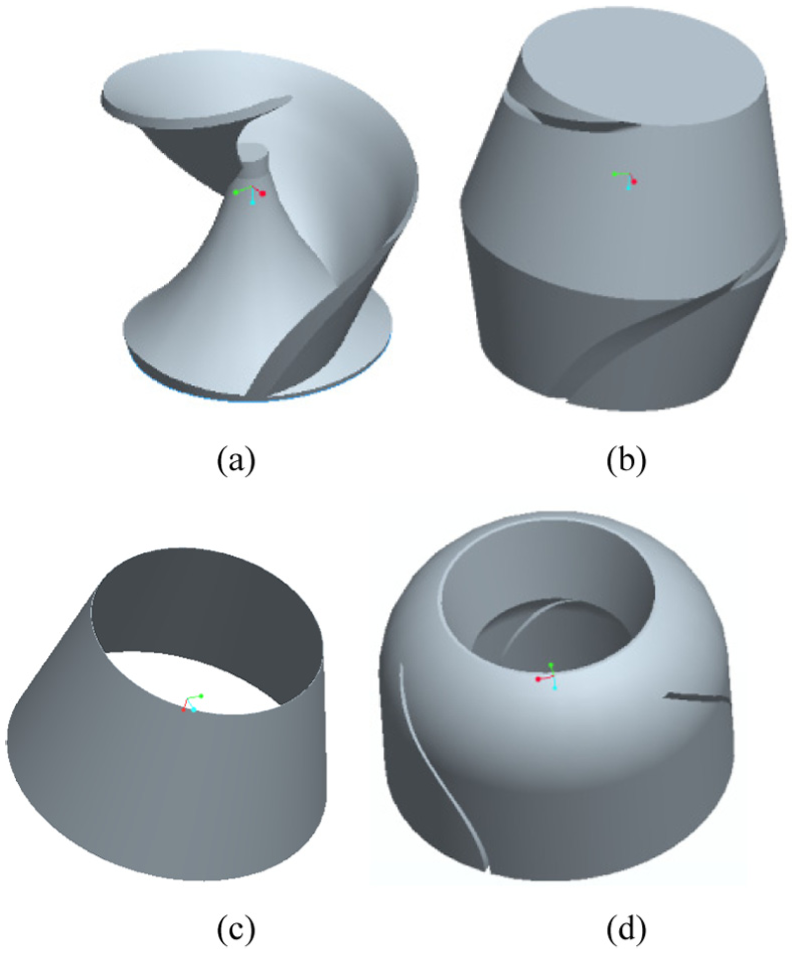
Hydraulic components: (a) impeller model, (b) impeller domain, (c) tip clearance domain, and (d) guide vane domain.
Tip clearance (RTC), shown in Figure 4, is one of the key parameters affecting the performance of the screw axial-flow pump; it is the radial distance between the inner wall of the suction and the impeller. This clearance distance is adjusted by connecting the bolts between the suction and the guide vane.

Schematic diagram of the tip clearance position.
Parameter definition


where
Grid generation and analysis
The ICEM-CFD software was used to divide the pump into hexahedral structured grids. In order to refine the grids, the grid independence of the model was studied. When the number of grids was more than 1.5 million, the variation range of the design point of the pump was less than 1%, considering the calculation time and the model size.
The grid of scheme 2 was finally adopted. The specific grid parameters are shown in Table 3. The fluid domain grid is shown in Figure 5.
Analysis of grid independence.


Grid schematic diagram of fluid domain: (a) impeller structure grid, (b) impeller domain grid, (c) tip clearance domain grid, (d) guide vane domain grid, and (e) assembly grid.
Mathematical model
Governing equations
The governing mixture equations for mass and momentum are


The liquid–vapor mass transfer due to the cavitation was modeled by a vapor volume fraction transport equation

Amidst ui is the velocity vector, ρm is the mixture density, ρv is the vapor density, ρl is the liquid density, αv is the vapor volume fraction, µ and µt are the mixture dynamic viscosity and the turbulent viscosity, respectively, and Re and Rc are the mass transfer source terms related to the evaporation and the condensation of the liquid and vapor phases in the cavitation.
The mixture density ρm and the mixture dynamic viscosity µ are defined as


Cavitation model
The cavitation model, developed by Zwart et al., solved the following transport equation for αv in equation (5). Source terms Re and Rc were derived from the bubble dynamics equation of the generalized Rayleigh–Plesset equation that accounts for mass transfer between the vapor and liquid phases in cavitation.
They have the following forms

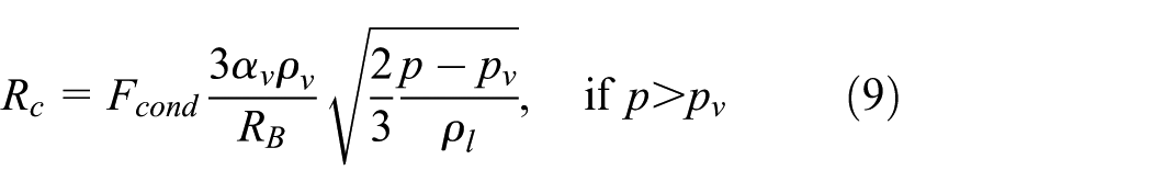
The model involves four parameters, and default values are used here. They are as follows: the bubble radius RB = 10−6 m, the nucleation site volume fraction rnuc = 5 × 10⁻⁴, and the vaporization and condensation coefficients Fvap = 50 and Fcond = 0.01, respectively.
Boundary conditions
ANSYS CFX was used for the numerical calculation. The software used the finite volume method (CV-FEM) 19 coupled with the finite element method. The standard k − ε model was used to numerically simulate the screw axial-flow pump. To ensure the accuracy and save the calculation time, the difference scheme used a specified blend factor of 0.75, setting the convergence accuracy to 10−5.20,21 The frozen rotor interface was used for the coupling between impeller and guide vane. The reference pressure was set to 0 atm, and the pressure in the flow field was the absolute pressure.
In order to make the calculated flow field closer to the real situation, the pressure inlet and the mass flow outlet were used to set the boundary conditions for the calculation. According to the actual submerged depth of the screw axial-flow pump, the inlet pressure was set to 1 atm and the outlet mass flow rate was set at 500 kg/s. When cavitation was calculated, the result of non-cavitation was used as the initial value of cavitation calculation. Water and water vapor at 25°C were selected as the working medium. The density of water was 997 kg/m3, and that of water vapor was 0.02308 kg/m3. The saturated vapor pressure was 3169 Pa. The volume fractions of water and water vapor at the inlet were set to 1 and 0, respectively.
Simulation accuracy validation
Figure 6 shows the comparison of test and simulated values of the external characteristics of the screw axial-flow pump. It can be seen that there is a certain deviation between the simulation value and the test value, and the simulation performance is higher than that of the prototype test. Whereas, the overall trend of the curve is consistent, with the maximum deviation of the head less than 4%, and the maximum deviation of efficiency below 6.2%.

Comparison of test and simulated values of the external characteristics of the test pump.
Since the numerical simulation calculation only predicted the hydraulic efficiency of the computational domain, only the hydraulic loss in the computational domain was taken into consideration. The actual losses of screw axial-flow pump, besides the hydraulic losses, include leakage loss, mechanical loss, and others. So, the predicted performance is higher than the actual performance of the pump. In summary, the CFD numerical simulation has certain accuracy and reliability, which can provide reference for the optimization design of screw axial-flow pump.
Results and analysis
Influence of tip clearance on external characteristics of screw axial-flow pump
Figure 7 shows the head, efficiency, and shaft power simulations for a screw axial-flow pump with different tip clearances. As shown in Figure 7, with the increase in the RTC, the head, efficiency, and shaft power of the pump at each working point decreased under the same flow rate. This is because as RTC increased, the vorticity and the reflow area of the tip clearance area increased, loss of contraction and diffusion expanded, and the Q–H curve, Q–η curve, and Q–P curve went down. However, the reduction in external characteristics was not proportional to the increase in RTC, and the performance of small flow and large flow conditions diverged.

External characteristics curve for different RTC.
For every 1-mm increase in RTC, the average efficiency of the whole operating conditions decreased from 1.94% to 2.36%, showing an accelerated downward trend. In the small flow conditions, the average efficiency decreased from 2.12% to 2.4% for every 1-mm increase in the RTC, which is greater than the average efficiency of the whole operating conditions. Namely, with the increase in the RTC, the efficiency of the small flow condition decreases. In the large flow conditions, the average efficiency decreased from 1.67% to 2.18% for every 1-mm increase in the clearance, less than the average efficiency of the whole operating condition. It can be seen that the RTC is not sensitive to the efficiency of large flow conditions, and the drop of head and efficiency in large flow conditions is smaller than that in small flow conditions. This is because the inlet angle of the blade is a positive angle, which can increase the area of the over-flow of the blade and reduce the blade squeeze, so the pump backflow and swirl range decreased, and the internal flow pattern improved under large flow conditions.
Influence of tip clearance on internal flow field in screw axial-flow pump
Figure 8 shows the vorticity distribution of the impeller shaft surface under different blade tip clearances at the design conditions. It can be seen from Figure 8 that when the RTC = 1 mm, the vorticity mainly distributed near the hub of the blade inlet.

Vorticity distribution of impeller shaft (Q = Qopt): (a) RTC = 1 mm, (b) RTC = 2 mm, and (c) RTC = 3 mm.
This is because in the screw impeller inlet part, the blade screw angle was small, so the role of the blade to promote the liquid weakened. And the impeller did not meet the flow condition here so that the partial liquid could not get enough energy, thereby forming a dead zone and a low-velocity circulation area within a large radius centered on the hub. When RTC = 2 mm, the vorticity began to appear near the tip of the blade inlet. As the RTC continued to increase, the vorticity at the tip became stronger and the swirl area expanded. This is because with the increase in the tip clearance, the vortex and backflow area of the tip clearance area expanded, and the vortex intensity strengthened.
Figure 9 shows the vorticity distribution at different streamlines on the suction-side of the blade under different blade tip clearances at the design conditions. Figure 9 shows that the vorticity was mainly distributed near the hub and tip of the impeller inlet, corresponding to Figure 8.
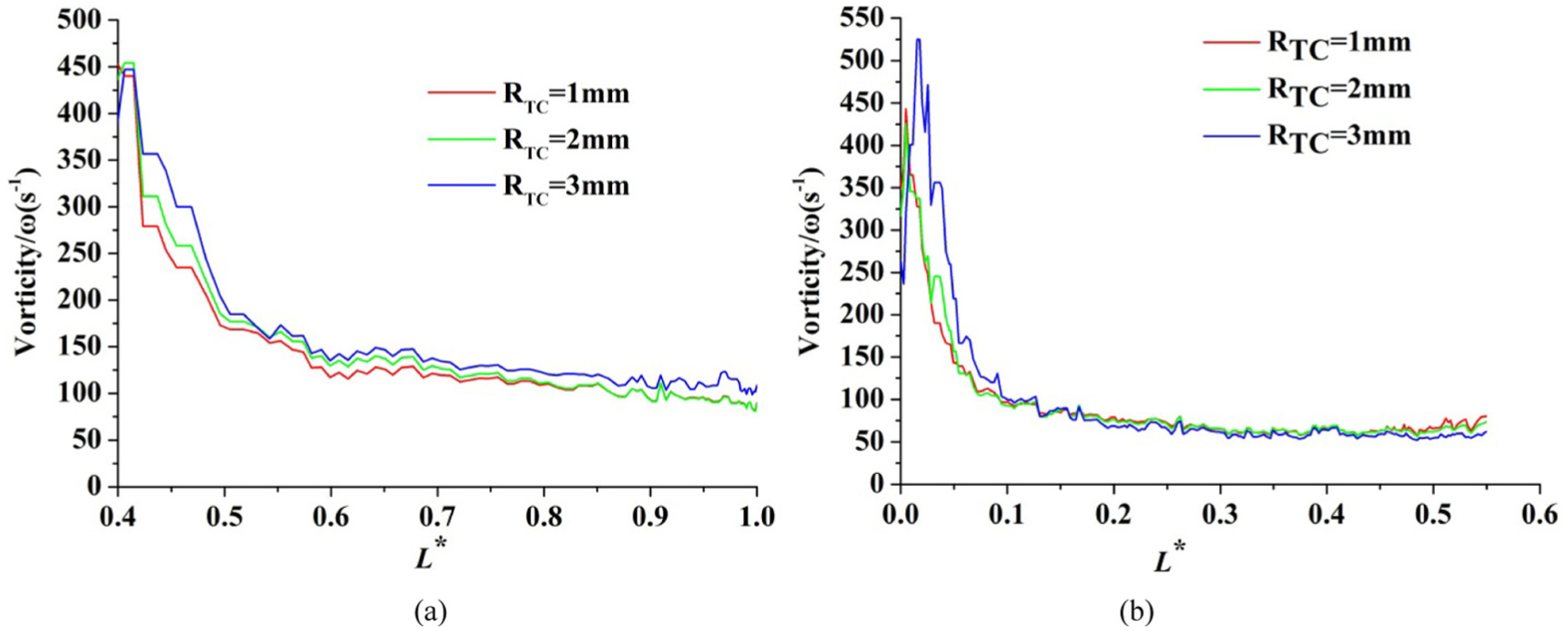
Distribution of vorticity at different streamlines on blade suction-side (Q = Qopt): (a) streamline on the hub of blade suction-side and (b) streamline on the rim of blade suction-side.
Let the inner vorticity of the impeller be increased with RTC. When the RTC was 2 mm, the vorticity on the tip of blade suction-side increased little. As the RTC went up, the vorticity on the tip of blade suction-side increased rapidly in
Analysis of cavitation performance of screw axial-flow pump
Effect of tip clearance on cavitation performance of pump
Figure 10 shows the pump H–NPSH curves under different tip clearances (Q = Qopt).

Simulation of NPSH curve under different RTC (Q = Qopt).
Figure 10 shows that with the increase in the tip clearance, the NPSH curve decreased and NPSHc (critical NPSH) gradually increased, together with earlier and earlier cavitation of the pump, the performance of which became worse.
Effect of cavitation number on vapor volume fraction inside impeller
Figure 11 shows the distribution of the isosurface of the inner cavity of the impeller under the different cavitation numbers for the pump model (RTC = 1 mm). From the figure, we can see that in the incipient cavitation stage (

Distribution of the isosurface of the inner cavity of the impeller (RTC = 1 mm, isosurface = 0.6, Q = Qopt): (a) incipient (σ = 0.222), (b) critical (σ = 0.067), and (c) fractured (σ = 0.054).
Figure 12 shows the curve of the vapor volume fraction at different streamlines on the suction-side of the impeller at RTC = 1 mm (Q = Qopt). From the figure, we can see that in the incipient cavitation stage (

Vapor volume fraction at different streamlines on impeller suction-side (RTC = 1 mm, Q = Qopt): (a) impeller hub streamline, (b) middle streamline, and (c) impeller rim streamline.
In the critical cavitation stage (
When the cavitation number reduced to the fracture cavitation state (
Experimental research and serialization of screw axial-flow pump
Test device
Whether the pump test device is suitable or not has a direct impact on the measured pump performance. It should have the following characteristics: isostatic pressure distribution, axisymmetric velocity distribution, and no device-induced vortex. Pump test device can be divided into closed-type and open-type, according to the circulating pipeline, and the paper applied for open-type test device to test. Open test device has many advantages: simple structure, stability, good heat dissipation, and easy to manipulate.
Its deficit is the need to adjust the opening angle of the inlet valve, during the cavitation test. This will lead to the pump inlet flow state instability, which affects the accuracy of cavitation performance measurement. The capacity of the open test tank can be determined as follows: the capacity is equal to the volume of liquid pumped 5–7 min plus 20%–30% of the margin, the depth of the tank is 2–5 m, and the length of the tank is 10–20 times of the diameter of the largest pipeline. The schematic diagram of the test device is shown in Figure 13. Test pump is shown in Figure 14.

Test device for screw axial-flow pump: 1. test pump, 2. wire rope, 3. wellbore, 4. power cable, 5. signal cable, 6. diffusion pipe, 7. pressure gauge, 8. electromagnetic flowmeter, 9. regulating valve, 10. elbow, 11. water tank, 12. support frame, and 13. foundation.

Test pump.
Serialization of the pump
At present, the screw axial-flow pump has achieved good results and is well received by users as the sludge return pump. In view of user needs and product development needs, this article carried out a series of research. Now, there are four types of screw axial-flow pump, 300QWL900-5-22, 600QWL1800-5-45, 800QWL3600-5-80, and 900QWL5400-5-120. Its series of products also produced volute pressure chamber, in addition to guide vane pressure chamber. Various types of screw axial-flow pumps are shown in Figure 15.

Different types of screw axial-flow pump products.
Conclusion
With the increase in the RTC, head, efficiency, and shaft power of the pump at each working point decreased under the same flow rate. The RTC was not sensitive to the efficiency of large flow condition, and the decrease in head and efficiency of the pump in large flow conditions was smaller than that for small flow conditions.
With the increase in RTC, the vorticity distribution in the impeller gradually spreads from the hub to the tip of the blade inlet.
With the increase in the tip clearance, the NPSH curve decreased and NPSHc (Critical NPSH) gradually increased, together with earlier and earlier cavitation of the pump, the performance of which became worse.
In the incipient cavitation stage, the cavitation was mainly located at the inlet of the blade suction-side near the hub, and with the development of cavitation, the tip cavitation began to emerge. When the cavitation number reached the fracture cavitation state (
The simulation results were in good agreement with the experimental values. It can be seen that the CFD numerical simulations have certain accuracy and reliability, which can be used to optimize the design of screw axial-flow pump.
Footnotes
Academic Editor: Jose Ramon Serrano
Declaration of conflicting interests
The author(s) declared no potential conflicts of interest with respect to the research, authorship, and/or publication of this article.
Funding
The author(s) disclosed receipt of the following financial support for the research, authorship, and/or publication of this article: This work was supported by the National Natural Science Foundation of China (grant no. 51409197), the Hubei Provincial Natural Science Foundation of China (grant no. 2015CFB253), and the Water Conservancy Key Research Projects of Hubei Province (nos HBSLKJHT201307 and HBSLKJHT201701).