
Abstract
As core components of wind power equipment, wind turbine gearboxes usually work in hostile conditions, which accounts for the increasing failure rate year by year. Therefore, the condition monitoring and fault diagnosis play a vital role in the safe operation of wind power gearboxes. Compared with ordinary gear train, wind power gearboxes have more complex transfer systems. Moreover, the vibration combination generated by multi-gears meshing and time-variant transfer paths of vibration signals increases the difficulty of wind turbine gearboxes fault diagnosis. To accurately detect the faults and analyze the fault signal transfer mechanism of planetary gearboxes, this article proposes a novel method based on power flow finite element to study transfer paths. For localized spalling of planetary gears, this article analyzes six transfer paths’ contributions of the fault signal and carries on the finite element analysis to determine the dominant transfer path. By contrast, the proposed method overcomes the problems of mutual coherence and time variance requested for traditional transfer path analysis methods and reveals the changes of energy and attenuation law. The detection of dominant transfer path will greatly promote the reveal of failure mechanism and fault feature extraction for wind turbine gearboxes, which has significant academic and engineering value.
Keywords
Introduction
Wind turbine gearboxes are core components of the wind power equipment. In terms of hostile working conditions, they are the easiest ones to break down. Current wind turbine gearboxes mostly contain primary planetary gears, and they have more complex structures than gearboxes with fixed shaft axles. In wind turbine gearboxes, vibration combination caused by multi-gears meshing and time-variant transfer paths of fault vibration signals increase the difficulty of condition monitoring and fault diagnosis. The study on transfer paths will make contributions to fault feature extraction and the reveal of failure mechanism for wind turbine gearboxes, which will be of great significance to theory and practical value in engineering.
In recent years, many scholars pay much attention to the research on transfer paths in the field of fault diagnosis and have made great progress. Sitter et al. 1 described a procedure to recognize the transfer paths, which overcame the drawbacks of time-consuming disassembling and wrong boundary conditions in classical experimental transfer path analysis. The vibration signal transfer paths of gearboxes and noise signal transfer paths were identified based on the improved operational transfer path analysis.2,3 Niu et al. 4 compared the characteristics of acceleration and torsional vibration signals obtained from different transfer paths and applied the bispectrum analysis to extract the fault features. Liang et al. 5 took effects of multi-vibration sources and transfer paths into consideration to establish the vibration signal model of planetary gear tooth crack. And it was applied to the fault diagnosis of sun gears. Via comparing the transfer characteristics of three paths, the dominant transfer path of gearbox fault signal was determined successfully. 6 A phenomenological model of vibration signal of epicyclic gearboxes was developed using window functions with different amplitudes, in order to describe the energy loss of two time-variant transfer paths from sun-planet/ring-planetary gear meshing point to the sensor. 7 Based on the best measured points, Xu et al. 8 found out the characteristics of transfer functions with small changes in system stiffness and identified the fault of the gear crack. Huang et al. 9 established the finite element model of the planetary gearbox sets and obtained the mathematical relationship between the meshing vibration signal and transfer path through curve fitting. Lei et al. 10 analyzed the transfer paths of meshing point vibration signal in planetary gears and established the simulation model of vibration signal, which contained the phase difference between each meshing composition.
The methods above are almost based on frequency response function; at the same time, the transfer path analysis method on the basis of energy has attracted increasing attention. Kim et al. 11 derived out a simple formula to calculate the vibration power flow from the centrifugal turbo blower to the chassis frame in a fuel cell electric vehicle, and the formula was applied to recognize the vibration transfer path. By analyzing the mechanism and transfer paths of vibration and noise, a calculation method of vibration power flow generated by gear meshing in gearboxes was studied. 12 Furthermore, the dynamical model of “the plate-rolling bearing—gear shaft—rolling bearing—plate” was established. Meanwhile, the modal solution of the vibration power flow transmitted to the plate through rolling bearing was deduced. In case considering meshing power loss or not, Hu et al. 13 used the theory of virtual work to analyze the power flow of compound planetary transfer with cone gear. Yang et al. 14 reported a new method to calculate the power flow of planetary gears based on hypergraph and matrix operation. And the equations about power loss on each coupling node are presented. Xu and Ma 15 first proposed the recognition law of dominant path, and a numerical solution on nodes was applied to evaluate the transfer path of the structure.
To summarize, the studies about vibration signal transfer paths mainly concentrate on the noise detection and vibration elimination for automobiles and other large devices. As requested in traditional methods, all transfer paths need to be completely independent, and it is easy to install sensors inside the equipment. But for wind turbine gearboxes, planetary gears can easily cause the vibration superposition, and there are multiple time-variant and time-invariant transfer paths existing simultaneously. And the internal structures of gearboxes are not suitable for installing sensors. All these problems bring great challenges to the transfer path analysis of fault vibration signal for gearboxes. However, the methods based on energy can turn complex vector operations to relatively simple scalar addition and subtraction, which provide an absolute measurement of vibration energy transfer and reveal the changes of energy transfer and the law of attenuation. However, the current research is still in the initial stage, and the dominant transfer path is simply identified just by comparing the power flow in a particular interface, which lacks the research on vibration energy contribution to the target point. Therefore, the existing transfer path analysis methods are invalid under this condition.
To overcome the shortcomings of the current methods, this article presents a novel transfer path analysis method of fault signal for gearboxes, based on power flow finite element. This method takes both time-variant and time-invariant paths into consideration and uses power flow to evaluate the energy contributions of paths to the target point, so that the dominant transfer path can be accurately determined. First, the theoretical contribution calculation formula of the transfer path is deduced in this article. Then, according to the special structures of gearboxes, it analyzes every transfer path of fault signal, including time-variant and time-invariant paths. Finally, it calculates the total contribution of each path through finite element method and sorts them to determine the dominant transfer path of fault vibration signal.
This article is organized as follows: The basic principle of transfer path analysis is introduced in section “Theory of transfer path analysis.” In consideration of the shortcomings of traditional evaluation index, based on power flow, the calculation method of transfer path contribution is presented in section “Contribution calculation method based on power flow.” According to the time-variant and time-invariant transfer paths of fault vibration signal in gearboxes, the contribution calculation is proposed in section “Analysis of transfer paths.” Via finite element simulation analysis of transfer paths, the dominant transfer path is determined in section “Finite element simulation analysis.”
Theory of transfer path analysis
Transfer path analysis is a powerful engineering method when analyzing the vibration and noise of equipment and products, especially for the complex vibration mechanism that is difficult to model and measure. The present applications mainly concentrate on automotive engineering, shipping engineering, aircrafts, construction engineering, and large equipment.
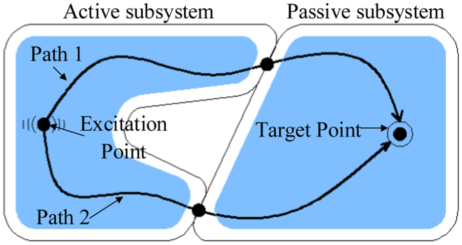
For a vibration signal transfer system, three important parts are, respectively, the excitation point, transfer paths, and the target point. Excitation and target points can be single or multiple. Multiple target points can be seen as multiple transfer path systems. When analyzing the transfer paths, the transfer system is usually decomposed into two subsystems, including active and passive subsystems. Active and passive subsystems are where excitation point and target point exist, respectively. The joint of active and passive subsystems is the coupling point, as shown in Figure 1. Transfer path is the physical media, which refers to specific media that the vibration transmitted from the excitation point to the target point passes through. When vibration signal is transmitted through different transfer paths, on account of the difference on transfer media and transfer distances, it will cause various degrees of attenuation. Transfer media mainly consist of structures and air. This article aims at the study on transfer paths of wind turbine gearboxes fault vibration signal, so only structures need to be considered as the transfer medium.
The single-excitation system.
The vibration generated at excitation point is transmitted in the form of force and motion to the target point along the transfer path. And the total response of the target point is the energy sum that external load passes along different paths to target.
The basic principle of transfer path analysis based on energy method is as follows

where
The instantaneous power of one point in a vibration transfer path system is defined as the vector product of dynamic load and response speed at the point

where
If the load is simple harmonic, the velocity response will also change in accordance with the law of harmonic. Thus, the average power in a period can be defined as follows

where

where “—” represents the conjugate vector. If
Contribution calculation method based on power flow
The purpose of the transfer path analysis is to quantify the contribution of each transfer path to the target point and sort them according to the importance. It helps to provide the basis for further study on noise and vibration reduction. However, it is difficult to clearly clarify the contributions of transfer paths for a complex vibration transfer path system. The indexes that are used to evaluate the contribution mainly include the vibration responses (such as force, velocity, and acceleration) and power flow. Due to the vector feature of force, velocity, and acceleration, it is hard to compare the indexes with others. What is more, a single index can hardly evaluate the contributions of transfer paths comprehensively. But power flow takes both the functions of force and velocity and the essence of vibration energy into consideration. It gives an absolute measurement of vibration energy so that it has been recognized and utilized widely. Therefore, this article uses power flow as the evaluation index and analyzes the transfer path contributions of fault vibration signals for wind turbine gearboxes to determine dominant transfer path.
According to equation (1), for the vibration system with n transfer paths, the power flow at the target point is defined as

where

For a single-excitation system in Figure 2, the vibration energy is transferred from the excitation point to the coupling point and then is transferred to the target point jointly. For transfer path i, the energy conservation factor in active subsystem is


Energy transfer of a single-excitation system.
With the power flow of each path and energy conservation factors of active and passive subsystems, it can calculate the contribution percentage of any path according to equations (6) and (7). However, it is difficult to obtain the power flow of each path directly because the power flow that passes through each path is not fixed. Accessing to the power flow at the coupling point can be a way to calculate the contribution percentage based on the passive-subsystem energy transfer diagram shown in Figure 3. Considering the power flow at the coupling point as


Energy transfer of the passive subsystem.
Substituting equations (7) and (8) into equation (6), the contribution percentage of transfer path i is

Equation (9) indicates that the power flow at passive-subsystem coupling point and the energy conservation factors under working conditions are variable to be obtained. According to the concept of transfer rate, the energy conservation factor as energy transfer rate is the intrinsic characteristic of a mechanical structure and can be obtained by experiments or simulations. To obtain the factors, the actual excitation source needs to be removed. Then, it applies excitation to passive-subsystem coupling point in turn and measures the power flow of the target point at the same time. The ratio of the target and coupling point power flow is the energy conservation factor. For a system consisting of n paths, the power flow at passive-subsystem coupling point can be obtained in the following steps:
Select m instruction points near the target point in passive subsystem and one monitoring point near each coupling point. Under working condition, the power flow is obtained at each instruction point by experiments or simulations and combined into a m-dimensional column vector
Remove the actual excitation source and apply excitation to passive-subsystem coupling points in turn and then obtain the power flow at each instruction and monitoring point through sensors or simulations. When applying excitation to ith path coupling point, power flow of ith path monitoring point is
Record


Denote the inverse matrix of

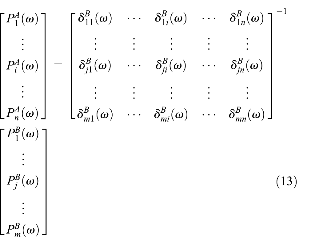
Hence, the contribution percentage of transfer path i is

From the above analysis, the contributions of transfer paths mainly depend on the power flow under actual working conditions, as well as the power flow at the instruction points and the energy conservation factors. To obtain the power flow and energy conservation factors, the analysis of fault vibration signal transfer path is of great importance and is also the premise of calculating contribution of each transfer path.
Analysis of transfer paths
Transfer path
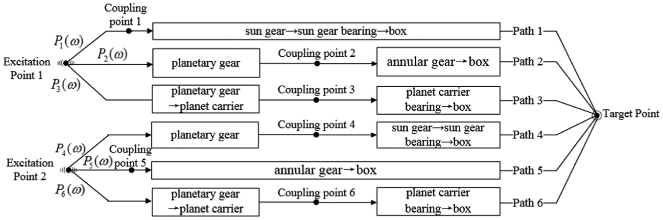
Transfer paths of planetary gear fault vibration signal in gearboxes are shown in Figure 4. There are six transfer paths from fault source to the sensor because of the planetary gear meshing with annular gear and sun gear. According to different meshing components, the paths can be separated into two classes. One is the transfer paths that are formed when planetary gear fault point meshing with the sun gear, including paths 1, 2, and 3. The other one is on account of the planetary gear fault point meshing with annular gear, including paths 4, 5, and 6. Among them, paths 1, 3, 4, and 6 are time invariant, and each one has a fixed length. On the contrary, paths 2 and 5 are both time variant because the distance between the fault point and the sensor changes periodically when the planet carrier rotates, as shown in Figure 5. When the fault point gradually approaches the sensor, the amplitude of measured signal increases gradually. On the contrary, the amplitude decreases when gradually moving away from the sensor. The components that each path passes through are listed as follows:
Path 1: sun gear—sun gear bearing—box—sensor;
Path 2: planetary gear—annular gear—box—sensor;
Path 3: planetary gear—planet carrier—planet carrier bearing—box—sensor;
Path 4: planetary gear—sun gear—sun gear bearing—box—sensor;
Path 5: annular gear—box—sensor;
Path 6: planetary gear—planet carrier—planet carrier bearing—box—sensor.

Transfer path of planetary gear fault vibration signal.

Time-variant paths of planetary gear fault vibration signal.
Contribution theoretical calculation
Although the vibration signal of planetary gear localized spalling has six transfer paths, these paths are generated when fault gear meshes with sun gear and annular gear separately. And each fault meshing point corresponds to three transfer paths. Vibration generated by these two fault meshing points has clear orders in the time domain, which is different from the system consisting of two excitation points. Therefore, it is still a single-excitation system. To establish system energy transfer graph, the coupling points are chosen as follows:
The coupling point of path 1 is at the sun gear;
The coupling point of path 2 is the meshing point of the planet and annular gear;
The coupling point of path 3 is between planet carrier and its bearing;
The coupling point of path 4 is the meshing point of the planet and sun gear;
The coupling point of path 5 is at the annular gear;
The coupling point of path 6 is between planet carrier and its bearing.
When considering the meshing point of fault gear and sun gear as excitation point 1 and the meshing point of fault gear and annular gear as excitation point 2, the system and passive-subsystem energy transfer graphs are shown in Figures 6 and 7, respectively.
Energy transfer of planetary gear fault.

Energy transfer of passive subsystem for planetary gear fault.
Obviously, paths 1 and 4, paths 2 and 5, and paths 3 and 6 have the same energy transfer path, respectively. Although paths 2 and 5 are time variant and fault meshing points are also different in working conditions, fault vibration signal is transferred to the sensor through each tooth of annular gear in both paths 2 and 5 because the annular gear is fixed. It means that the energy conservation factors of paths 2 and 5 are both the functions about the meshing tooth number of planetary gear and annular gear. Meanwhile, because energy conservation factors are intrinsic characteristics of structures, paths 1 and 4, paths 2 and 5, and paths 3 and 6 have equal energy conservation factors, respectively. Number the annular gear and take the tooth opposite to underneath of the sensor as No. 1. Due to annular gear’s symmetry about the sensor, only half of the teeth need to be numbered, as shown in Figure 8. Then, set a monitoring point near each coupling point and three instruction points near the target point. Thus, equations (15) and (16) can be deduced from equation (11)


Tooth numbering of time-variant paths.
In order to calculate more conveniently, adapt equations (15) and (16) to equation (17)

On the basis of equation (14), the contribution percentage of each transfer path can be expressed

According to time-variant and time-invariant transfer paths of localized spalling vibration signal, the proposed method deduces the concrete calculation formula of transfer path contributions, which lays the theoretical foundation for the finite element simulation analysis.
Finite element simulation analysis
Power flow finite element method
Power flow finite element method is an approach usually used to predict the vibration energy of structures and has attracted more and more attentions. First, it utilizes the finite element software to analyze the structural vibration response. Then, the power flow at the target point is obtained to evaluate structural vibration transfer characteristics, according to the basic theory. In finite element model, to obtain the power flow, it is necessary to obtain the force and velocity of the node. For the node k connected with several solid elements, the power flow passing through the node can be calculated

where

Numerical analysis
This article utilizes ANSYS as the platform of finite element analysis. Before the analysis, the finite element model and some other related information of the wind turbine gearboxes have to be provided. Moreover, considering the sole connection function, the bolts, nuts, threaded holes, and through-holes are eliminated, which would not affect the analysis accuracy. The original and simplified models are shown in Figure 9.
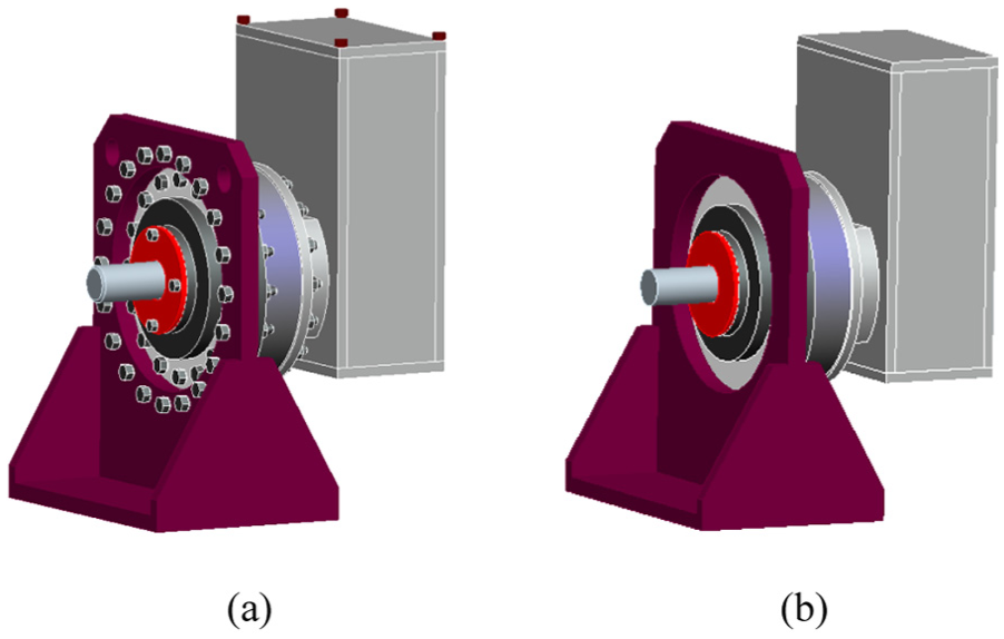
Finite element models: (a) original model and (b) simplified model.
Modal analysis
Modal analysis is a kind of linear dynamic analysis, and it is usually used to identify the inherent vibration characteristics of mechanical structures. In terms of the vibration energy transmitting internally, the sizes of mesh grids should be less than one-sixth of the vibration wavelength. 16 In the air and metal, the mechanical vibration wave spreads at the speed of 330 and 4900 m/s, respectively, and the corresponding curve wavelength is 0.067–1.63 m for the maximum analysis frequency of 2850 Hz. 17 Accordingly, the mesh sizes of rolling bearings and sun gears are set 5 mm, and the others are 10 mm since the minimum size is 11 mm. The loading condition of modal analysis in this article is nonprestressed and bottom fixed. The first eight-order natural frequencies are listed in Table 1, and the corresponding modal shapes are shown in Figure 10.
Natural frequency of order modal.


First eight-order modal shapes: (a) first order, (b) second order, (c) third order, (d) fourth order, (e) fifth order, (f) sixth order, (g) seventh order, and (h) eighth order.
Harmonic response analysis
Harmonic response analysis is used to calculate the steady-state response of linear structures under sinusoidal excitation, and the purpose is to establish the relationship between vibration response and frequency.
The range of analysis frequency is set between 0 and 2850 Hz, with the load step of 50 Hz, a total of 57 steps. The impact force caused by meshing is related to the speed, modules, and materials of gears. When the module is 5, impact force ranges from 1700 to 14,000 N approximately. In this article, the initial impact force is 2000 N at the coupling point. Based on Saint-Venant principle, the monitoring point should be set to offset a certain distance from the coupling point. The coupling, monitoring, and instruction points of each fault signal transfer path are shown in Figure 11.

Instruction, coupling, and monitoring points of transfer paths: (a) instruction points, (b) coupling and monitoring points of paths 1 and 4, (c) coupling and monitoring points of path 2 and 5, and (d) coupling and monitoring points of paths 3 and 6.
Post-process the results of harmonic response analysis, obtain the power flow of each node via multiplying the force and the derivative of speed at the node, and the power flow of instruction and monitoring points in each load step are processed with MATLAB. Then, the energy conservation factors can be calculated, as well as the tendency of transfer path contribution about frequency. Thus, the dominant transfer path of fault vibration signal can be determined.
Calculation of energy conservation factors
For the transfer paths of planetary gear fault signal, there are six time-invariant energy conservation factors, including

Time-invariant energy conservation factors: (a)
There are also three time-variant energy conservation factors, including
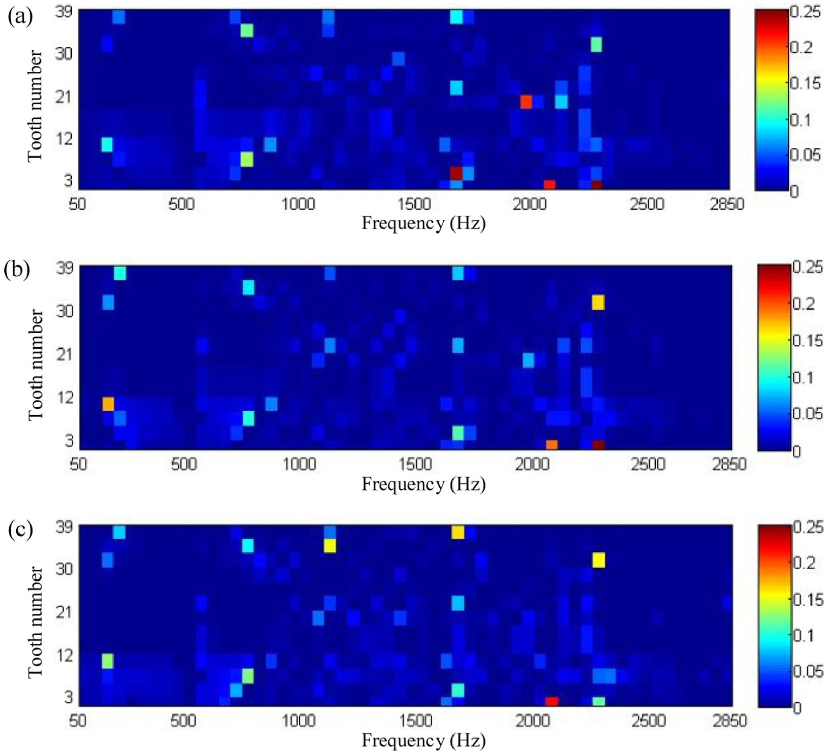
Time-variant energy conservation factors: (a)
At a fixed tooth number, summing the energy conservation factors of different frequencies, and the maximum and the minimum transfer capacity of the time-variant transfer paths can be obtained. The result is shown in Figure 14. From this figure, it is manifest that the maximum and minimum are gained when the tooth number is 9 and 27, respectively.
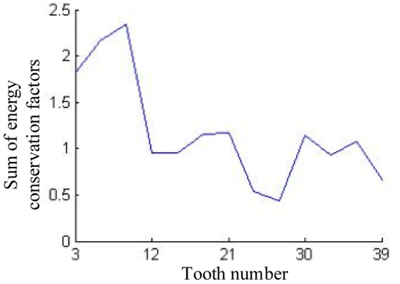
Time-variant energy conservation factors at different tooth numbers.
Analysis of contributions
According to equation (18), to calculate the contribution of each transfer path, it needs to obtain both the matrix of energy conservation factors and power flow column vector
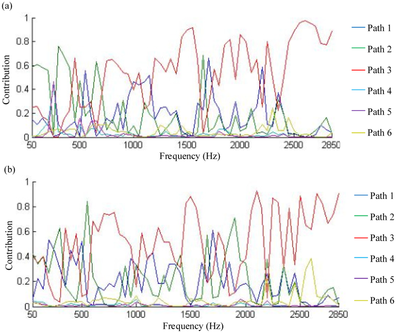
Contributions of transfer paths: (a) n = 9 and (b) n = 27.
For planetary gear fault signal, there exists three resonance bands of natural frequency, which are 2200–2850, 1450–1650, and 550–600 Hz. 17 Sum the contributions of transfer paths at each resonance band to gain the total contributions and sort them. The result is shown in Table 2. When n is equal to 9, the total contribution of each path is 2.97, 2.33, 14.08, 0.26, 0.23, and 1.14 in order. When n is equal to 27, the total contribution is 2.22, 3.38, 13.39, 0.10, 0.16, and 1.75. As analyzed, path 3 is regarded as the dominant transfer path. Meanwhile, considering two meshing points, the fault may exist at the meshing point of planetary gear and annular gear or sun gear. Thus, two dominant paths should be determined. Path 6 is also regarded as the dominant transfer path.
Rank of transfer path contributions.

In contrast to the traditional transfer path analysis method, this novel method based on power flow finite element exhibits a stronger applicability to analyzing the vibration signals of wind turbine gearboxes, where several time-variant and time-invariant paths exist simultaneously and couple with each other. Moreover, the proposed method solves the problem of numerous data that are requested for testing transfer functions and identifying loads. Through analyzing the vibration contribution of each path to the target point rather than in a specific interface, the dominant transfer path can be detected more reasonably and accurately, which provides a more suitable analysis approach for the fault vibration signals of wind turbine gearboxes.
Conclusion
To analyze the transfer paths of vibration signal in wind turbine gearboxes, a novel method based on power flow finite element method is proposed in this article. In the proposed method, the innovative design assumes that it takes both time-variant and time-invariant paths into consideration and uses power flow to evaluate the energy contributions of paths to the target point.
First, theoretical contribution calculation formula of the transfer path is deduced, based on the power flow and energy conservation factors. Second, according to the special structure of gearboxes, all transfer paths and contributions of fault vibration signal are analyzed, including time-variant and time-invariant paths. Third, the total contribution of each path is calculated through finite element method. Via summing the contributions at resonance bands of each transfer path and sorting them, the dominant transfer path of fault vibration signal is determined. By combining theoretical analysis and simulation results, some conclusions are obtained as follows:
Traditionally, mutual independence and time invariance are requested when analyzing transfer paths of fault signal. In this article, the power flow is regarded as the evaluation index. Compared with vibration response used in traditional methods, it shows better adaptability to time-variant transfer paths and also reveals the changes in energy transfer and the law of attenuation.
Since the fault vibration signal shows the same energy transfer paths in paths 1 and 4, paths 2 and 5, paths 3 and 6, respectively, their passive energy conservation factors are equal, which are all the functions about the meshing tooth number.
According to the results of finite element simulation, via calculating the total contribution of each path and sorting them, it is manifest that the total contribution of the dominant path is much larger than others. Thus, the dominant transfer path 3 of fault signal is determined effectively. Also, considering the existence of two fault points, path 6 is regarded as the other dominant transfer path.
The simulation result shows that the proposed method of transfer paths for wind turbine gearboxes based on power flow finite element method can effectively detect the dominant transfer path of fault signal. Nevertheless, there is still some work that needs further investigation, including the analysis of different faults and experiments. The experimental study will greatly advance the development of the proposed method in the academic and engineering angles.
Footnotes
Academic Editor: Dong Wang
Declaration of conflicting interests
The author(s) declared no potential conflicts of interest with respect to the research, authorship, and/or publication of this article.
Funding
The author(s) disclosed receipt of the following financial support for the research, authorship, and/or publication of this article: This study was financially supported by the National Natural Science Foundation of China (51175102) and the Fundamental Research Funds for the Central Universities (HIT.NSRIF.201638).